
Abstract
Strong steering wheel jitter during idling states of the engine can seriously deteriorate the driving comfort as well as the driving safety. The powertrain suspension system can be considered as the only essential path for the transmission of vibrations from the engine to the vehicle cab. Its vibration isolation performance directly affects the severity of vibrations on the steering wheel. In this article, aiming at solving the problem of a certain type of commercial vehicle’s steering wheel with strong idle jitter at the idle state, the intrinsic characteristics and vibration isolation performances of the powertrain suspension system were studied in detail. A multi-sensor-based measurement strategy was utilized to evaluate the idle jitter severity of the steering wheel. In order to improve the indicators of the decoupling degree, the vibration transmissibility, and the resonant frequency distributions of the engine suspension system, an optimization model of engine suspension system was established. Parameters of the optimized suspension system were obtained by multi-objective particle swarm optimization. Finally, the effectiveness and feasibility of the optimization algorithm to solve the problem of the vehicle’s steering wheel jitter at idle states were verified through a test using multiple acceleration sensors, which has practical values in the engineering field.
Keywords
Introduction
The engine emerges as the unique source of vibration in idle jitter problem of commercial vehicle. Nonstationary vibrations, generated by the engine, are transmitted via the suspension system to the frame structure or the vehicle body, and finally arrived at the bodies of driving crews through the steering driving wheel, the cab floor, and the seat.1–3 At present, in the commercial vehicles, high-power diesel engines (HPDEs) are usually adopted as the power source. However, for HPDE working at idle states, the rotation speed is relatively slow and caused severe idle jitter problems. In the cases of poor vibration isolation in the transmitting path and small differences between system frequency and excitation frequency of diesel engine, daunting idle jitter phenomenon will occur on several subsystems within the commercial vehicle. Such phenomena can appear in the forms of steering wheel jitter, rearview mirror jitter, pedal jitter, vehicle body jitter, and so on. The presence of strong jitter operations significantly endangers driving comfort and driving security.4–7 In order to prevent the resulting catastrophic accidents and enhance driving comfort, idle jitter state should be carefully monitored and effectively controlled.
In this article, we investigate the problem of steering wheel jitter in a four-cylinder diesel engine within a commercial vehicle in production. Multi-sensor measurement strategy is employed to locate. Considering the restriction of change space, we attempted to reduce the severe jitter by means of vibration isolation principles. In the procedure, optimizations on suspension system in the engine are investigated to engender a novel optimized suspension model; parametrization problems in the optimization process are solved by particle swarm optimization (PSO) algorithms. As a result, a more reasonable distribution of natural frequencies of the subsystems is obtained such that mutual excited vibrations are reduced and vibration transmitting power in irrelevant paths is decreased. With the proposed technique, the severe jitter problem on the steering wheel is alleviated at a very low price and the driving comfort is effectively enhanced.
Fundamentals of suspension vibration isolation for engine
Analysis on vibration isolation on suspension system
In the commercial vehicle, the engine suspension structure is installed between the HPDE and the vehicle body such that vibrations on irrelevant paths can be reduced or isolated.
8
The most important parameter to be considered during the design process of diesel engine suspension system is the vibration transmitting rate or the vibration isolation rate. The lower the vibration transmitting rate, the better the vibration isolation result can be obtained. Essential issues of the vibration isolation problem of diesel engine are how to properly determine the installation locations and the installation angles. To make a quantitative analysis of vibration transmitting rate between the diesel and the vehicle body, a suspension vibration transmitting

Correspondingly, the vibration isolation efficiency can be expressed as

where
Analysis on excitation frequency in the suspension structure and natural frequency in the system
According to our engineering experiences, the decaying rate in the engine suspension structure can be set

The curve of relationship between transmissibility and vibration isolation efficiency.
As indicated by the curves in Figure 1, the greater the parameter
Multi-sensor-based testing of the steering wheel jitter vibrations
Engine vibration is the source of the vibration of the steering wheel. The main transfer paths of vibration from the engine to the steering wheel are divided into two parts. On one hand, the unbalanced inertial vibration produced by the engine is transmitted from the engine to the corresponding engine frame, which then passes through the steering mechanism, steering column, and eventually reaches the steering wheel. On the other hand, because of the connection between the steering column and the cab dashboard, the vibration of the engine will be transferred to the cab through the suspension structure when passing through the corresponding frame of the engine, and finally, it will be transferred to the steering fixed support structure to affect the steering wheel through the dashboard. The vibration transmission path is presented in Figure 2.

The chart of the vibration transmission path.
To make a quantitative analysis on the jitter vibrations of the steering wheel, in this article, we select a typical type of commercial vehicle with such problem. A LMS testing set-up was employed to make idle state measurement. The multi-sensor-based static testing strategy is shown in Figure 3. Nine three-axis acceleration sensors are mounted on the steering wheel.

The chart of the sensor deployment.
Because there are no universal quantitative criteria for jitter severity of steering wheel, we can only rely on experiences-based rule. We have solicited investigation to many experts in this field and a proper judgment rule is derived. When the acceleration of the steering wheel on the Y direction is smaller than 0.5 m/s2, the driver received a comfort experience. While for an acceleration greater than 1.5 m/s2, the driver is working at harsh conditions.
System dynamic model of suspension structure
Generally, the natural frequencies of the suspension structure of a diesel engine are low in value, much less in value in comparison with the resonance frequency of the lowest elastic mode within the power assembly. Hence, it is feasible to only consider the distributions of rigid-body vibration modes. On the other hand, due to the low values of rubber cushion of the suspension structure in the decaying rate, it is also feasible to ignore this factor in the design process. 9 Theoretically, natural vibration characteristics of the engine suspension structure can be determined using the following formula

where

Using the above dynamic model, after obtaining the total mass of the power assembly, centroid position, moment of inertia, product of inertia, and respective stiffness of tree directions of the suspension structure, it is ready to calculate the mass matrix
Decoupling analysis on suspension structure
Typically, vibrations of the 6 degrees of freedom on the diesel engine suspension system are coupled. The mutual excitation can increase the vibration severity of diesel engine as well as broadening the vibration frequency bandwidth, therefore hampering the efforts in avoiding the approaching of excitation frequency.
10
In the state-of-the-art techniques, it is possible to evaluate the decoupling degree in the aspect of energy.
11
That is, when considering the

where
According to the above expression, it is feasible to determine the energy decoupling degree of each elastic mode of the investigated system. As long as the self-energy contribution reaches the value of 100% along a specific direction, the system is said to be entirely decoupled in the specific natural frequency. In practical applications, for obtaining better vibration isolation performance, it is beneficial to increase the decoupling degree in each elastic mode. Therefore, improvement in the suspension structure performance can be derived.
Optimization modeling for suspension structure in the diesel engine system
Coordinate definition of the diesel engine system
The power assembly is always large in mass for a commercial vehicle. It is common to make separate testing of mass parameters of diesel engine, containing clutch coupling, and the transmission gear-box and finally assemble the mass matrix

Coordinate system of diesel engine.
Optimization model of suspension structure
Aiming at solving the idle jitter problem of a type of commercial vehicle in production, we comprehensively consider some major parameters in the suspension structure in the diesel engine. Such parameters include energy decoupling degree, vibration transmission efficiency in the Z direction, and natural resonance frequencies of the suspension structure. We can summarize the above mode using the following parameter optimization model

where
Optimization based on PSO algorithm
Optimization algorithm
PSO, a global search evolutionary computing technique, which carries out parallel computing based on few parameters and simple principle, preserves the characteristics of global search strategy and parallel processing of genetic algorithm, and determines the fitness of each particle according to the objective function. 12 At each iteration of the particle flight, the method updates itself by tracking two extreme values experienced by the particle as it flies, which makes it possible for searching the target according to the adaptive information of the individual and not restricted by function constraints. The particle updates its velocity and new position according to the following formula


Here, N represents the total number of particles,
The detailed steps for the entire process are outlined below:
Initial parameters: given population size N, c1, c2,
Initialization of particle populations: according to the constraint conditions, 20 particles can be randomly generated in the position x, velocity v.
The fitness of each particle is calculated. The individual extremum
According to the distance relation of each particle, the position x and velocity v of the particle are updated using formulas (7) and (8).
Update the individual extremum
Return step 4 for 100 iterations.
The selection of parameters in this article is as follows: population size is 20, particle size is 12, maximum iteration number nmax = 100, learning factor c1 = c2 = 2, and maximum particle velocity vmax = 1 × 10³. The maximum inertial weight factor
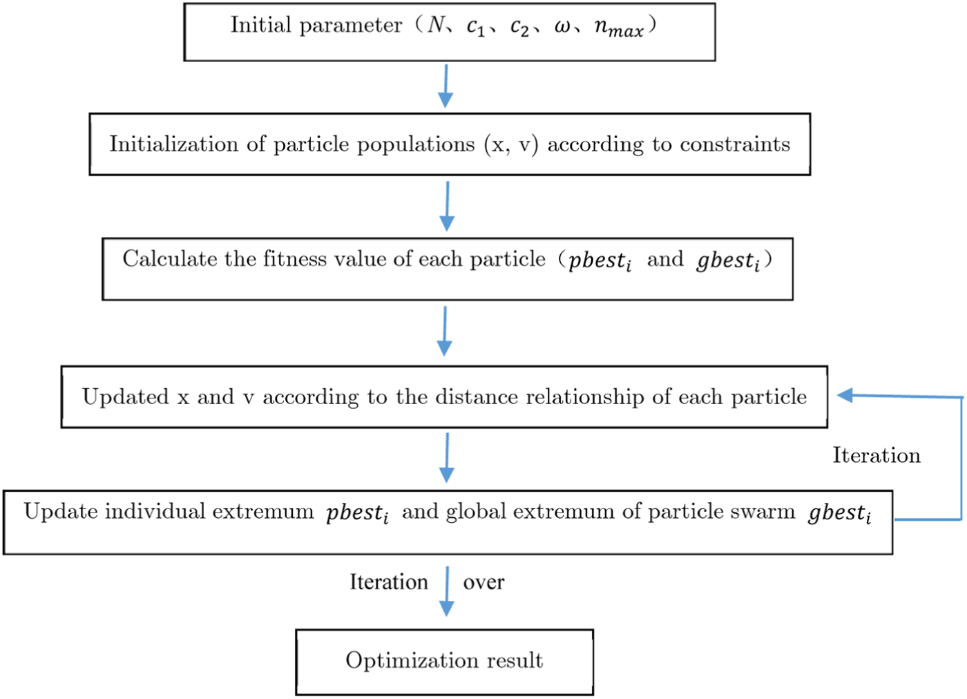
Optimization algorithm flow chart.
The design variables
The dynamic characteristics of the powertrain system are related to the quality of the engine, moment of inertia, and the geometry and dynamic parameters of the mount. However, the characteristics of the engine assembly itself cannot be changed, and the mounting position and angle are limited by the frame and other devices; additionally, the range is very narrow. Therefore, each mounting stiffness value can be taken as the design variable. For example, the range of stiffness variation range of the front mount in the three directions (X, Y, Z) is set between 100 and 500, and the rear mount stiffness variation range is between 100 and 700 and so on.
Restriction condition
In this article, constraints can be considered and set in four ways:
Predetermined frequency constraint. According to the theory of vibration isolation,
13
the fundamentals of vibration isolation theory demonstrate that on condition that the difference of natural frequencies between two structures is greater than the bigger frequency value multiplied by
Spindle stiffness constraint of mounting element. If the stiffness of the mounting element is too small, the mounting will be too soft, which will not only lead to the increase in the displacement of the powertrain but also affect the life of the mount and may cause motion interference. The stiffness of the mount will decrease the displacement of the power assembly, but the dynamic reaction force will increase, thus the vibration transfer rate will increase. At the same time, for the rubber mounting element, the compression shear stiffness ratio should be between 3 and 8 owing to the rubber material’s own characteristics.
Vibration isolation rate constraint. The excitation force of the engine mainly exists in the vertical direction and the direction of rotation around the crankshaft. The main purpose is to control the decoupling ratio of Z direction, and the rotation around X axis is greater than 80% in order to improve the isolation rate of these two directions.
Parameter constraint. Simultaneously, we should also take the parameters
Engineering applications with multi-sensor-based verification
Original parameters
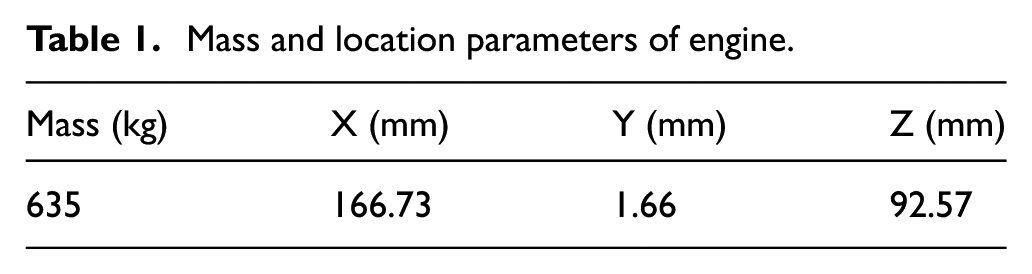
With the testing system based on the principle of tri-linear pendulum, the parameters of the total mass of the power assembly, centroid position, moment of inertia, product of inertia, and respective stiffness of tree directions of the suspension structure can be obtained.
We assemble the coefficients into a whole mass matrix, which is shown in Tables 1 and 2.
Mass and location parameters of engine.
Inertia moment parameters of engine.

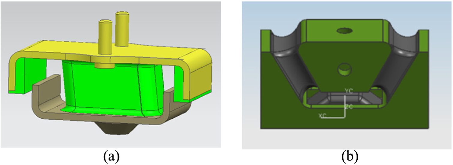
In this commercial vehicle, the front suspension system is deployed in the form of V-shape, and the rear suspension system is horizontally deployed. Because this type of commercial vehicle had been in production, changes in diesel engine type, installation locations of each suspension system, and the related installation angles are strictly prohibited (Table 3). So in this improvement, we do not attempt to make optimizations on the above parameters. The predetermined parameters are listed in Table 4. And the original front and rear suspension structure is shown in Figure 6.
Location parameters of engine mounts.

Stiffness parameters of original mounts.


Original front and rear suspension structure: (a) original front suspension mount structure and (b) original rear suspension mount structure.
According to the arguments shown in the previous sections, the natural frequencies and the resonance energy coupling distributions belonging to the first six elastic modes are shown in Table 5.
Natural frequencies energy distribution of vibration coupling in original system.
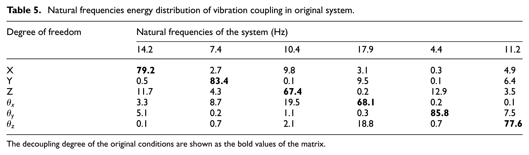
The decoupling degree of the original conditions are shown as the bold values of the matrix.
In Table 5, it is shown that the natural frequencies of the first five elastic modes are lower compared with the diesel engine firing frequency by a factor greater than
On the other hand, in the viewpoint of energy decoupling degree, the vibrations along the Y direction and the rotation Y axis are relatively good. Except for these 2 degrees of freedom, the decoupling degree of other direction is smaller than 80%. The vibration decoupling degrees on the Z direction and the rotation X axis, which are the most important dimension to be considered in the optimization, are both smaller than 70%. Based on the above data, there are severe coupling phenomena between the vibrations on the different axis, and it causes severe idle jitter vibration on the steering wheel. Proper means should be taken to solve this problem.
Analysis on the optimization results
In this article, we attempt to improve the optimization process using PSO with multi-objective fusion ability. 14 In the optimization process, the objective function is set as the minimization of suspension stiffness indicated by equation (6). As a result, the optimized stiffness coefficients of the engine suspension structure are shown in Table 6.
Optimized stiffness parameters of mounts.

As can be seen from Table 6, the optimized suspension stiffness is reduced, and the structure of mount is shown in Figure 7. Taking the optimized suspension structure matrix for establishing new system dynamic model, the updated system natural frequencies and energy decoupling rate can be obtained, as shown in Table 7.
Optimized front and rear suspension structure diagram: (a) optimized front suspension mount structure and (b) optimized rear suspension mount structure.
Natural frequencies energy distribution of vibration coupling in optimized system.

The decoupling degree of the optimized conditions are shown as the bold values of the matrix.
From Table 7, the improved natural frequencies are ranged in the interval between 4.2 and 12.9 Hz, considerably far away from the diesel engine firing frequency multiplied by a factor of
Experimental verifications
Based on the optimization scheme, we test the assembly of diesel engine suspension cushion and make whole vehicle test. Thus, we obtain the resulting curve of each hanger of each cylinder body, the suspension hanger, the driver seat lead rail, the steering wheel, and the rearview mirror. In each testing, accelerations on three orthogonal directions are collected. Vibration isolation efficiency is improved compared with the original vehicle type. For simplicity, we only demonstrate the trend of the Z direction vibration rate for left and right suspension and vibration of the steering wheel, which are strongly related to the idle jitter vibrations of the steering wheel. The comparison isolation rate curves are shown in Figures 8–11.

Comparison curves of left front mount Z direction isolation rate.

Comparison curves of right front mount Z direction isolation rate.

Comparison curves of left rear mount Z direction isolation rate.

Comparison curves of right rear mount Z direction isolation rate.
From Figures 8–11, the improvements in the isolation rates in Figures 8 and 9 are not significant, while the improvements in Figures 10 and 11 are much more pronounced. The reason is the front suspension vibration isolation rate has reached target value; therefore, the improvement of the vibration isolation rate is limited. But the initial isolation rate of rear mount is poor. After the optimization, the stiffness changes in the three directions are great. With the decrease in stiffness value, the damping effect of the rear mount is greatly improved, and the isolation rate of the rear mount is increased obviously. From the testing results from the above figures, the vibration isolation efficiencies during idle states are ranged in the interval between 82% and 86% while indicators of the original vehicle type are ranged in the interval between 73% and 81%.
By comparing vibration of idle mount before and after optimization, it can be seen from Figure 12 that the whole vibration of the improved mount is lower than that of the original state. Especially, the vibration of the rear mount is reduced from the original 1 g to about 0.5 g. After the suspension optimization and the reduction of the rear suspension stiffness, the vibration relief effect is well, and the vibration amplitude of the vibration source of the steering wheel is greatly reduced, which improves the isolation rate of the rear suspension mount.

Vibration change of mount before and after optimization.
The comparison curves of the steering wheel vibration at 3 o’clock direction before and after optimization are presented in Figures 13–15.

Comparison curves of steering wheel X direction vibration.

Comparison curves of steering wheel Y direction vibration.

Comparison curves of steering wheel Z direction vibration.
Based on the mount optimization method, this article solves the jitter problem of the steering wheel of commercial vehicles when the idling speed reaches 700 r/min. Just as shown in Figures 13 and 15, the optimization result shows that the vibration values of X, Y and Z on the steering wheel are smaller in 700 r/min. Especially, the acceleration on the Z direction reduces from 8.75 m/s2 (the original vehicle type) to 0.87 m/s2, almost decreased by 90% compared with the original vehicle type. Simultaneously, considering the vibration effect of engine, the speed variation range of the vehicle in the normal running condition is wide. Therefore, the whole operating condition other than idling condition is tested in this article.
After the optimization, we effectively solve the problem of strong jitter vibration on the steering wheel, improve the driving comfort remarkably, and promote the competence of the commercial vehicle in the global market.
Concluding remarks
In this article, we comprehensively consider the parameters of major elastic mode energy decoupling efficiency, vibration transfer path analysis, vibration transmitting efficiency on the major paths, and natural frequencies of the suspension structure in establishing the vehicle dynamic model. The optimization process was made using PSO algorithm with multi-objective fusion optimizing ability. We calculated the suspension structure stiffness after the optimization and made the trial product based on the optimization results. The testing results show that the vibration isolation efficiency of the diesel engine is considerably improved in a broad rotating speed range after the optimization. The multi-sensor vibration measurement strategy was utilized to evaluate the jitter vibrations before and after the optimization. Based on the comparison of the data, it is shown that the vibrations between the diesel engine and the steering wheel as well as the vehicle body are effectively truncated. The above results lead to decreasing of idle jitter vibrations on the steering wheel. The proposed optimization method is of significant engineering meaning.
Footnotes
Handling Editor: Zhi-Bo Yang
Declaration of conflicting interests
The author(s) declared no potential conflicts of interest with respect to the research, authorship, and/or publication of this article.
Funding
The author(s) disclosed receipt of the following financial support for the research, authorship, and/or publication of this article: This research was financially supported by Project of Scientific Research and Technology Development in Liuzhou (Grant No. 2016B020203) and Basic Ability Promotion Project for Young and Middle-aged Teachers in Guangxi Province (Grant No. 2017KY0207).