
Abstract
In order to improve the handling stability of four-wheel steering (4WS) cars, a two-degree-of-freedom 4WS vehicle dynamics model is constructed here, and the motion differential equation of the system model is established. Based on the quadratic optimal control theory, the optimal control of 4WS system is proposed in this paper. When running at low speed and high speed, through yaw rate feedback control, state feedback control, and optimal control, the 4WS cars are controlled based on yaw rate and centroid cornering angle with MATLAB/Simulink simulation. The result indicates that 4WS control based on the optimal control can improve the displacement of the cars. And, the optimal control of 4WS proposed in this paper can eliminate centroid cornering angle completely compared with other two traditional optimal control methods. Besides, the optimal control enjoys faster response speed and no overshoot happens. In conclusion, the optimal control method proposed in the paper represents better stability, moving track and stability, thereby further enhancing the handling property of cars.
Introduction
The steering of four-wheel steering (4WS, four-wheel steering) cars is completed by both front wheels and rear wheels. If the car turns only by two front wheels, the rear of the car will produce large sideslip and tail slide which will do harm to safe driving. The function of 4WS can make the front and rear wheel turn in the opposite directions when driving at low speed and can make the front and rear wheel turn in the same directions when driving at high speed to reduce sideslip and tail slide. By the function of 4WS, better maneuverability is supplied thereby.
Most modern vehicles adopt two-wheel steering (2WS, two-wheel steering) control technology, in which the rear wheels do follow-up motion rather than steering motion. This type of steering can basically meet the requirements of automobile steering, but there are also some defects. For example, when driving at a low speed, the steering response is slow while the turning radius is large, and the steering cannot be flexibly turned; when driving at a high speed, the steering stability is poor, and dangers such as sideslip and tail slide are prone to occur. In order to improve the stability and safety of automobiles at high speeds, the researchers proposed 4WS control technology (4WS), which was applied to automobiles in the mid-1980s. And as the development of modern vehicle industry, 4WS is improved continuously. When the 4WS control technology is applied to low-speed steering, the front and rear wheels are turned in different phases, which can reduce the minimum radius of the car when turning, supplying higher maneuverability for vehicle; when turning at high speeds, the front and rear wheels work in the same phrase, which can reduce the car's center of mass side slip angle, reduce the difference between the car's yaw rate and lateral acceleration, and increase the tire lateral force allowance, avoiding saturation and improving the car’s anti-skid ability significantly. And, the steering stability of the car at high speeds is improved significantly. Therefore, it remains an important topic to address how to further eliminate the vehicle’s center of mass slip angle, make the yaw angle speed faster and stabilize, and make the vehicle's stability and steering better.1–4
In recent years, more safe, comfortable, and easy to drive intelligent vehicles have become a major goal in the development of contemporary automobiles. With the rapid development of electronic technology, testing technology, system dynamics, and other disciplines, the control technology of vehicle 4WS system has developed rapidly. In view of the 4WS control problem of the active rear wheel steering, the feedforward control of the front and rear rotation angle proportional control, the yaw angular velocity feedback control, the neural network control, and so on are proposed.5–7 Direct yaw moment control (DYC) is also effective control method technology of automobile chassis in the stability control of automobile dynamic system, which distributes longitudinal force of tire to adjust the raw motion of automobile, thus ensuring driving stability. At present, there are many ways to use yaw moment to control the stability of automobile, including neural network control, fuzzy logic control, etc. But, the conventional fuzzy logic control is not ideal in control accuracy, and fuzzy rules are difficult to establish; and the high complexity of intelligent control represented by neural network control cannot analyze each performance index accurately, limiting its application. And, each neural network is only suitable for one or several types.8–10 At the same time, improvement needs to be done in acquisition of training samples, specific construction of network model, training strategy, etc.
Optimal control in modern control theory has a wide range of applications. It enjoys relatively perfect theoretical basic in which the control algorithm of linear quadratic regulation (LQR) can offer optimal performance index to ensure the system weighting matrix of state variables and control variables which provides a certain design space for designer. The application of LQR in 4WS can propose different performance requirements based on variable target function to determine weighting matrix correspondingly, which is to say that LQR can improve steering property of cars by considering all features in 4WS system in a comprehensive way.
The steering stability of the vehicle at high speed and the maneuver flexibility at low speed state can be improved effectively by adjusting the front and rear wheel rotation angle to control the vehicle centroid side deflection and yaw velocity. In this paper, three methods based on yaw angular velocity feedback control, state feedback control, and optimal control are introduced. And in the MATLAB/Simulink experiments, the three control methods are analyzed and compared to verify whether to improve the steering stability of the 4WS vehicle.
This article is composed of five parts as a whole: (1) The first part is the introduction to the article, which mainly introduces the research background, current situation, significance of this article, and general research ideas. (2) The second part introduces in detail the mathematical modeling of the 4WS and the establishment of differential equations of motion, as well as the analysis of the balance point and mathematical model controllability and observability. The effort is to ensure that the system is stable. Only by doing this first we can continue to consider the performance optimization of the system and lay a theoretical foundation for the subsequent third part of the controller design. (3) The third part introduces the theoretical basis and design basis of the three methods of designing yaw rate feedback control, state feedback control, and optimal control. And, experimental simulations are implemented with three controllers designed through the MATLAB/Simulink simulation system to verify the correctness. (4) The fourth part mainly analyzes the advantages and disadvantages of the three controllers based on the experimental results of the MATLAB/Simulink obtained by the three control methods. (5) The fifth part analyzes the controller performance of the optimal controller proposed this paper and the other two traditional controllers.
Analysis of mathematical model of 4WS system
System modeling
Parameters and meanings.
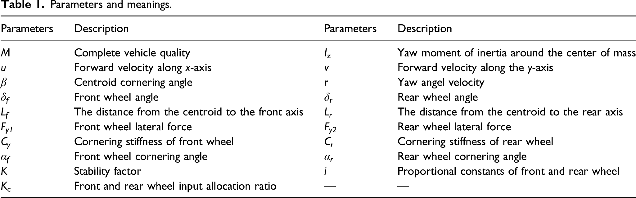
The lateral acceleration of the car is limited to less than 0.4 g, and the tire side deviation characteristic is in the linear range.
11
The 2WS diagram is shown in Figure 1. Two-degree-of-freedom four-wheel steering car model.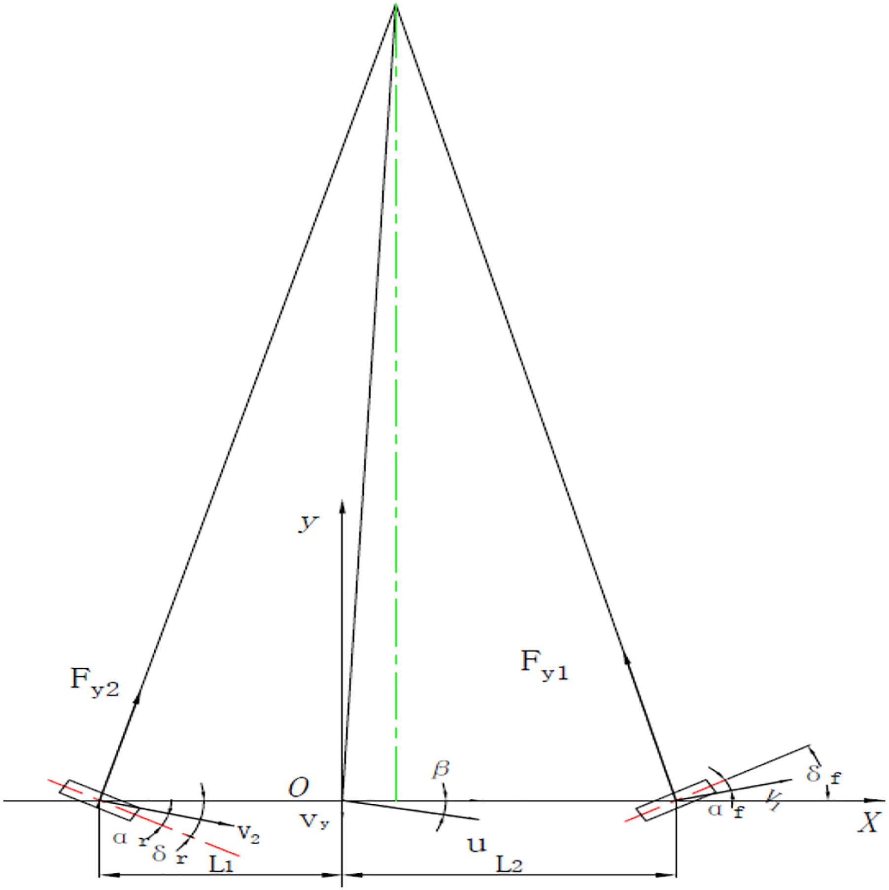
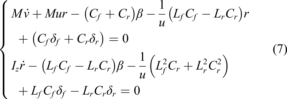
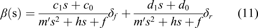
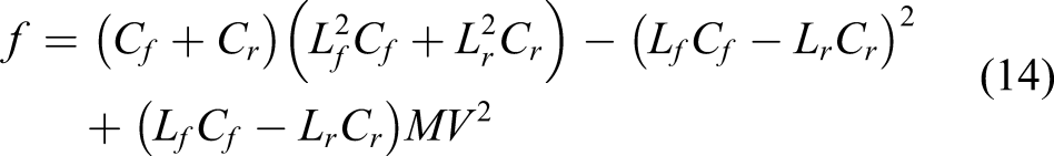
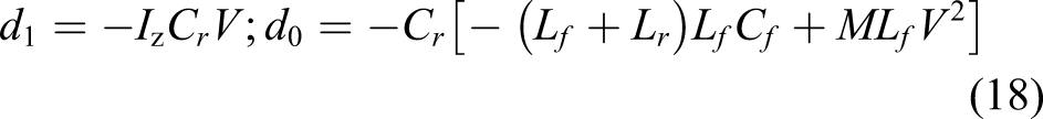
The kinematic differential equation of the model is expressed by formula (1)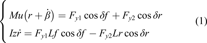
Considering the small rotation angle of the front and rear wheels, it can be approximated that 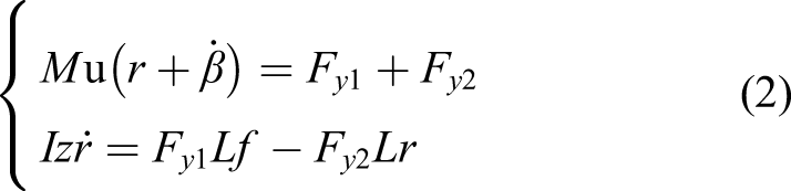


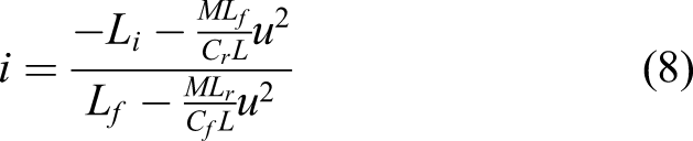
The directional rear wheel steering ratio four wheels steering system was proposed by Sano et al. Use formula (8) to define the front and rear wheels steering ratio i
12
Then, 4WS car rear wheel corner 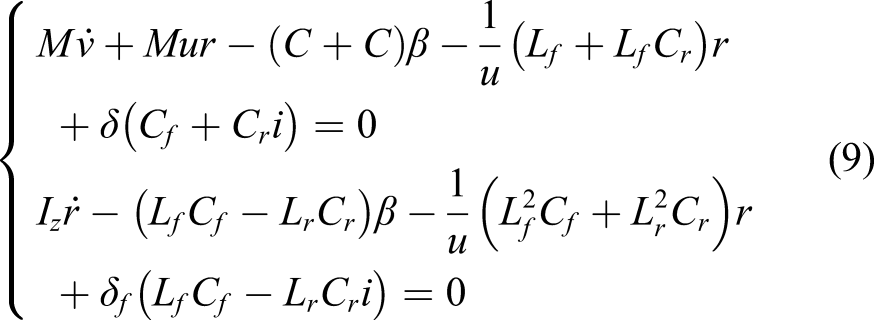


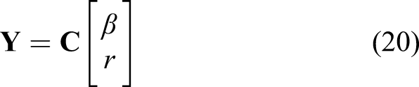
Let the state space of the original system be represented by expressions (19) and (20)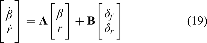
Proceed to the next step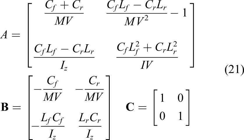
In this paper, the low speed and high speed represented by 30 km/h and 90 km/h are used for system control analysis 13
Balance point analysis of the system
Autonomous systems are represented by expressions (22) and (23)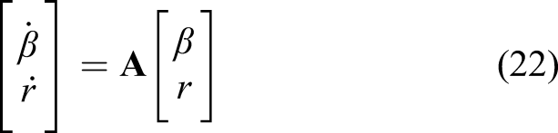
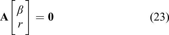
Since the rank of the state matrix A is 2, formula (23) has only a zero solution. The stability of the autonomous system is judged according to Lyapunov first method (indirect method). Substitute 30 km/h into the state matrix to obtain a pair of poles (−1.2551, 1.3044i) and (-1.2551, −1.3044i). The 90 km/h was substituted for the state matrix to obtain a pair of poles (−0.4184, 1.3074i) and (−0.4184, −1.3074i). So the system has a stable zero equilibrium point. The physical meaning is that no matter whether the car is in the steering state at the present moment (the yaw angular velocity or the centroid cornering angle is not zero), the vehicle will eventually reach the straight state at the corner of the front and rear wheels at zero. 14
Analysis of system controllability and observability
When V = 30 km/h, When V = 90 km/h, When V = 30 km/h, When V = 90 km/h,
At almost any speed, the original steering system is fully controlled, observable, and stable. Even if there are certain speed points that do not meet the requirements, it is controllable because the speed cannot be ideally constant. Therefore, the controller can be designed completely.
When the vehicle makes steering action, it will be subjected to the centripetal force pointing to the center of the steering.
6
And, the reaction force of the centripetal force is the friction between the wheel and the road surface. Since the friction force has an upper limit, the yaw velocity cannot be arbitrary. Considering the extreme case, the relation of yaw velocity to speed is expressed by formula (24), where Fr is the maximum friction between the wheel and the pavement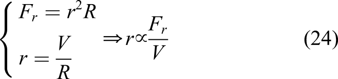
Research on system controller strategy
Design of feedback control for yaw angular velocity
The fixed front and rear wheel steering ratio proposed by Sano is excessively seeking to reduce the yaw angular rate of the car during high-speed steering, resulting in the deterioration of the followability of the rear wheel steering angle. The adjustment effect can only be effective in specific situation , and it can not make full use of maneuverability to enhance its ability, and the method is also with a time lag generally.. In order to improve this deficiency, yaw rate feedback information is added here to achieve readjustment control.
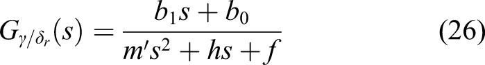
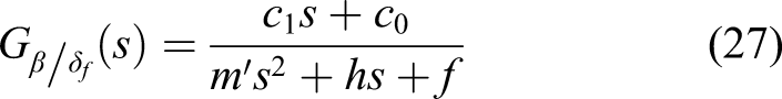
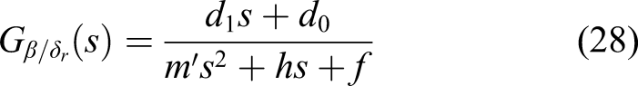
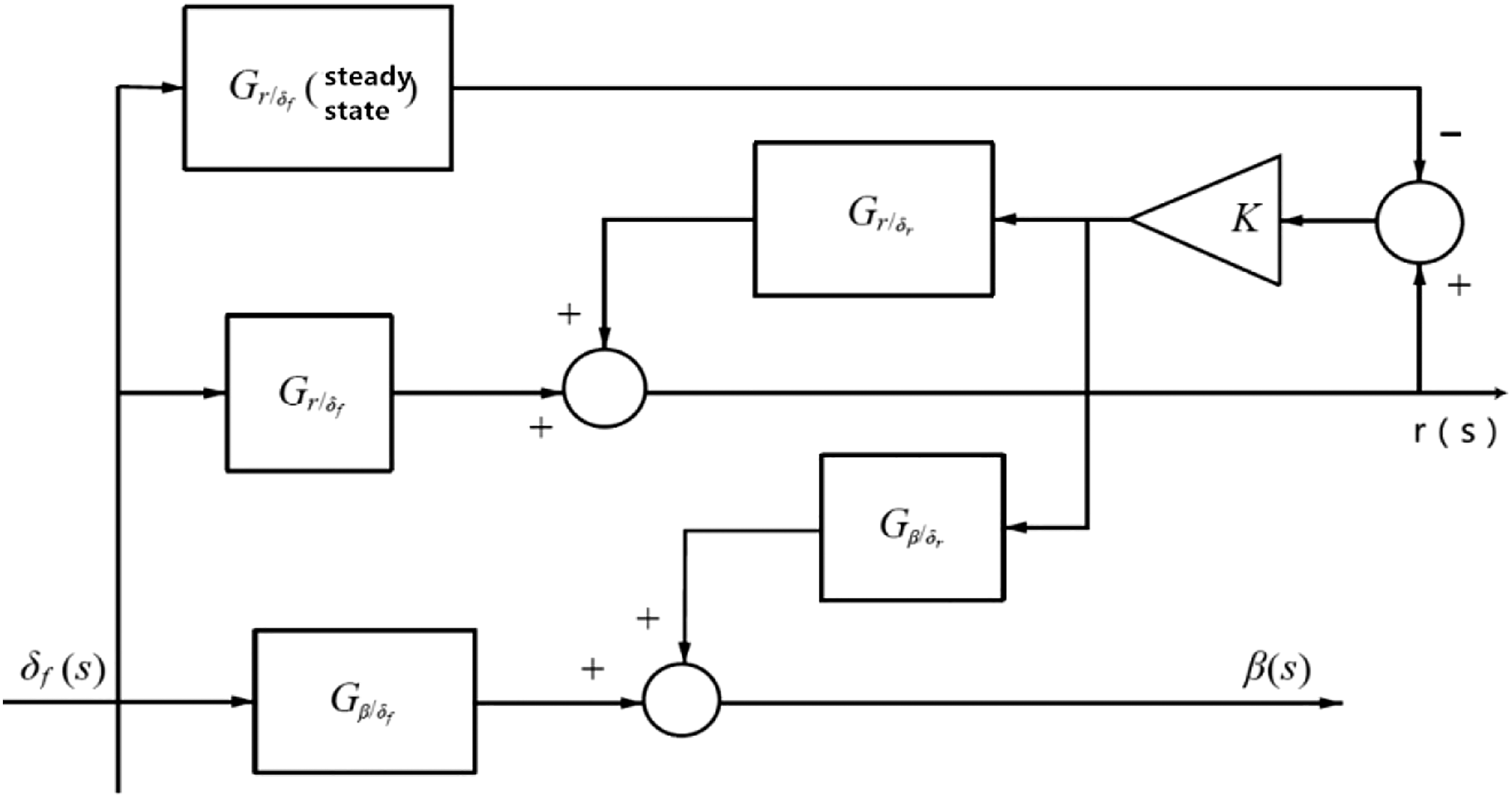
After giving a front rotation angle step input, the rear wheel rotation angle is not directly given according to the current speed, but the corresponding yaw angular velocity response is obtained when the rear wheel rotation angle is ignored, and then compared with the steady-state yaw angular angle velocity, a value to be adjusted is obtained. This value is used to obtain the current need for the rear wheel transverse angle through a certain relationship. This value is used to obtain the current need for the rear wheel transverse angle through a certain relationship. In this whole dynamic process, the rear wheel will be constantly approaching the optimal value as needed.13,14 Its control principle is shown in Figure 2, where each transfers function is calculated by formula (25) to formula (28), respectively Schematic diagram of control based on yaw angular velocity feedback.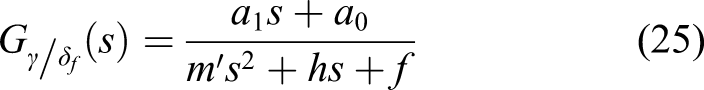
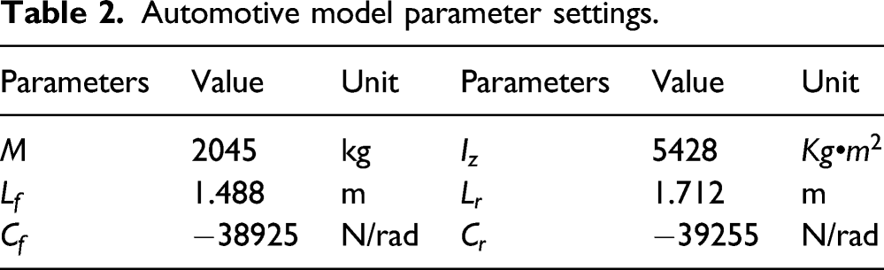
Automotive model parameter settings.
The closed-loop transfer function of the yaw angular velocity is calculated using formula (29)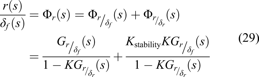
And
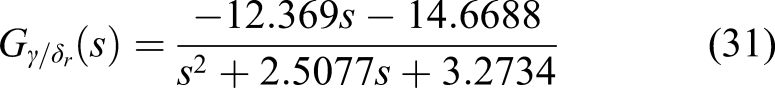
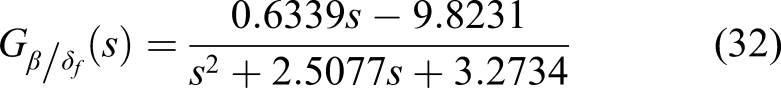
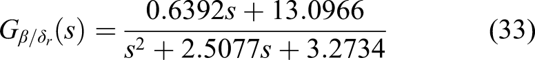
The MATLAB/Simulink system is simulated at low speed (v = 30 km/h). Each transfer function is calculated by formulas (30–33), respectively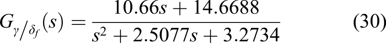
Steady-state yaw angular velocity gain
Model in Simulink is as shown in Figure 3. Simulation model of four-wheel steering system at low speed.
The simulation results are shown in Figure 4. Curve of centroid cornering angle and yaw angular velocity at low speed.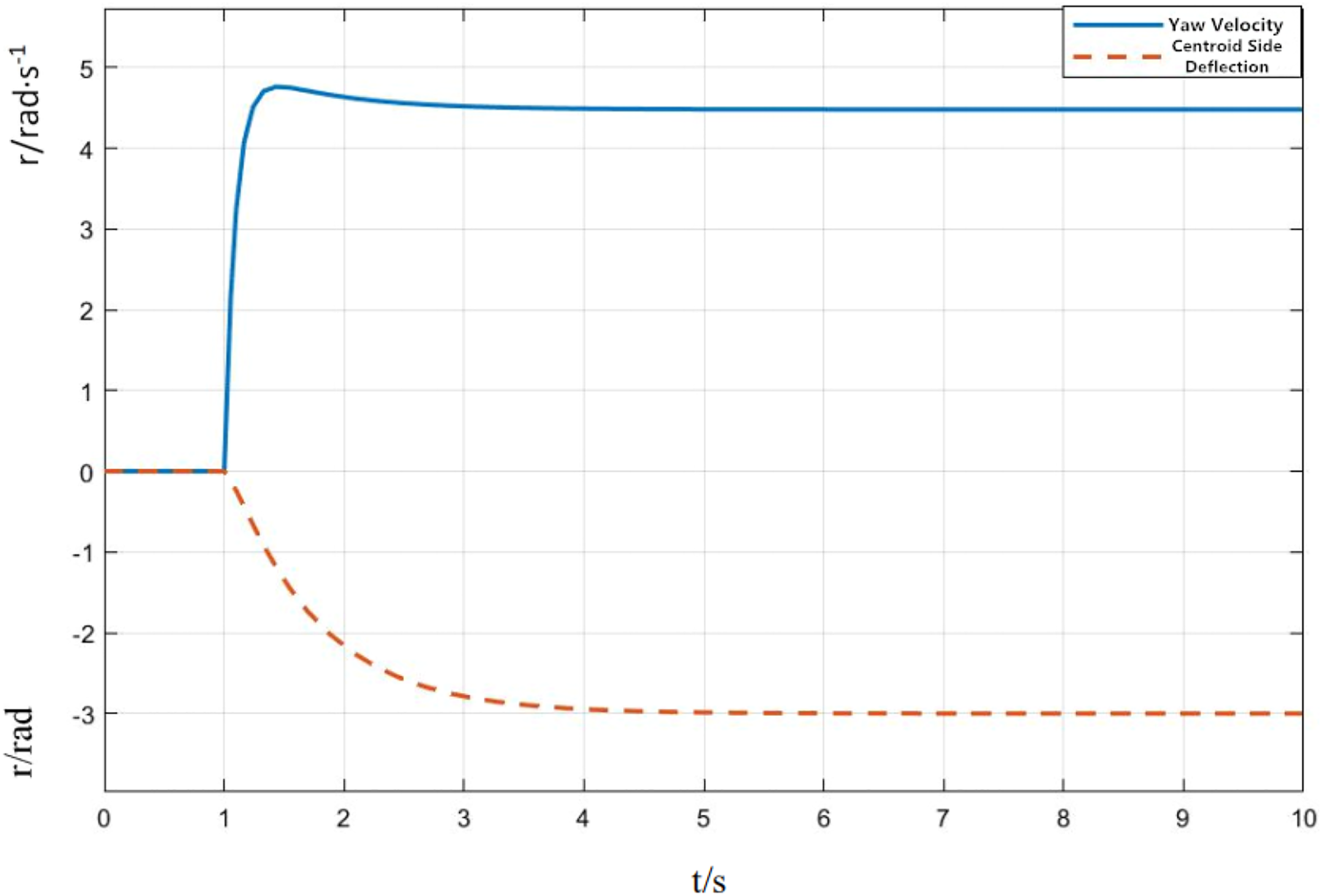
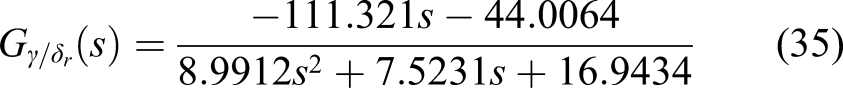
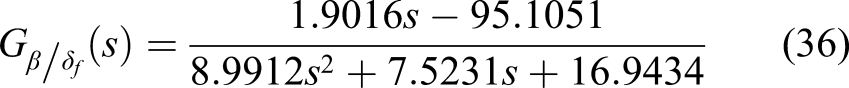
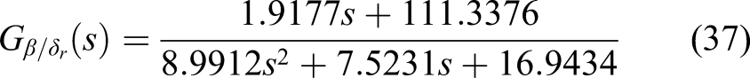
The MATLAB/Simulink system is simulated at high speed (v = 90 km/h). Each transfer function is calculated using formula (34–37), respectively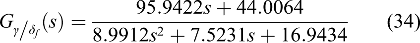
Steady-state yaw angular velocity gain Simulation model of four-wheel steering system at high speed.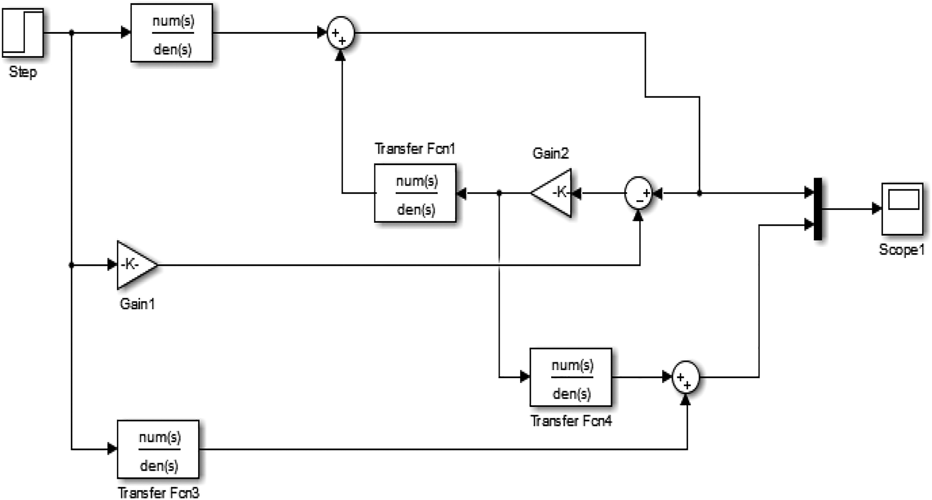
The simulation results are shown in Figure 6. Response curve of yaw angular velocity curve at high speed.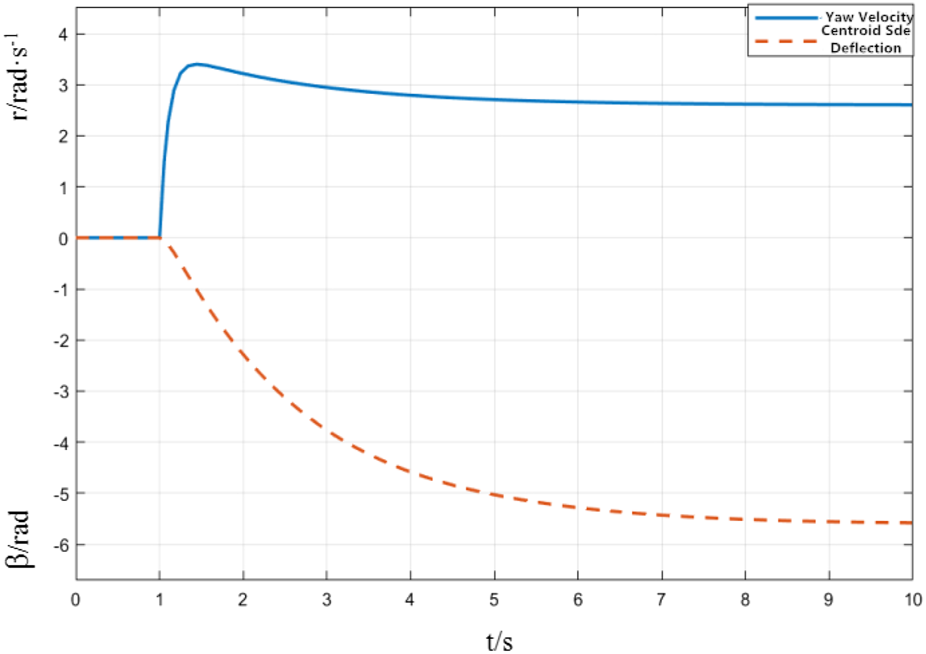
State feedback control design
On the basis of the system without any feedback control (hereinafter referred to as the original system), the dual output controller is used to act on the front and rear wheels, respectively. The control quantity of the controller output is 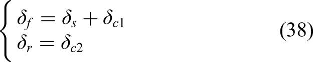
The substitution of formula (38) into formula (19) yields formula (39)
Proceed to the next step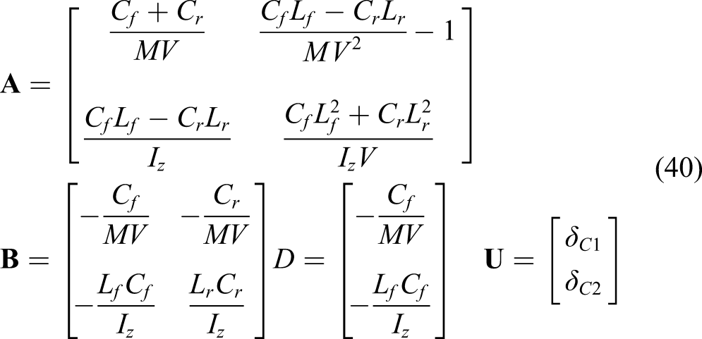
The controller input matrix B is a full-rank matrix, so formula (39) can be transformed into a state equation in the standard form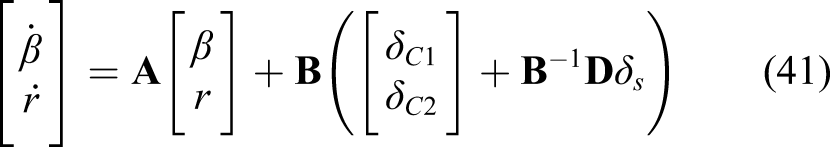
The rank of the controllable matrix 
The state feedback gain matrix
That is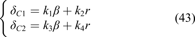
And
When the speed is 30 km/h, the poles of the original system are (−1.2551, 1.3044i) and (−1.2551, −1.3044i), and the desired poles are set to (−2, 0) and (−3, 0) using MATLAB programming to calculate the state feedback gain matrix Response curve of centroid cornering angle and yaw angular velocity at low speed.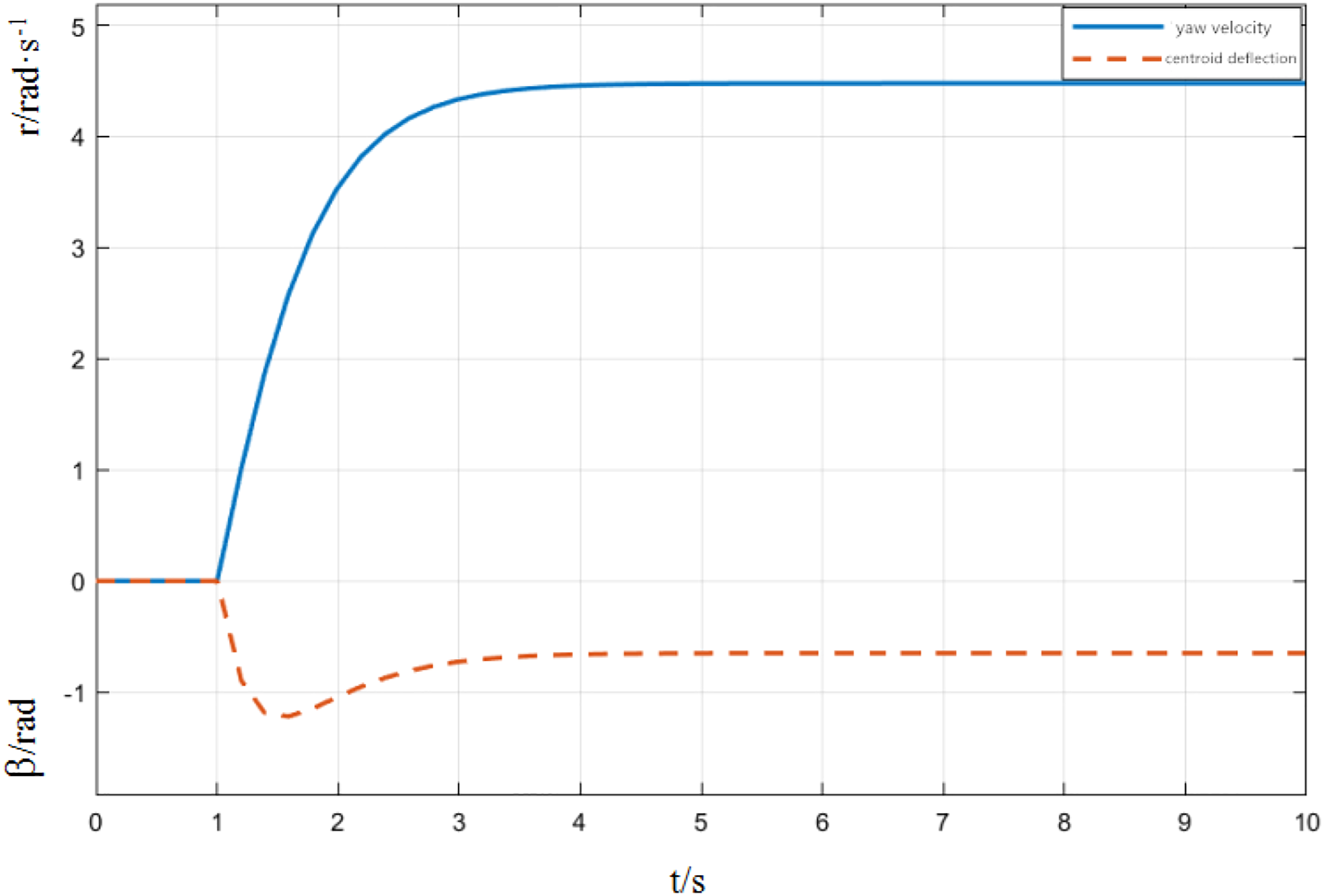
When the speed is 90 km/h, the poles of the original system are (−0.4184, 1.3074i) and (−0.4184, −1.3074i), and the desired poles are set to (−0.6, 0) and (−4, 0) using MATLAB programming to calculate the state feedback gain matrix Response curve of centroid cornering angle and yaw angular velocity at high speed.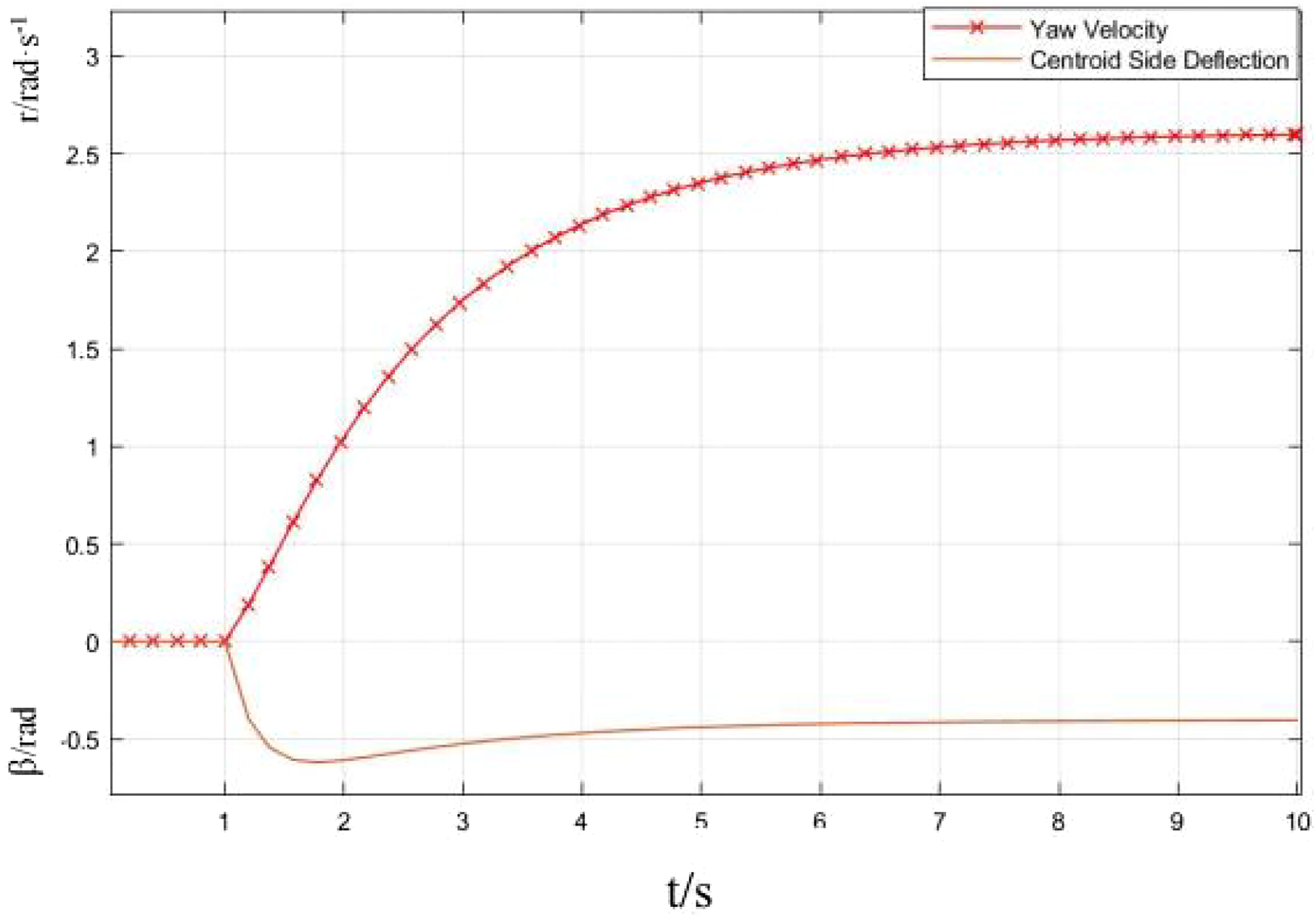
Optimal control strategy
The motion formula indicates that the sum of the front and rear wheel angle mainly affects the lateral motion of the vehicle, and the difference in the front and rear wheel angle mainly affects the transverse motion of the vehicle. Considering the driver's steering operation to control the front wheel rotation angle, the controller controls the front and rear rotation angles according to the information feedback of the vehicle's yaw speed and centroid side deflection angle. 17
The angle of the front and rear wheels can be calculated by formula (45)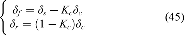
In formula (45),
Selecting the state variable X = β, r]
T
, output Y = β, r]
T
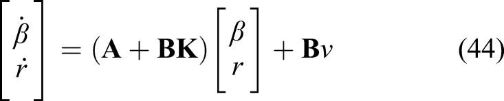
, substituting formula (45) into formula (19), the state equation (46) of the system can be obtained
The coefficients A, B, and D in formula (46) are available in formula (47)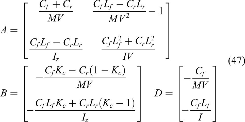
The output formula of the system can be expressed by formula (48)
The coefficient C in formula (46) can be calculated by formula (49)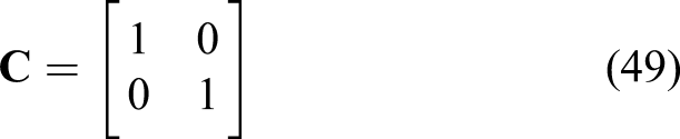
Controllability and observability of the system
In order to realize the optimal control of system stability, we must analyze the controllability and observability of the established system, and judge the controllability and observability of the system by the full rank of the controllability and observability discriminant matrix.
Controllability

Obviously, the controllable discriminant matrix is full rank, so the system is controllable.
Observability
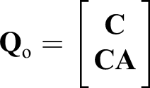
Obviously, the classification matrix is full rank, so the system is appreciable.
Design of quadratic optimal control
The optimal control problem of 4WS is to find an optimal control
It can be considered that the optimal controller of the automobile 4WS is a linear regulator of the end time
The smaller the absolute value of the centroid cornering angle, the smaller the track width of the body sweep when steering. Therefore, reducing the centroid cornering angle is beneficial to enhance the vehicle's capacity for the narrow passage. The performance index of the optimal control takes the quadratic function integral type, and the control goal is to minimize the cornering angle, so the performance index can be calculated by formula (50) 10,11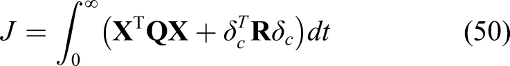
Formula (50)
From the optimal control theory, we can know that if the control input 

The optimal control 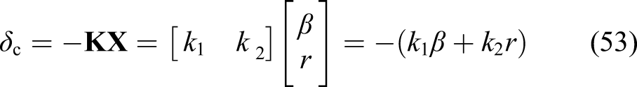
In formula (53),
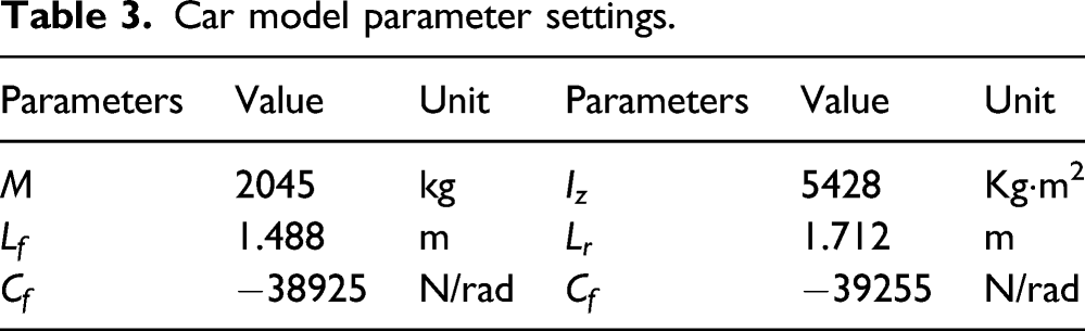
Car model parameter settings.
Using MATLAB/Simulink simulation at low speed (v = 30 km/h), each matrix is calculated as follows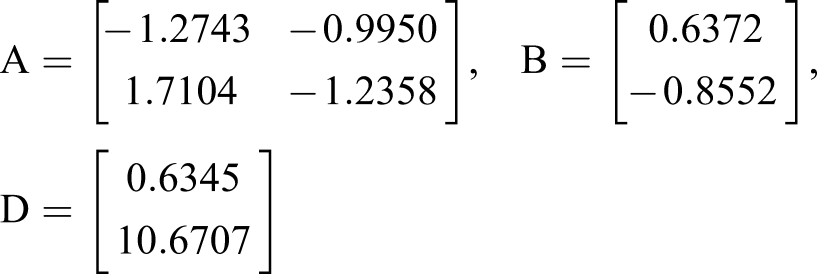
K = [48.0400, −1.4173], the expression for the optimal controller is
The centroid cornering angle and yaw angular velocity response curves can be obtained as shown in Figure 9, respectively. Response curve of the centroid cornering angle and yaw angular velocity at low speed.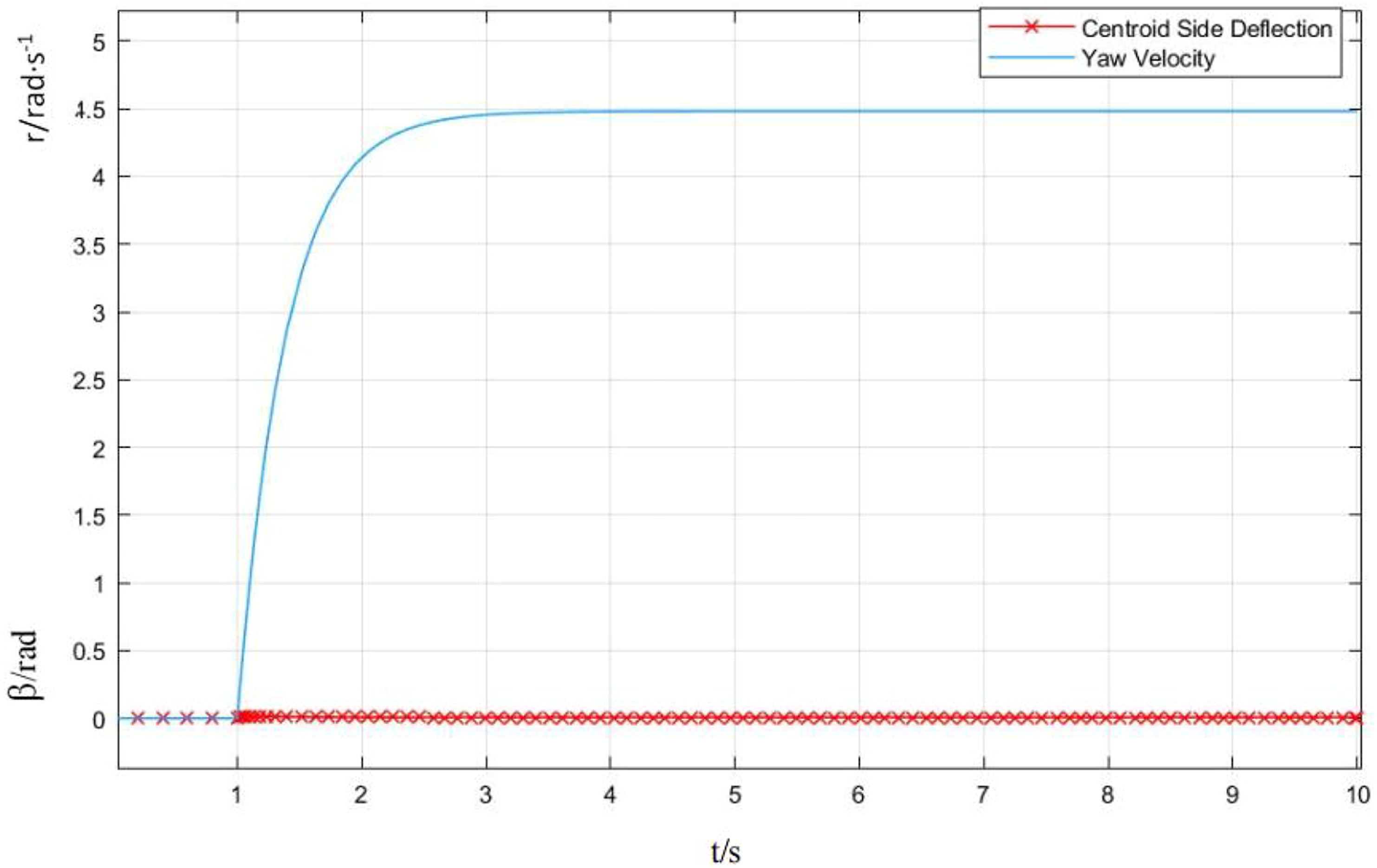
Using MATLAB/Simulink simulation at high speed (v = 90 km/h), each matrix is calculated as follows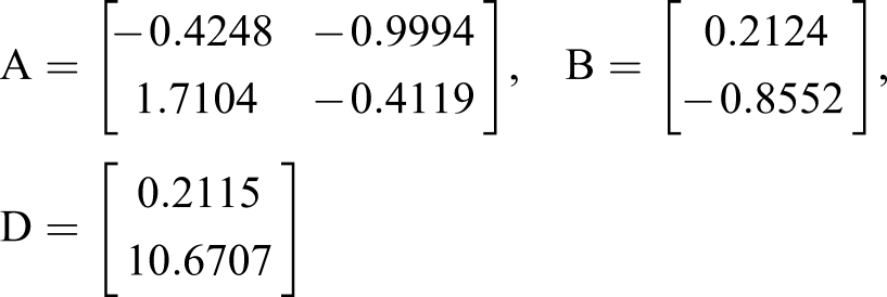
K = [48.0400, −3.7921], the expression for the optimal controller is
The centroid cornering angle and yaw angular velocity response curves can be obtained as shown in Figure 10, respectively Response curve of the centroid cornering angle and yaw angular velocity at high speed.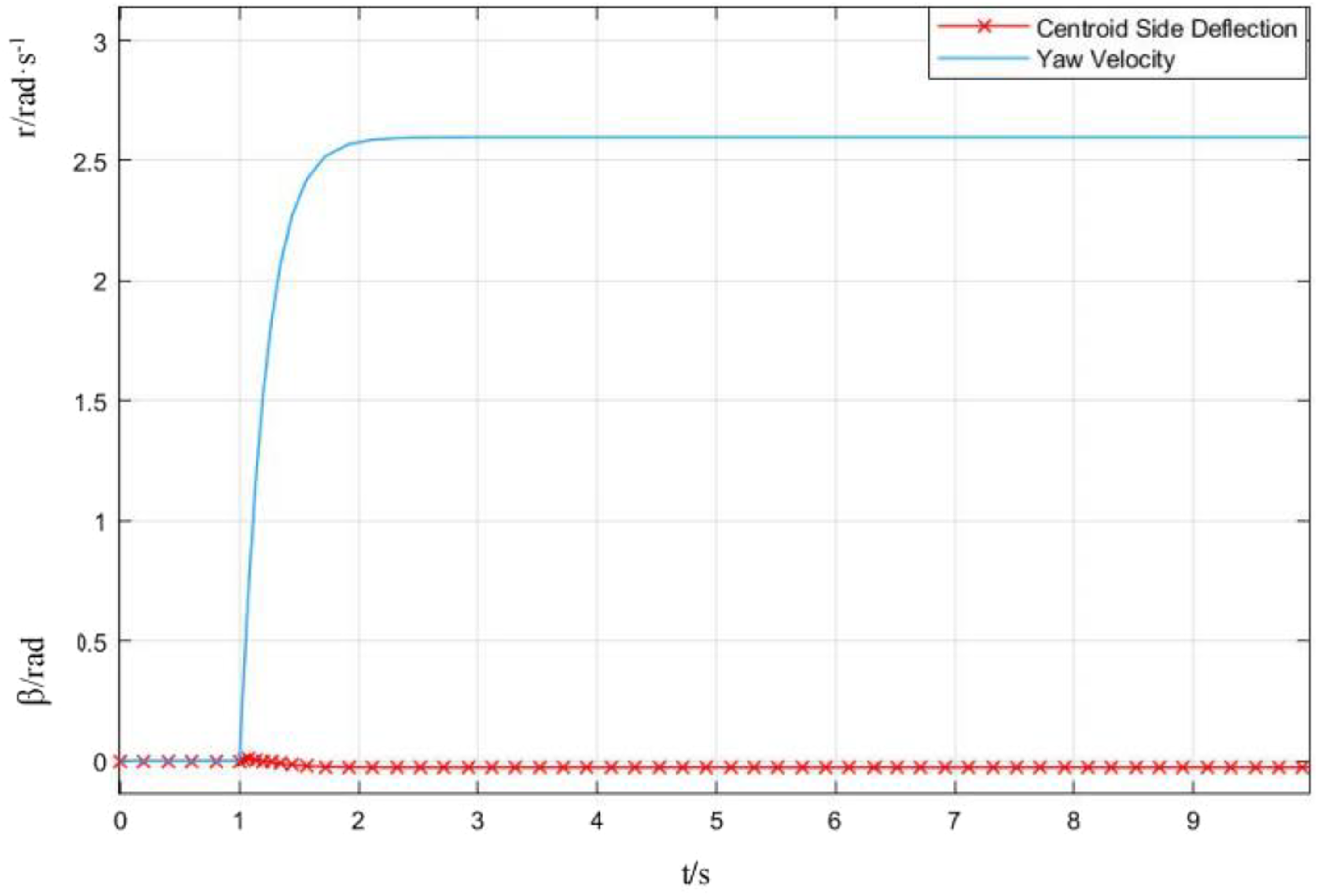
Simulation comparison and analysis of three control modes
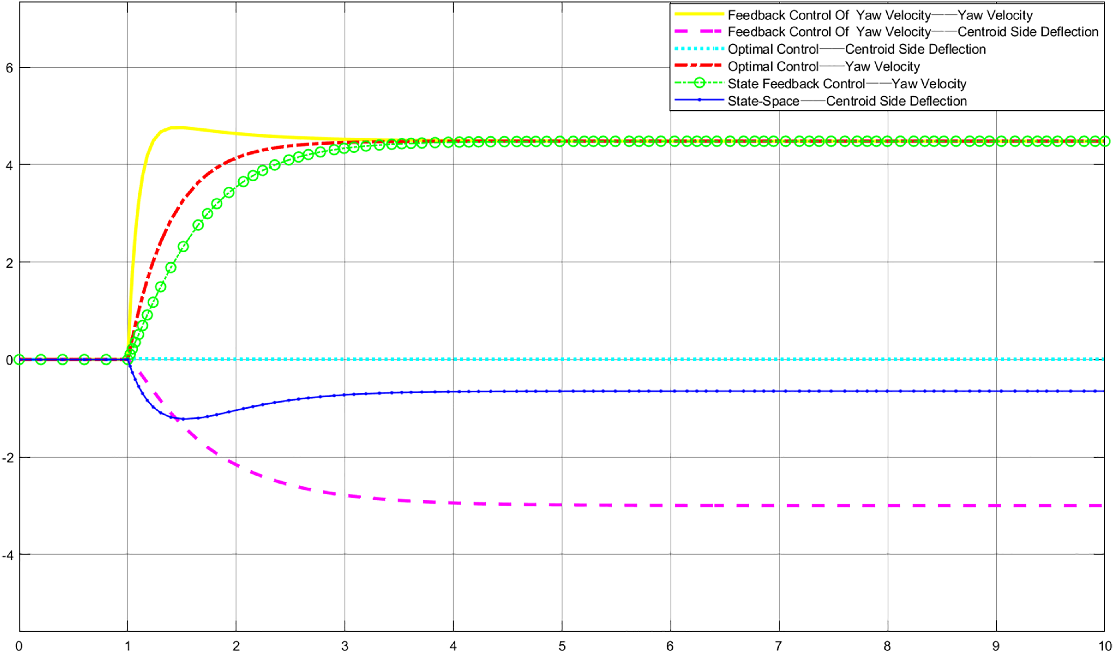
In order to improve the steering stability of 4WS vehicles, three control methods based on yaw angular speed feedback control, state feedback control, and optimal control are used to control the yaw angular speed and the center of mass sideslip angle. The vehicle is simulated in two scenarios of high speed and low speed. According to the results of the simulation, as shown in Figures 11 and 12, the three control methods can make the yaw angular velocity reach a stable state in a short time, and then make the car. The enhanced mobility reflects the advantages of 4WS.
20
The effect of yaw rate feedback control is shown in the figure. Both the overshoot and the time to reach steady-state are well controlled, and the response speed is fast to avoid slippage. However, this method only performs feedback control for the yaw rate. There is no feedback control on the side deviation angle of the center of mass; the pole position of the state feedback can significantly reduce the side deviation angle of the center of mass. Compared with the yaw rate velocity feedback, the overshoot of the yaw rate is eliminated, but the response speed of the state feedback control is the slowest in the three methods which may cause the vehicle to skid; deviation angel of the mass center can be largely improved when adopting quadratic optimal control. During the procedure, it takes short time to reach stability state, and overshoot is reduced obviously, and the movement of the automobile is well controlled. And, the raw rate response of optimal control model is consistent with common model curve controlled by raw rate only, which keeps the original feeling of the driver while turning. In summary, the quadratic optimal control strategy can give full play to the advantages of 4WS. Response curve of the centroid cornering angle and yaw angular velocity at low speed. Response curve of the centroid cornering angle and yaw angular velocity at high speed.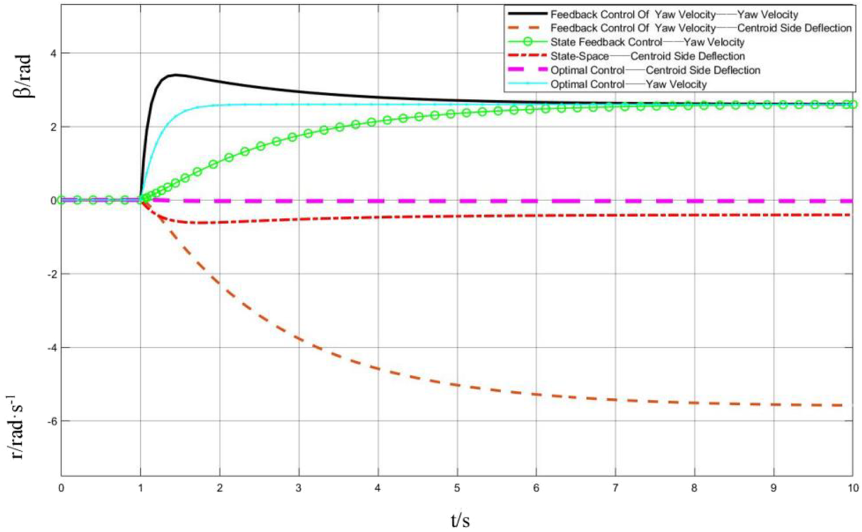
Conclusion
In this paper, the two-degree-of-freedom model of automobile four-wheel steering is established, and the optimal control model of four-wheel steering system is established based on quadratic optimal control theory, so as to optimize the performance index. The driving posture of the vehicle is improved, the goal of zero yaw angle control is realized, and the control error of yaw rate is also very small, so that the vehicle has better driving trajectory, speed maintenance ability and stable state, and further improves the handling performance of the vehicle. This method can effectively ensure the extremely small centroid deviation angle, so that the yaw rate of 4WS car responds quickly, and the driver's steering intention is well realized. At the same time, the desired yaw rate is accurately tracked. However, the optimal control itself seeks the optimal control strategy under the condition of satisfying certain constraints, so that the performance index takes the maximum or minimum value. For a controlled dynamic system, an optimal control scheme is found from a class of allowable control schemes, so that the motion of the system changes from a certain initial state to the target state, and its performance index value is optimal. In general, the optimal control calculated by the maximum principle is a function of time t. Because of this reason, the main disadvantage of this principle is that it cannot eliminate or suppress the disturbance caused by the change of parameters and environment, that is, the robustness needs to be improved. Based on the method proposed in this paper, the next research direction is based on modern variational theory, which is the maximum principle and dynamic programming. According to the classification of control action realization methods, open-loop optimal control and closed-loop optimal control are combined.
This paper is realized by simulation with this method, which makes the front wheel and rear wheel turn in opposite directions when 4WS vehicles run at low speed, thus improving the operability of vehicles; when driving at medium and high speed, the rotation angle direction of the front wheel and the rear wheel can be the same, thus reducing the sideslip and tail swing of the car and improving the handling stability of the car when steering. The latest Mercedes-Benz S-Class car is equipped with a rear axle steering system. Its principle is to install a motor on the rear axle to drive a belt, which can adjust the angle of the rear wheels according to the steering input signal. From this aspect, we can see that we expect the four-wheel steering control system studied to have more applications, from theory to reality.
Footnotes
Declaration of conflicting interests
The author(s) declared no potential conflicts of interest with respect to the research, authorship, and/or publication of this article.
Funding
This research was funded by the National Natural Science Foundation of China, grant number 6192007, 61462008, 61751213, 61866004; the Key projects of Guangxi Natural Science Foundation, grant number 2018GXNSFDA294001,2018GXNSFDA281009; the Natural Science Foundation of Guangxi, grant number 2018GXNSFAA294050, 2017GXNSFAA198365; Scientific Research Project of Education Department of Guangxi Province, grant number YB2014209; Research Fund of Guangxi Key Lab of Multi-source Information Mining & Security, grant number MIMS19-04; 2015 Innovation Team Project of Guangxi University of Science and Technology, grant number gxkjdx201504; College Students' Innovative Entrepreneurial Training, grant number 202110594133, 202110594134; Innovation Project of Guangxi Graduate Education, grant number GKYC202106, GKYC202104, YCSW2021320.