
Abstract
It is well known that a multi-axle wheeled robot possesses larger load capability and also higher drive performance. However, its steering flexibility is degraded due to the large number of wheels. In order to solve this problem, in this article, we proposed three control schemes based on the center of rotation or the steering angles of both the first- and last-axle wheels. To release these control schemes, steering mode selection and also the left wheel’s steering angle in a specific axle are added approaching a practical application. Thereafter, the remaining wheels’ steering angles can be calculated with the Ackerman steering theorem. In order to verify the control effects, a five-axle all-wheel-steering wheeled robot has been developed with the Bluetooth wireless monitor system. Based on the newly designed robot, validation experiments are carried out, such as lateral movement, situ rotation, and multi-mode steering within a narrow space. The results indicate that the proposed design in this article can ensure a more flexible and faster movement within a narrow space. It shows large potential in obstacle avoidance compared with the conventional partial-wheel steering mode.
Introduction
A multi-axle wheeled robot consists of more than two axles as shown in Figure 1, and all wheels can drive independently. Its maneuverability and mobility are excellent. Its load ability is very strong on extreme terrains and obstacles. Therefore, it is preferred for off-road operations. Compared with a conventional two-axle four-wheeled robot, the multi-axle robot is quite suitable for field rescue, disaster search and rescue, and other non-road situations. However, because of its large size and huge number of wheels, the steering flexibility and control are intricate, especially when the robot is moving in a narrow space.

A multi-axle wheeled robot uses the skid-steer mode.
By far rare academia is working on the multi-axle steering of the wheeled robot except the two-axle robotic steering system.
In general, there are focuses, that is, the skid-steer 1 and the car-like Ackerman steer. Skid-steer robots are turned by adjusting the speed of the left- and right-side tracks or wheels as shown in Figure 1. At the extreme situation, such as the left and right sides have opposite speeds, skid-steer robots are able to turn in place, and it provides useful mobility in tight spaces during teleoperation.2,3 Car-like Ackerman steer robots is turned by controlling steering wheels’ angle. Skid-steer mode is adopted in most crawlers and some wheeled robots.4,5 Although skid-steer mode can simplify steering system structure, it has high energy consumption and serious tire wear for its large steering resistance and large size. 6 Moreover, the accuracy of the chassis position,7–10 which is relatively significant for robot control, cannot be promised. This further restricts the lateral movement of the skid-steer mode. It is also very important for the robot to move precisely and quickly, especially in the battlefield quick explosive ordnance disposal (EOD) and rescue.
On the other hand, the car-like steer mode has many advantages, such as low steering resistance and road damage. Researches are mainly focused on the path control of the wheeled robot.11–14 Watanabe et al. 15 and Gao and Li 16 presented a mathematical model for multi-axle vehicles operating on level ground, and the basic turning characteristics were analyzed. Pitkänen et al. 17 presented a general method for synchronizing the turning and steering rates of a mobile robot’s wheels. Choi and Ryew 18 developed a robotic system with active steering capability for internal inspection of urban gas pipelines. Williams 19 developed a generalized model to analyze multi-axle vehicle characteristic. Kim et al. 20 discussed the improvement of the cornering performance and maneuverability of 6WD/6WS mobile platform using independent wheel torque and independent steering on each wheel. These studies are mainly focused on the robot trajectory and steering performance control. However, controlling all the wheel’s steering angle has not been studied yet for the sake of accurate and flexible robots posture adjustment, especially for multi-axle robots.
For the purpose of a high mobility and flexibility in wheeled robots design, one has to solve the following problems, such as controlling wheel’s steering angle and adjusting the robot position in restricted space fast. Therefore, if we can propose special schemes to steer all wheels, the robot can move freely toward any direction and also can change its posture quickly. Thus, the steering angle of each wheel should be well controlled. For the simplicity of the application, less control variables are preferred.
Consequently, we proposed a new steering control strategy and system to realize multi-axle all-wheel-steering with the least control variables.
The remaining sections of this article are organized as follows: in the second section, the steering principle of various wheeled robot is analyzed to determine control parameters. Then, the control variables and implementation are proposed. In the third section, a five-axle all-wheel-steering and all-wheel-drive wheeled robot system is developed following the chassis mechanism; furthermore, control circuit and software modules are designed. In the fourth section, steering experiments are carried out and analyzed to verify whether the robot can travel along the required route. Finally, conclusions of this article are presented in the fifth section.
Steering control analysis
Wheels move around in the same instantaneous center of rotation whether they are for a two-axle- or multi-axle-wheeled robot. This mechanism ensures that all wheels are in a pure rolling condition and will not slip or slippage is reduced to a minimum during steering. The turning radius of each wheel is different. Thus, the steering angles of the inner and outer wheels on the same axle are different, including the same sides of the wheels on different axles. The wheels should be consistent with the theoretical calculation of a proportional relationship.
Steering principle of a multi-wheeled robot chassis
Two-axle and two-wheel-steering wheeled robot chassis
As shown in Figure 2, when the two front wheels of a two-axle wheeled robot are steering, the axis of the two front wheels should intersect with the rear axle at point O. 21 The steering angle relationship between the outside front wheel and the inside front wheel should satisfy the following Ackerman equation
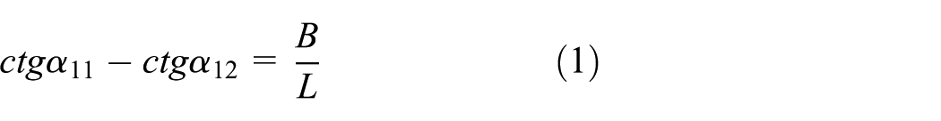
where α11 and α12 are the steering angles of the outside wheel and the inside wheel in the first axle, respectively; B is the distance of the intersection between the centerline of two kingpins and the ground; and L is the wheelbase.

Ideal relationship of the steering angles between the two front wheels of a two-axle wheeled robot during steering.
Two-axle and four-wheel-steering wheeled robot chassis
As shown in Figures 3 and 4, when the four wheels of a two-axle wheeled robot are steering, the axis of the two front wheels should intersect with those of the two rear wheels at point O.22–24 Therefore, each wheel should not only meet the relationship between the right and left wheels but should also satisfy the relationship between the front and rear wheels

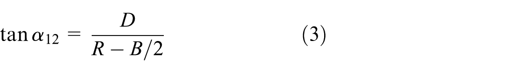
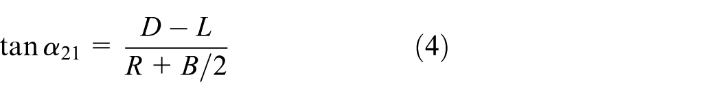
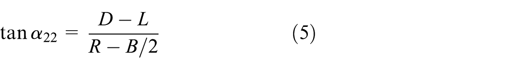
where D is the distance from rotation center O to the first axle. If O is behind the first axle, as shown in Figures 3 and 4, D is positive. R is the distance from O to the longitudinal centerline of the robot. The steering angles of the outside wheel and inside wheel in the second axle are denoted by α21 and α22, respectively.

Ideal relationship of the angles between the two sides of steering wheels of a two-axle four-wheel-steering wheeled robot during in-phase steering.

Ideal relationship of the angle between the two sides of steering wheels of a two-axle four-wheel-steering wheeled robot during adverse-phase steering.
Equations (2)–(5) show that the angle of every wheel can be changed when D and R are changed. Hence, D and R can be used to control robot steering. Figure 3 illustrates that all wheels turn in the same direction when O is behind the second axle. This process is known as the in-phase steering mode. When O is between the first and second axle as shown in Figure 4, the direction of the steering wheels between the first axle and the second axle is contradictory. This process is known as the adverse-phase steering mode.
Multi-axle all-wheel-steering wheeled robot chassis
According to Ackerman’s theorem, which is shown in Figures 5 and 6, the following equations are employed when the multi-axle robot chassis is steering


where αi1 and αi2 are the steering angles of the left and right wheels in the ith axle, respectively. When the wheels are steering counterclockwise, the angle is positive; otherwise, it is negative. i = 1, 2, …, n, where n is the number of robot axles, and Lj is the distance between the jth axle and the (j + 1)th axle. Equations (6) and (7) indicate that the steering angle of every wheel can be calculated if D and R are given.
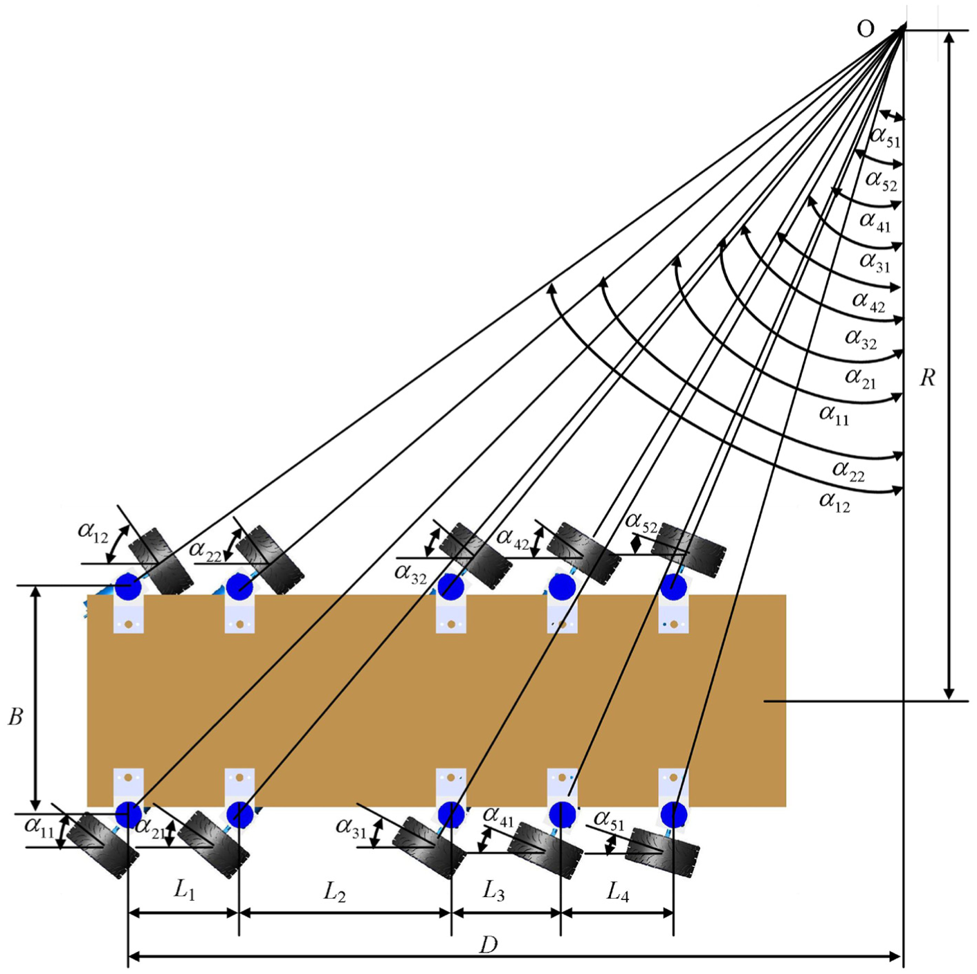
Ideal relationship of the wheels’ steering angle between both sides in a multi-axle all-wheel in-phase steering robot.

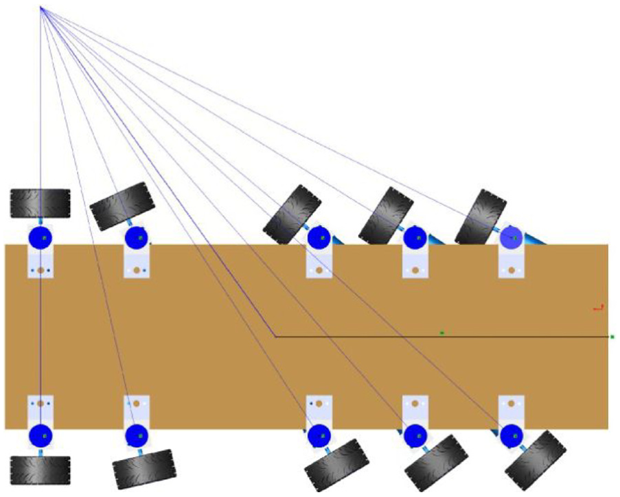
Ideal relationship of the wheels’ steering angle between both sides in a multi-axle all-wheel adverse-phase steering robot.
Control scheme of a multi-axle steering robot
Depending on the using situation, the chassis of a wheeled robot requires certain types of steering modes, namely, in-phase steering, adverse-phase steering, non-steering first-axle wheel mode (rear part of the wheeled robot swings), non-steering last-axle wheel mode (front part of the wheeled robot swings), and situ rotation (zero turning radius). These modes are illustrated in Figures 5–9. Using the in-wheel motor, the drive torque of every wheel can be controlled separately to improve steering agility and flexibility. Three steering control schemes are proposed on the basis of these requirements:
Steering control scheme based on rotation center (RC). Figures 5 and 6 and equations (6) and (7) show that if the geometric parameters of the robot are certain, the position of the rotation center O can be changed by changing α11 and D. Therefore, the value of R and the steering angles of other wheels can be calculated according to D, α11, and the geometric parameters of the robot. This process enables switching from different steering modes. However, this control scheme cannot be implemented when the wheels in the first axle fail to steer while the other axles are steering.
Steering control scheme based on the steering angles of the left wheel in the first and last axle (AFL). According to equations (6) and (7), the input variables are changed to α11 and αn1, which indicate the steering angles in the first and last axles, respectively. D and R, as well as the steering angles of the other wheels, can be calculated. The steering angle of every wheel can be controlled through this mechanism.
Improved RC. An operator only has two hands for controlling the steering angle and traveling velocity of the robot. The AFL scheme cannot be controlled easily with only one hand. Therefore, we employ the improved RC scheme as the control scheme in actual control. We use the RC strategy when the first axle steers. We continue to use the RC strategy when the first axle fails to steer and α11 is replaced by αn1. This process is known as the improved RC steering strategy.
Non-steering first-axle wheel mode.

Non-steering last-axle wheel mode.

Situ rotation mode.
The input variables in equations (6) and (7) are D and α11 (if the first axle steers) or αn1 (if the first axle does not steer but the last axle steers). R and the steering angles of other wheels can be calculated. The steering angles of every wheel can be controlled through this equation.
Implementation of steering modes
Six kinds of steering modes are proposed that can be chosen by a mode selection switch. The steering mode selection switch is used to input D. The value of D is already given in every steering mode:
In-phase steering mode. If
Adverse-phase steering mode. If
Non-steering first-axle wheel mode.
Figure 7 shows that if
Non-steering last-axle wheel mode. As illustrated in Figure 8, if
Lateral travel mode. If
Situ rotation mode. If
Except for Mode (3) (non-steering first-axle wheel mode), the remaining steering modes can all be controlled by α11 and D. Mode (3) can also be controlled by αn1 and D.
In actual control, the operator can input α11 (or αn1 in steering Mode (3)) through the steering wheel and input D through the steering mode selection switch. This process can be realized through the improved RC control strategy. Thus, when the steering mode is selected by the user, α11 or αn1 is obtained by the steering wheel. The steering angle of other wheels can then be calculated according to equations (6) and (7). Figure 10 presents the steering flowchart.

Steering flowchart.
Electric wheel differential drive control that corresponds to each steering mode
When the robot uses steering Modes (1)–(5), the driving torques of the wheels are equal and in the same direction. When the robot uses steering Mode (6), the driving torques of the right and left sides of the wheels are equal and opposite.
Design of the mechanical system of a five-axle all-wheel-steering wheeled robot
Steering structures
The overall structure of the five-axle all-wheel-steering and all-wheel-driving wheeled robot consists of a body, 10 steering mechanisms, 10 wheel drive mechanisms, a battery pack, 5 motor drivers, and a robot electronic control unit (ECU). The structure is illustrated in Figures 11–13. Table 1 shows the parameters of the wheel drive motor LT25GA98-280 in a wheeled robot. Figure 14 shows the prototype of a five-axle wheeled robot chassis.

Overall structure of a five-axle all-wheel-steering wheeled robot.

Steering mechanism.

Wheel drive mechanism.
Parameters of the wheeled robot drive motor LT25GA98-280.


Five-axle wheeled robot prototype.
Steering system hardware
The whole ECU is composed of three single chips STC12C5A60S2. This system has a 10-wheel drive motor control, 10 steering servo motor controls, a 10-wheel speed acquisition (with speed sensor at every wheel to detect the wheel’s rolling speed), electronic throttle acquisition, steering wheel angle acquisition, and serial communication with a Bluetooth module. Figure 15 shows the components of the system architecture. The Bluetooth module is responsible for the serial communication between the single chip and a notebook computer.

Hardware structure of the five-axle all-wheel-steering wheeled robot.
Steering system software
An operator can select the steering mode and control travel speed and direction according to the required travel path. The steering angle of every wheel, as well as the speed and traveling direction, can be calculated after the notebook acquires these operation instructions. These instructions are then transmitted to the robot ECU through the Bluetooth module. Thus, the steering servo motors and wheel drive motors can be controlled to conduct the specific steering mode and the electronic differential speed driving control as shown in Figure 16. The control program in the notebook is developed using LabVIEW to achieve steering and speed control.

Software structure of a five-axle all-wheel-steering wheeled robot in the ECU and a notebook computer.
Based on the requirements, the system includes the following subsystems:
Steering/speed control subsystem includes the following major modules:
Steering angle control sub-module. According to the requirement of robot steering, the following modes can be chosen by the steering mode selection switch: left lateral travel, right lateral travel, situ rotation, non-steering first-axle wheel mode, non-steering last-axle wheel mode, adverse-phase steering, and in-phase steering. According to the steering wheel angle and the structural parameters of the robot chassis, the steering angles of other wheels can be calculated using the Ackerman theorem. This process can ensure that all wheels are in pure rolling state, wheel slips are minimized, and tire wear and driving resistance are reduced.
Wheel torque control sub-module. According to the requirements of the robot steering control, the speed and the driving torque of each wheel are controlled to achieve electronic differential speed and to avoid wheel sliding.
Information collection and dissemination subsystem. The steering angle, electronic throttle, and speed information of every wheel are collected. Steering control information from the notebook is sent to the robot ECU.
User interface subsystem. This subsystem is employed by the user to control the robot (e.g. steering mode, traveling speed, traveling direction, and steering angle) and to display the chassis running parameters (e.g. every wheel’s angle and speed).
Steering implementation subsystem. The robot ECU controls the steering servo motor of every wheel to enable the wheels to turn to a certain angle according to the steering information from the notebook.
Electronic differential execution subsystem. This subsystem controls each wheel to enable them to travel with determined speed and to prevent tire slip.
Experiment
Lateral travel, situ rotation, and multi-mode steering experiments were conducted in the narrow space through the developed five-axle wheeled robot to verify the proposed steering modes. This process is illustrated in Figures 17–24. A driver can change the steering mode through the steering mode switch according to the steering requirement.

The robot C moves laterally into position between the robots A and B.

Experiment pictures of traveling laterally into position. The turn is from 1 to 9.

Robot C moves laterally out of the position between robots A and B.

Experiment pictures of traveling laterally out of the position. The turn is from 1 to 9.
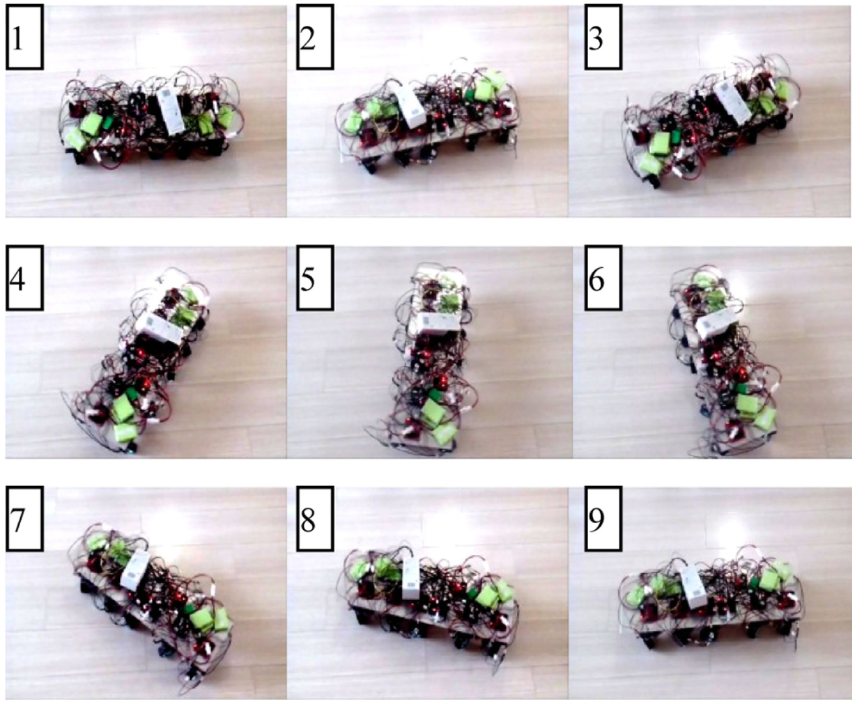
Situ rotation experiment pictures. The turn is from 1 to 9.
Multi-mode steering in a narrow space.
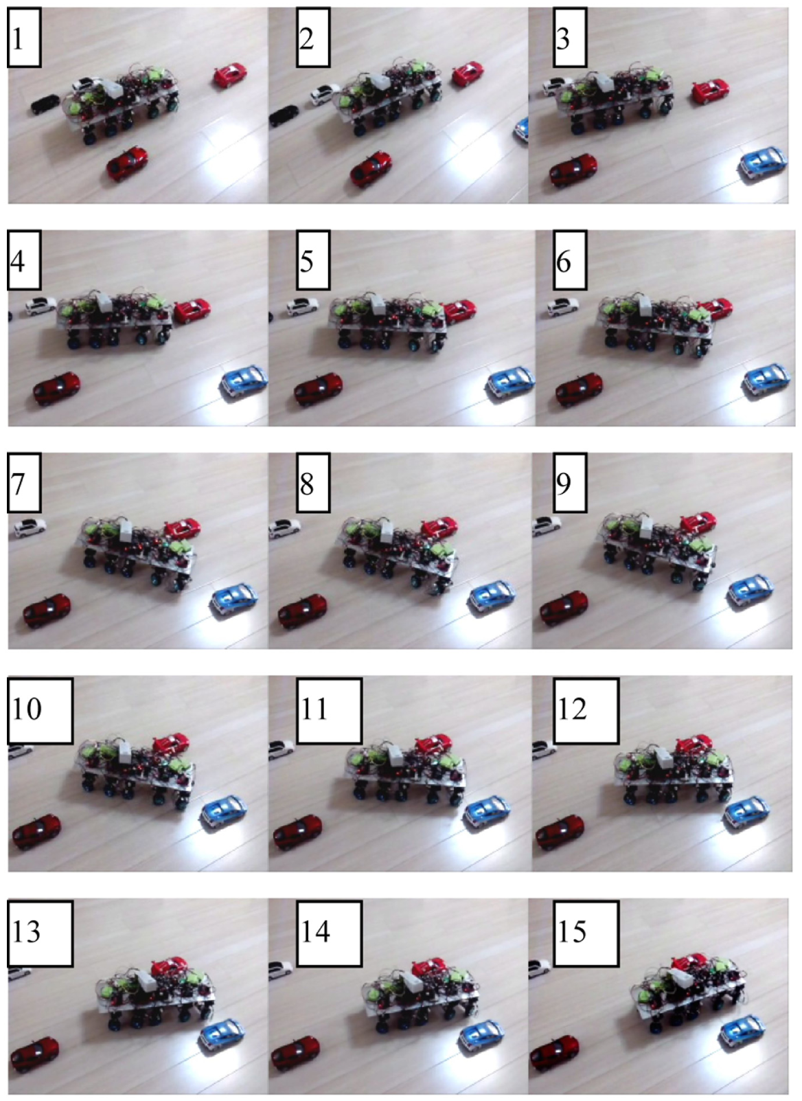
Pictures of the multi-mode steering experiment in a narrow space. The turn is from 1 to 15.

Trajectory of a wheeled robot while traveling in a narrow space.
Figures 17 and 18 show that all wheels turn left at 90° during the lateral travel mode. Robot C can move easily into position between robots A and B. This movement is convenient.
Figures 19 and 20 show that all wheels turn right at 90°. Robot C can move quickly out of the position between robots A and B.
Figure 21 shows that the left and right wheels can be driven in the opposite direction when using the situ rotation mode and that the robot can perform a zero radius swing.
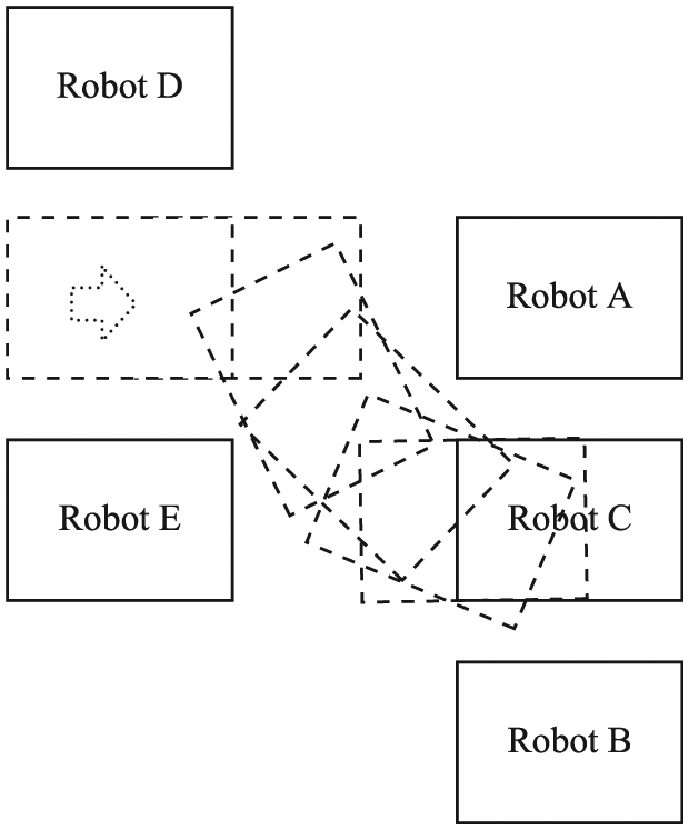
Figures 22 and 23 show that robot C can enter a small space between robots A, B, D, and E using the adverse-phase steering mode. The trajectories are shown in curves 1 and 2 in Figure 24. A conventional, front-only, two-axle-steering (partial-wheel-steering mode) robot can travel into the narrow space between A, B, D, and E. However, this robot collides with A, B, D, and E, as shown in curves 3 and 4 in Figure 24. An all-wheel steering robot only needs a small space to complete a particular track easily. However, this task is difficult for a conventional robot with partial-wheel steering. This finding is important for disaster relief in limited space. Table 2 shows the contradictory steering performance. Excluding structural complexity, our new steering mode (all-wheel-steering multi-mode steering) has the best performance.
Steering performance comparison.

Conclusion
To improve the flexibility of multi-axle wheeled robot steering, three new control strategies were proposed through the principle analysis of multi-axle steering wheeled robots. These strategies are based on the center of rotation or the steering angles of wheels.
To meet the requirement of practical use, we proposed the use of a left-wheel steering angle in the first or last axle and the steering mode selection switch as the control variables. Six steering modes were proposed on the basis of this approach. To investigate steering performance, a five-axle all-wheel-steering and all-wheel-drive wheeled robot prototype was developed with the Bluetooth wireless system. The experiments showed that the five-axle wheeled robot could efficiently complete the specified track in a narrow space using the proposed steering mode. This robot can also achieve a more flexible control of the robot posture than the conventional partial-wheel steering mode.
Footnotes
Acknowledgements
The authors would like to express their thanks to the anonymous referees for their valuable comments.
Academic Editor: Yong Chen
Declaration of conflicting interests
The author(s) declared no potential conflicts of interest with respect to the research, authorship, and/or publication of this article.
Funding
The author(s) disclosed receipt of the following financial support for the research, authorship, and/or publication of this article: This work was supported by National Natural Science Foundation of China (51005128), Qingdao Technological University Dr. Scientific Research Foundation (C2007-091), and Shandong Province colleges and universities outstanding backbone teacher international cooperation and cultivation projects.