
Abstract
Wireless sensor networks consist of hundreds or thousands of nodes with limited energy resources, and thus, efficient use of energy is necessary for these networks. Given that transmissions are the most energy-demanding operation, routing algorithms should consider efficient use of transmissions in their designs in order to extend the network lifetime. To tackle these challenges, a centralized algorithm is proposed, called improved continuous enhancement routing (ICER), for computing routing trees of refined quality, based on data aggregation while being aware of the battery energy state. Comparisons between ICER and other known solutions in the literature are performed. Our experiments show that ICER is able to ensure, on average, the survival of 99.6% and the connectivity of 99.3% of the network nodes compared to 90.2% and 72.4% in relation to the best-compared algorithm. The obtained results show that ICER significantly extends the network lifetime while maintaining the quality of the routing tree.
Keywords
Introduction
Wireless sensor networks (WSNs) are a special kind of ad hoc network that relies on spatially distributed autonomous devices which measure many types of physical quantities such as temperature, pressure, and pollutants. WSNs are used for defense purposes, 1 environmental monitoring, communications, industry, 2 and agriculture, 3 among other applications that can be critical to saving lives and assets.
The architecture of a WSN varies according to its application. For instance, a typical layout is to consider a hierarchical network with some nodes that have better communication capabilities, such as better amplifiers for reaching longer distances and sometimes even without energy restrictions, referred to as gateways. The common sensor nodes collect data but have a smaller radius of communication and limited battery. The sink is a node that centralizes all the gathered data and works as an interface between the network and the application. In some scenarios, gateways can directly reach the sink. In this article, another conventional layout is taken into account, which is to consider all the nodes with the same communication capabilities; therefore, the only way to reach the sink is in a multi-hop fashion. The intermediate sensor nodes used to transmit data to the sink, in this case, are called relay nodes. The source nodes are the ones that sense the data that have to be delivered to the sink.
It is desirable that the lifetime of the network be extended as much as possible so that the expenses on network maintenance are reduced. For this reason, WSN routing algorithms should consider energy consumption. In particular, transmission, which is the most energy-consuming operation, 4 has to be carefully handled by the routing algorithm.
When nodes have the same capabilities, the network is said to be homogeneous, that is, all the devices are of the same type. However, when the network consists of different types of devices, the network is said to be heterogeneous. For instance, in a scenario where the gateways have no restrictions on energy, they can be heavily used for routing, unlike a homogeneous scenario where the energy expenses have to be balanced to maximize the network lifetime.
In order to endure the network lifetime, in-network data aggregation has been used. The relay nodes, instead of just transmitting the raw data, can aggregate the data reducing the number of transmitted packets. The nodes that perform aggregation are called aggregation nodes. This scheme often reduces the energy consumption. In addition, the battery level of the nodes is taken into account to compute the routing tree. Namely, the design builds routing trees prioritizing nodes with high battery levels available while balancing the number of nodes used. Nonetheless, as the network operates, the nodes that are part of the routing tree consume their battery; therefore, the algorithm dynamically changes the routing tree to avoid a complete depletion of the node batteries. The dynamically built routing tree may be larger than the previous one, but it distributes the energy consumption throughout the network. It is clear that bigger trees have greater delivery times, which may have a negative impact on the application. For that reason, the proposed algorithm has parameters to tweak the trade-off between the size of the routing tree and the battery usage.
Based on these considerations, improved continuous enhancement routing (ICER) is proposed. The solution starts by gathering the network topology and centralizing it into the sink; then, the sink computes the routing tree as events occur. Relay nodes that have more than one transmitting source are able to perform data aggregation. Hence, when multiple packets are received by the relay node, they are aggregated into one single output packet.
Moreover, restrictions on the computational power of the sink are not imposed, so it is allowed to perform regular computations. To compute a routing tree, the sink uses a centralized algorithm that returns a low-cost routing tree. This general configuration is depicted in Figure 1. The sink constantly configures the network with improved routing trees as it finds better solutions.

General scenario where the sensor nodes are connected to the sink which computes the routing tree and serves as a gateway to the application.
The main contribution of this article is a solution which improves the network lifetime in WSNs when compared with other algorithms. ICER considers the battery usage of the network nodes while giving the application some degree of control over the algorithm to tune it according to its needs. We use a centralized algorithm that first preprocesses its input to reduce the size of the instance; then, finds the first solution using a heuristic and, finally, uses a genetic algorithm (GA) to compute improved solutions continuously.
Related work
Provided that relay nodes which have more than one transmitting source can aggregate data, one must attempt to maximize the number of aggregation nodes to reduce the battery usage. A routing tree that maximizes the number of aggregation nodes is called an optimal aggregation tree.
The problem of finding an optimal aggregation tree is non-deterministic polynomial-time (NP)-hard 5 and is equivalent to the Steiner tree problem. 6 ICER is based on this fact. Thus, ICER focuses on the Steiner tree and nodes that connect more than one path to the sink are the ones that perform data aggregation.
The (rooted) Steiner tree problem can be defined as follows: given a graph
The shortest path tree (SPT) 6 is a fairly simple approach to the routing problem in which every node that detects an event reports its data to the sink using a shortest path. Data aggregation takes place when there are overlapping paths. However, the main disadvantage on SPT is that it is not dynamic and it is highly dependent on the order in which the events occur; the route setup for the first event predisposes the following routes. Moreover, this approach does not consider the end of events to reconstruct the routing tree.
The information-fusion routing algorithm (InFRA) 7 tackles the problem by building event-based clusters. That is, whenever an event is detected, all the nodes that detected the event are grouped together into a cluster. For each cluster, a node that works as a cluster head (CH) is chosen and will be responsible for aggregating the data in that cluster. Then, CHs send the sensed data to the sink using the shortest path. In the case of a tie, InFRA selects the node with the lowest aggregated distance that is maintained for all the nodes and is equal to the sum of the distances between all the CHs in the network and a given node. Each time an event takes places, the whole network has to be flooded to update the aggregate distance, allowing it to build dynamic routes. However, constantly maintaining a parameter for the whole network makes the algorithm unscalable. Moreover, InFRA does not consider the end of events to reconstruct the routing tree.
The data aggregation aware routing protocol (DAARP) 8 is a cluster-based approach. That is, whenever an event is detected, all the nodes that detected the event are grouped together into a cluster. For each cluster, a node that works as a CH is chosen and will be responsible for aggregating the data in that cluster. The nodes chosen for being CHs are the ones closer (in hops) to the sink node. When the first event occurs, DAARP sets up the route using the shortest path to the sink; when the following events occur, DAARP updates the path by choosing a route that leads to nodes closer to the current existing routing tree. To achieve that, each node stores two parameters: its distance, in hops, to the existing routing tree and the next node that has to be followed to reach the mentioned routing tree. A disadvantage of the design is that the routing tree highly depends on the order in which the events appear. DAARP’s approach also builds a non-dynamic routing tree; therefore, the first event may build a routing tree that is disadvantageous for the following events.
The dynamic data aggregation aware routing protocol (DDAARP), 9 contrary to the previous algorithms, is a centralized approach to the problem. It improves DAARP by creating dynamic routes, as its name suggests, and therefore, it is independent of the order in which events take place. DDAARP collects the information about the whole network in its configuration phase; then, the information is centralized in the sink node. When a new event happens, DDAARP uses a greedy approach to select a route by inserting the smallest number of Steiner nodes into the route. A weak spot of DDAARP is that it requires global knowledge of the network.
Amgoth and Jana 10 present an algorithm, energy-aware routing (ERA) algorithm, based on battery usage. Their design builds clusters based on the battery usage; specifically, each sensor has a timer whereby that the ones with higher residual energy broadcast a configuration message earlier, setting them as CHs; whereas, the nodes that receive a configuration message are configured as cluster members (CMs). After the CH selection procedure is finished, the sink broadcasts a configuration message that is processed only by the CHs; containing information about the sender such as the energy, the position, and the distance in hops to the sink. The CHs then replicate the configuration message with its own information in order to build the directed virtual backbone, which is the routing infrastructure. Each CH routes the packets distributing them according to the remaining energy. That is, if a CH has more than one route to reach the sink, then it distributes the packets according to the rates of remaining energy of its neighbors, routing more packets through the CHs with more residual energy, hence balancing the energy use. ERA assumes that the communication radius is the double of the sensing radius and that the whole target area is covered by the sensors. These assumptions ensure that the maximum inter-cluster communication is, at most, the triple of the communication radius.
Guravaiah and Velusamy 11 present a multi-hop routing algorithm (HCCRFD) using the river formation dynamics (RFD) metaheuristic. 12 The approach is also based on clustering; at the initialization phase, the sink decides cluster membership by gathering information, specifically positions, remaining energy, and distance in hops, of the whole network, and randomly choosing 10% of the nodes as CHs between the ones that have residual energy higher than the average. After that, the network is notified about the CHs; the sink floods the network with configuration packets containing the IDs of the CHs; the remaining nodes decide its membership by joining the closest CH. Once each node of the network is configured either as CH or CM, the routing is carried out in two stages: intra-cluster routing and inter-cluster routing; the first is done inside the cluster and the second one between the clusters. Both of them are multi-hop based on the RFD metaheuristic. The authors base their choice of only 10% of the nodes as CHs on a previous result by Heinzelman et al. 13 Nevertheless, that result was based on a 100 nodes network in which the nodes had the capability of reaching the sink in one hop. For a multi-hop scenario, this assumption does not ensure connectivity between the CHs. In fact, in our experiments, when scaling the network, this threshold has to be raised to a minimum of 20% to have connectivity in the routing tree formed by the CHs.
Another approach based on the RFD metaheuristic is presented in Mehrjoo and Khunjush. 14 The algorithm starts by broadcasting messages that let the nodes know its distance in hops to the sink. The authors consider the remaining battery in the algorithm design, so each time a packet is processed, nodes with more energy available have a higher probability of routing packets. According to the authors, the control packets used by their algorithm do not consume much energy; however, they do not present any metric regarding the impact of that on the general battery usage.
Continuous enhancement routing (CER) solution 15 is a part of an early stage of this work and is a centralized approach that uses a GA for computing the routing tree. First, CER configures the network, exchanging messages so the sink has complete information about the network. Then, as events appear and disappear, the source nodes make requests for a routing tree to the sink. The sink computes, using a GA, the routing trees continuously, that is, it keeps feeding the network with routing trees as long as it finds enhanced routing trees. In large networks, the execution of the GA can have a high computational cost. Therefore, it might not be suitable for applications demanding low latency. In addition, the generated number of routing trees is high, generating packets that configure the network unnecessarily, generating wasteful overhead.
Kong et al. 16 present an ERA protocol based on a GA. This solution is designed for a hierarchical network of two layers, that is, the sensors collect the data and send it to a middle layer, which in turn relays the data to the sink. Thus, this solution is not suited for our model (a homogeneous network where nodes may need many hops in order to reach the sink). The GA used by this work is based on the distance between the nodes and the sink, trying to minimize the number of nodes positioned in the middle layer while keeping coverage of the entire network.
Mohajerani and Gharavian 17 approach the problem of enduring the network lifetime using an ant colony optimization technique, which is another probabilistic metaheuristic widely used for combinatorial optimization problems. For every node, the algorithm assigns probabilities to every link such that the links requiring less transmission energy and connecting to nodes with more remaining energy have higher chances to be selected for retransmission. An approach that is based on hierarchical networks and Steiner nodes is presented by Rezaei et al. 18 The algorithm starts by clustering the nodes using the k-means algorithm. The number of clusters is a parameter of the algorithm, and the k-mean minimization is performed by taking as input the position of the CHs. The CHs are computed using the concept of Steiner nodes for a rectilinear grid, a common variation of the problem. Once the clusters are set, the data transmission begins. The sensor nodes send its data to their CHs, and the CHs route the packets to the sink using the other CHs.
Table 1 presents a summary comparing some of the described algorithms. The routing approach column refers to the way routing is performed; tree means that a routing tree is built and the routing is performed based on that; whereas “Tree-based cluster” are the approaches that first construct clusters and then perform the routing. The aggregation nodes column indicates which nodes are in charge of performing data aggregation. Opportunistic means that the algorithm makes aggregation whenever overlapping paths occur; CHs and intermediate nodes means that the aggregation is done by the CHs and any other node that might be in the path to the sink. Note that the design of this kind of algorithms aims to achieve some level of aggregation. Meanwhile, the opportunistic ones do not; CHs means that aggregation is only performed by CHs. Algorithms in this category classify all the nodes of the network either as CH or as CM; therefore, when a source node starts its transmission, it first routes to its CH and then the CH routes to the sink only through other CHs. Note that this implies that the nodes selected as CHs must have connectivity between them.
Summary of the described algorithms.

SPT: shortest path tree; InFRA: information-fusion routing algorithm; CH: cluster head; DAARP: data aggregation aware routing protocol; DDAARP: dynamic data aggregation aware routing protocol; ERA: energy-aware routing algorithm; CER: continuous enhancement routing.
The proposed algorithm is designed to update and improve the quality of the routing tree continuously. For that purpose, the biased random-key genetic algorithm (BRKGA) together with a heuristic was chosen to generate these trees since BRKGA is highly parallelizable and has a better performance than simpler approaches such as a greedy one. BRKGA has been used in other applications19,20 showing promising results in comparison with other approaches for optimization problems. Furthermore, BRKGA could be replaced by any other metaheuristic provided that it continuously computes improved trees. The proposal ensures a broader search in order to avoid falling into a local minimum. Thus, the order of events does not predispose the routing tree for future events. Finally, ICER considers the end of events to reconstruct the routing tree.
Working procedure
ICER aims to find near-optimal routing trees, thus maximizing data aggregation while using the nodes with the highest residual energy available.
The flowchart of the whole execution of ICER is shown in Figure 2. ICER begins configuring the network in the configuration phase, which gathers the network information and sends it to the sink node. Then, in the occurrence of an event, the source nodes make the route request to the sink; thereupon, on the reception of the request, the sink executes the centralized algorithm, described in the next section, to compute a routing tree. Next, when a routing tree is found, the sink configures the network with the new routing tree according to the set route block. Following that, the data transmission begins. Note the appearance of a parallel flux after the set route block, that is, because the sink keeps computing routing trees while the network is reconfigured and the source nodes continue collecting data. That way, the sink continuously feeds the network with improved routing trees. Whenever an event ends, the event ending block sends a message that makes the sink restart the centralized algorithm so that it does not longer consider the source nodes that stopped gathering data. Finally, when a battery changes its level, the battery usage and depletion block is executed, and a new route request is made.

Flowchart of ICER.
Configuration phase
In the configuration phase, the sink node broadcasts the Initial Configuration Message (ICM), as shown in Line 1 of Algorithm 1, indicating the distance, in hops, and the next node that has to be followed in order to reach the sink. When a node receives an ICM, it verifies whether its distance in hops to the sink is bigger than the one contained by the message, which is shown in Line 3 of Algorithm 1. In such a case, the node updates its values with the ones indicated in the message; updates the ICM by increasing the distance in one and setting the next node to itself; and finally, broadcasts the updated ICM, as shown in Lines 4–8 of Algorithm 1. Otherwise, the node just drops the packet. At initialization, all nodes are marked with a flag indicating whether it is already configured or not.

A border node is defined as a node that has no neighbors whose distance in hops to the sink is greater than its own. When a node receives an ICM from a neighbor, the node knows whether the sender is closer or farther from the sink, so it keeps a record of the neighbors which are closer to the sink. If all its neighbors are closer to the sink, then the node marks itself as a border node. When all the nodes have received an ICM, the border nodes start broadcasting a Border Message (BM), which is a message that carries the adjacency list of the node that generated the message. When a BM is received, the receiving node verifies if the BM derives from a node that is in the list of neighbors that have a greater distance to the sink; Line 3 of Algorithm 2 shows this validation. In such a case, the receiving node stores the ID of the BM’s sender (Line 4 of Algorithm 2) and verifies if it has received a BM from all its neighbors with a greater distance to the sink in order to broadcast the BM (Line 5 and 6 of Algorithm 2). Otherwise, it will wait for the remaining BMs to arrive.

Once the sink receives all the BMs from its neighbors, the sink is ready to accept requests for routing.
Request/set route phase
When an event occurs, the node that becomes aware of the event sends a Request Route Message (RRM) to the sink using the next node parameter that was set up during the configuration phase. After a small time delay, the node starts sending the sensed data, so the sink has time to construct a routing tree. If a single event is detected by multiple nodes, each node will send its own RRM. The sink is responsible for handling multiple detections. When the sink receives the RRM, it computes a route and sends a Set Route Message (SRM) to the nodes that are part of the route so that they update their next node parameter.
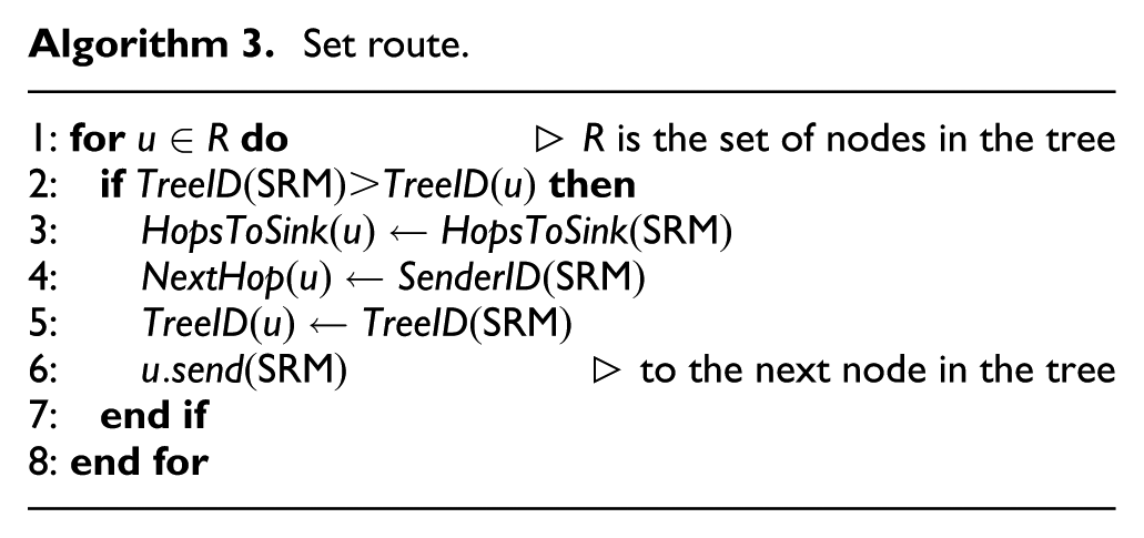
The SRM includes the tree ID parameter to handle multiple events. When a node receives an SRM, it validates if the tree ID of the SRM is greater than its tree ID, as shown in Line 2 of Algorithm 3. So, the parameters of the node are updated (Lines 3–5 of Algorithm 3) and the SRM is transmitted to the following node in the routing tree (Line 6 of Algorithm 3).
Data transmission
The sink is in charge of computing improved routing trees; therefore, when the sink finds a better solution than the current one, the sink sends an SRM to the network. This is a key characteristic of the proposed algorithm and is the reason why it is called ICER.
Meanwhile, more than one event can be detected, so it may be possible that some RRMs are received at the sink while it is still processing the previous request. When an RRM arrives at the sink, the computing process at the sink is reset including the new node that requested the route.
In addition, it is also possible that an SRM traveling in the network overrides a configuration on a node that has already been configured with a better route. To handle this situation, the nodes store the routing tree ID, and the SRM has the new tree ID it is aiming to set. Then, a node will only overwrite its routing table if the SRM’s tree ID is greater than the one recorded on the node, which can be seen in Line 2 of Algorithm 3.
These three characteristics allow the routes to be changed according to the needs of the network, always improving the routing tree; hence, the routing trees generated by ICER are dynamic. Furthermore, the data collection is independent of the routing configuration; therefore, the relay nodes always retransmit the data packets using the last configured routing tree. The data packets contain a field for the used energy of the node; then, when they reach the sink, it knows the state of the battery usage of the nodes.
Event ending
When an event ends, the routing infrastructure no longer needs to consider the nodes that reported such event. In fact, maintaining that same routing tree affects the overall performance of the network. For that reason, when a node finishes reporting an event, it sends a Remove Message (RM) to the sink using the existing routing tree. Upon receiving the RM, the sink resets the algorithm by taking off the node that sent the message. Then, the sink proceeds as usual, that is, it reconfigures the network each time an improved routing tree is found.
Battery usage and depletion
Eventually, after a certain time of the network activity, the batteries of the nodes start to deplete. The battery is discretized into a number of levels of the total battery capacity. Thus, a node starts functioning on the first level of the battery, and each time a node reaches the following level, it sends an RRM to the sink to reconfigure the network; this is done in order to homogenize the battery consumption between many nodes. When the last level is reached by a node, it sends a Dead Node Message (DNM) to the sink in order to report it as dead. In the reception of the message by the sink, it removes the dead node from the network, executes the centralized algorithm and reconfigures the network. The reason why a threshold is set for the node to be marked as dead is to avoid loss of packages; that is, due to the time the network needs to get reconfigured. There may be packets being transferred through the old routing tree in the meantime. Thus, the node’s battery cannot be depleted to complete those transmissions.
In addition to marking the node as dead, the neighbor nodes that have their next node parameter pointing to the dead node have to be reconfigured; otherwise, there would be a loss of packages. The dead node broadcasts a message to its neighbors in order to know which of them are in the described situation, and it includes the list of nodes that have to be reconfigured in the DNM. Then, when the sink reconfigures the network, it also includes the list of reported nodes by the DNM.
Centralized algorithm
The centralized algorithm is composed of three parts: the preprocessing which is executed to reduce the size of the instance; a heuristic which is used to find an initial solution and to prevent the generation of too much overhead; and the GA which continuously finds improved solutions.
As stated in the previous sections, an aggregation tree is equivalent to a Steiner tree. Each time a node senses a new event, it requests a route to the sink; consequently, a new instance of the Steiner tree has to be solved and returned to the network. This also happens when an event ends and when a node changes its level of energy. Therefore, the problem has to be solved several times to compute new routing trees each time any of the mentioned situations occur. When a request for a new routing tree reaches the sink, it knows, due to the configuration phase, the structure of the network, which is represented as a graph
Let us recall that in the Steiner tree problem is given a graph
Each node in the network is represented by a vertex in

where
It is not necessary for the balance factor to be the same in different executions, which gives the application more control over the algorithm. Applications that need small delivery times could maintain the balance factor in a range of small values, while applications that need greater lifetimes could have the factor in a range of greater values.
Preprocessing
The size of the network can be defined in terms of the number of nodes and the number of links between them; when working with the network, the nodes are mapped as vertices and the links between them as the edges incident to the vertices. If the size of the instance can be reduced, by either eliminating vertices or edges, then the search space of the solution is also reduced. As the search space is reduced, the algorithms are potentially faster for finding a solution. This procedure has to be done carefully because when removing a vertex or an edge, an optimal solution could be lost. Consequently, these reductions have to ensure that at least one optimal solution is maintained. More formally, when a set of reductions
A node with degree one that is not a terminal can be safely deleted.
A node
An adjacent node to a terminal of degree one can be contracted into the latter.
All of them are referred to as degree test (DT). These reductions are shown to be useful when the network is sparse. Contrary, when the network is dense, they have little impact. Nonetheless, the computational cost of applying these reductions is small enough to be executed regardless of the network density. Note that the reduced instance may have fewer edges and vertices than the original, but actually the nodes in the network are not dead; therefore, when the solution is returned to the network, the vertices and the edges are mapped back to the nodes and connections they initially represented.
Repetitive shortest path heuristic
The repetitive shortest path heuristic (RSPH) is also broadly used in the context of Steiner tree problems. It was introduced by Takahashi and Matsuyama 23 and later improved by de Aragão and Werneck 24 and Polzin. 25 RSPH is implemented with a small variant based on the Fredman and Tarjan’s 26 version of the Dijkstra’s algorithm.
The heuristic receives a terminal
In addition, when two nodes are at the same distance, the tie is broken by the remaining energy on them, that is, the priority queue returns the node with more energy available first. This procedure is denominated node-weighted RSPH (NWRSPH).
The described procedure is executed for each terminal
Algorithm 4 presents RSPH. The loop in Line 2 is for computing a solution for each terminal, which is kept in the variable

The complexity of the Dijkstra’s algorithm based on Fibonacci heap is
BRKGA
A genetic algorithm (GA) is a metaheuristic inspired by the evolution mechanism and used for optimization problems. A feasible solution is a solution that complies with all the restrictions of an optimization problem. In a GA, a chromosome encodes a feasible solution. A chromosome is modeled as an array of numbers or a string. Each element of the chromosome receives the name of allele. The fitness value of a chromosome is the value of the objective function of the solution the chromosome represents. The decoder is the function that associates a chromosome with a solution and computes its fitness value. A set of chromosomes is called a population.
A GA starts by generating a random population, then evolves it generating a new one. The new generation is the result of combining and mutating the chromosomes of the previous one. The combination or crossover of two chromosomes can be done, for instance, by randomly selecting an index, then taking the alleles from the first chromosome before the index and the alleles from the second chromosome after the index resulting in a new chromosome. The mutation may be done by randomly changing some elements of the chromosome. The algorithm must be aware that when combining two chromosomes, the new chromosome might not represent a feasible solution; therefore, special care must be taken at this step.
Bean
27
proposed the Random-Key Genetic Algorithm (RKGA) which takes a uniformly distributed random number in the range of
Gonçalves and Resende 28 introduced the BRKGA. BRKGA ranks the chromosomes in a generation and selects the subset of chromosomes with the best fitness, which is called the elite set. Then, in order to combine two chromosomes, it chooses one chromosome from the elite set and the other one from the remaining chromosomes. In contrast with a normal GA, BRKGA introduces mutants as a set of random chromosomes instead of performing mutations.
The initial population is a random set of
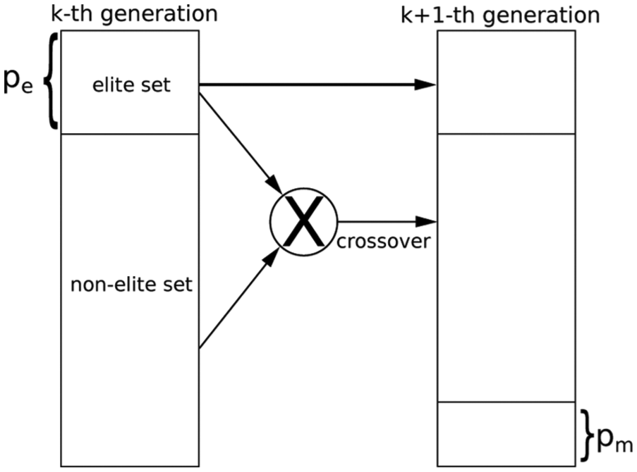
The BRKGA generates a new generation by directly copying the
The algorithm finishes after a given number of generations or when the reached solution is not significantly improved after a while. Since each chromosome is independent, the calculation to obtain its fitness value can be performed in a parallelized fashion. The used API 29 is able to define the number of threads for parallel decoding. Furthermore, the API offers the advantage of setting a number of independent populations which provides a broader search.
The parameters used in the algorithm are shown in Table 2. Solutions computed by NWRSPH are sorted by their objective value; the best K solutions are selected, codified, and introduced to one of the populations.
BRKGA parameter settings.

BRKGA: biased random-key genetic algorithm.
Decoder
The decoder receives a chromosome as an input and returns its fitness value. Each chromosome is an array of

The overall idea of Algorithm 6 is to traverse all the paths starting from

When the first event occurs, the solution is the shortest path between the sink and the terminal node; when subsequent terminal nodes request a routing tree, either because a new event appeared or because it also perceived the same event, the sink calculates the shortest path between the requesting node and the existing routing tree and executes the NWRSPH; thereupon, the solutions are codified into chromosomes that are inserted in the first generation of the BRKGA. Therefore, the initial solution found by BRKGA is not much worse than the current solution; hence, generating fewer set messages and making BRKGA converge faster.
At the notification of an event ending, the BRKGA removes the notifying node from the set of terminal nodes. The pruning will erase the unneeded nodes from the solution.
The reason why BRKGA is chosen, as mentioned above, is it allows parallel decoding, taking advantage of today’s hardware. In addition, the algorithm will always keep improving the routing tree until it eventually reaches the optimal tree. Finally, as noted in a previous section, the BRKGA could be replaced by any other heuristic that continuously feeds the network with improved routing trees.
To sum up this section, an example is presented in Figure 4 showing a series of pictures illustrating how the proposed algorithm works; the source nodes and the sink are represented as squares and the Steiner nodes are represented as circles. In addition, aggregation nodes have a darker tone.

ICER keeps improving the routing tree for the current source nodes; then, when the sink computes a better routing tree, the nodes belonging to the newly improved routing tree are reconfigured, setting a new route. The square nodes with an outgoing arrow are the source nodes, the square node with an ingoing arrow is the sink, and the connected nodes are part of the routing tree. (a) Only two source nodes gather data; (b) despite having the same number of edges as the previous image, some Steiner nodes are different, balancing the consumed energy; (c) when a new event takes place, a new source node starts delivering data; (d) ICER will keep searching for improved solutions, configuring the network each time the sink finds a new solution; (e) when a source node stops reporting data, it is discarded from the routing tree; and (f) ICER continuously keeps improving the routing tree.
Consider that there are two source nodes, as in Figure 4(a). ICER keeps searching for an improved routing tree. When one is found, as in Figure 4(b), the network is configured accordingly. Note that there is no difference in the number of edges between these two figures, but after some time of network operation, the nodes in the routing tree will diminish its battery level. Hence, nodes with more energy available become candidates to replace the previous ones; therefore, the value of the objective function, defined in 1, of the first solution is now greater than the objective of the second solution; therefore, it is replaced.
After that, consider the occurrence of a new event which is reported by the leftmost bottom source node; the routing tree now has two aggregation nodes, as in Figure 4(c). In an analogous way as in the previous case, ICER improves the routing tree again and configures an improved routing tree into the network, as presented in Figure 4(d).
Then, consider the disappearance of the event reported by the rightmost top source node and the appearance of a new event, as in Figure 4(e). Once again, ICER improves the solution considering only the source nodes that report data and changes Steiner nodes as needed, as in Figure 4(f).
Performance evaluation
ICER is compared with SPT, 6 DAARP, 8 DDAARP, 9 HCCRFD, 11 and CER. 15 The algorithm is evaluated using the simulator SinalGo version v.0.75.3. 31
In all the results, curves represent 95% confidence intervals for 33 different instances. Table 3 shows the scenario parameters used in the simulation. According to the metric, some parameters will vary as described in each section. The first event starts at time 2.000 s and the following events start at a uniformly distributed random time between
General parameters used for the simulation.

The following metrics were used for the evaluation:
Overhead: this is the number of packets needed to set up the routing tree. These include the packets used in the configuration phase and the packets used at request/set phase.
Tree size: this is the number of edges in the routing tree.
Dead nodes: this is the evolution over time of the percentage of nodes that do not have more energy to keep working at a given time.
Connectivity: this is the evolution over time of the percentage of nodes that do not have connectivity with the sink at a given time.
Network lifetime
Figure 5 shows the network lifetime for 1024 nodes and six events. It can be seen that the present algorithm extends the lifetime by a large amount. The fact that the algorithm continuously changes the routing tree avoids stressing a node, having a more homogeneous distribution of the energy use.

Percentage of dead nodes versus time (in s).
Different scenarios were used to test ICER. In general, the difference of the dead nodes is reduced when the network is sparse; hence, reducing the number of options that each node has to route the packets. For Figure 5, the average degree of nodes is 36, but for Figure 6, the scenario was changed so that the average degree is 9. For instance, at the end of the simulation, BA-ICER has only about 4.3% of dead nodes; while ICER has 5.1% of dead nodes, and CER has 6.1%.

Percentage of dead nodes versus time (in s) for a sparse network.
Figure 7 shows the percentage of connected nodes for the same previous scenario (with degree nine). In general, in a dense graph, a dead node will not disconnect other nodes, besides itself, from the sink; however, in a sparse graph, it is more likely that the death of a node disconnects other nodes since there are fewer nodes to route the packets.

Connectivity of the network over time for different algorithms.
For all cases, BA-ICER presents the most extended network lifetime, in terms of connected nodes, as well as alive nodes, despite having a bit more overhead than ICER and bigger tree sizes.
Overhead and tree size
Figures 8 and 9 show the size of the routing trees and the overhead, respectively, used by different algorithms.

Size of the tree expressed as the number of nodes in the routing tree.

Control packets generated by each algorithm.
Figures 8 and 9 are directly connected to the fact that ICER uses the NWRSPH, in contrast to CER which directly calls the BRKGA. The use of NWRSPH has two implications: it sets a good starting point by finding routing trees of good quality and, as a consequence, fewer routing trees are computed later by the BRKGA.
Figure 8 reflects the good quality of the routing trees, on which ICER has the smallest tree size. Note that BA-ICER is better than other approaches, but has tree sizes greater than ICER. This happens because BA-ICER tries to save energy possibly using larger trees.
Figure 9 reflects the small number of control packets generated by ICER; which is only improved by SPT, since SPT only makes one configuration. The control packets generated by ICER and BA-ICER are due to their continuous reconfiguration of the network over time. Nevertheless, only nodes that are part of the routing tree are reconfigured, so the overhead is affordable.
Events starting time window
In this scenario, the window of time in which the events happen is varied; therefore, the starting time of the events is randomly distributed in a window of time that is represented by the x-axis; and the percentage of dead nodes is plotted accordingly, after 6 h of the network operation. Figure 10 presents percentages of dead nodes after 6 h of simulation versus the maximum time at which the events occur. For instance, when all the six events appear randomly distributed at most within 2 h (7200 s), the percentage of dead nodes, after 6 h of network operation is 5.7, 7.7, 8.6, 15.2, 16.0, and 38.3 for BA-ICER, ICER, CER, DDAARP, DAARP, and SPT, respectively.

Maximum time (in s) at which all the events happen, randomly distributed within that window of time, versus the percentage of dead nodes after 6 h of simulation.
The observed behavior for all the algorithms, except for DDAARP, is an almost constant percentage of dead nodes without being affecting too much by the distribution of the events over time. The special behavior of DDAARP is because it completely changes the routing tree, if necessary, when a new event appears. Therefore, the more distributed over time the events are, the better energy balance is achieved.
However, SPT and DAARP have static routes, not changing them at all, saturating the nodes in the routing tree and depleting their batteries faster than ICER.
Conclusion and future work
The presented algorithm is based on an optimal aggregated-tree which is equivalent to the Steiner tree problem; then, the battery usage is introduced by assigning costs to the nodes of the network according to the spent battery.
The sink continuously computes improved trees and reconfigures the network. In addition, when some situations occur, such as the appearance of a new event, a significant change in the battery of a node in the routing tree, and the disappearance of an event, the algorithm is reset and a new routing tree is computed.
The main advantage of ICER is the flexibility introduced by the balance factor which can be changed throughout the execution in order to tune the routing tree according to the application requirements.
The comparison with other algorithms in the literature is promising, and even further reductions and improvements in the heuristics can be made. Other extensions of this work may include nodes with mobility, more complex models of energy, and configurations with hierarchical networks.
In this work, it has been considered that there is no packet fragmentation at all. Therefore, it is necessary that the packet be large enough to contain all the information needed to carry the connections of the network, at the configuration phase, and the configured routing tree, at the set route phase. Thus, there is a natural limitation when scaling the network given by the length of the packet. In none of our tests, which included networks up to 2048 randomly deployed nodes, fragmentation was needed. However, specially crafted layouts may reduce the size of the network. In a real scenario, links are usually unreliable. This situation could be handled by assigning a probability to the edges that represent the links. Other techniques such as duty-cycle could also be considered to extend the network lifetime. It remains as future work the inclusion of this kind of techniques into ICER.
Footnotes
Handling Editor: Xiaojun Zhu
Declaration of conflicting interests
The author(s) declared no potential conflicts of interest with respect to the research, authorship, and/or publication of this article.
Funding
The author(s) disclosed receipt of the following financial support for the research, authorship, and/or publication of this article: This work was supported by the National Council for Scientific and Technological Development (CNPq) grant nos 311499/2014-7, 425340/2016-3, and 308689/2017-8; and the São Paulo Research Foundation (FAPESP) grant nos 2013/21744-8, 2015/11937-9, and 2016/01860-1.