
Abstract
This article aims to optimize the information rate of a cognitive radio network with multiple secondary users. A primary user rate optimization approach based on dichotomy of the degree of freedom is proposed, where the primary users’ eigenmodes are adjusted according to its rate requirement. In order to provide a higher sum rate of secondary users, two interference alignment schemes are presented. The first one is an interference sub-space alignment scheme, which aims to align the sub-spaces spanned by interference from other secondary users with the sub-space spanned by interference from primary user. However, interference sub-space alignment may not be favorable in low signal-to-interference ratio region due to the negligence of the influence of noise. Thus, an iterative interference alignment scheme which maximizes the secondary system sum rate based on Grassmann manifold is developed. To accelerate the convergence speed, the objective function in Grassmann manifold is transformed into two parts without the inversion operation using the extensions of the Minkowski inequality. Simulation results show that interference sub-space alignment is more effective than Grassmann manifold to mitigate interference in the system with more secondary users. We further validate the effectiveness of Grassmann manifold and interference sub-space alignment in comparison with the existing schemes employing a water filling algorithm.
Keywords
Introduction
With the rapidly increasing data rate requirements of mobile users on multimedia applications, the accessible radio spectrum is becoming critically scarce. To address this issue, the cognitive radio (CR) concept was introduced to improve spectral efficiency in wireless systems.1–5 CR allows secondary users (SUs or cognitive users) to share the spectrum with the primary users (PUs or noncognitive users) under the condition that there is no or limited interference from SUs to the PU receiver. It has been a challenging problem to improve the performance of SUs while guarantee the minimum rate requirement of PU in CR networks. Effective interference management scheme called interference alignment (IA) was proposed in Cadambe and Jafar. 6
The main idea of IA is to mitigate the interference by dividing the received signal space into two sub-spaces, one for desired signals and one for interfering signals. At the initial research stage, IA schemes were presented in the closed-form expressions in the literature.6–9 However, these closed-form solutions were only achieved under certain conditions. As an alternative, iterative methods were developed to numerically solve the alignment problem.10–15 In Gomadam et al., 10 an iterative algorithm called interference leakage minimization was proposed for the multiple-input, multiple-output (MIMO) interference channel, which aimed to minimize the sum of interference powers at each receiver. This algorithm was extended to MIMO cellular networks in Zhuang et al. 11 According to Jafar, 13 the degree of freedom (DoF) was formulated based on a high signal-to-noise ratio (SNR) approximation. The authors proposed a rank-constrained rank minimization (RCRM) in Papailiopoulos and Dimakis, 14 which minimized the nuclear norm of the interfering space with a full rank constraint on the desired signal space. A weighted version of nuclear norm minimization for finding the optimal encoders was further presented in Sridharan and Yu. 15 Apart from the above schemes, the literature 16 analyzed the achievable DoF over space, time, and frequency. An IA scheme was proposed in Vahdani and Falahati, 17 which attained higher multiplexing gain using a lot lower number of channel extension.
Due to the signal separation between the interference and the desired information in multi-user interference channel, the IA scheme has been exploited in CR networks. Since the water filling algorithm (WFA) applied at a PU can leave some of its spatial dimensions unoccupied due to the power constraint, the secondary system reuses these eigenmodes for data transmission, as proposed in the literature.18,19 However, a PU using WFA might always spread its power among all its available eigenmodes at the moderate-to-high SNR regime, leaving insufficient eigenmodes for SUs at the moderate-to-high SNR regime and thus restricting SUs in the low SNR regime. Actually, SUs could still transmit data in the moderate-to-high SNR regime as long as the interference imposed by SUs on the PU was under the tolerance of PU. To this end, SUs in Cumanan et al.
20
optimized their transmit covariance matrix subject to an explicit PU rate constraints. Spatial shaping constraints considering the structure of interference was proposed by Lameiro et al.21,22 Under the assumption that the interference imposed by PU at each SU could be neglected, Lameiro et al.
21
extended the interference leakage minimization algorithm to incorporate the spatial interference shaping constraints. Lameiro et al.21,22 improved and presented a more general optimization framework to design the spatial shaping constraints. Guo et al.
23
proposed an eigenmodes constraint with which the number of eigenmodes used by the PU was adaptively adjusted by the rate requirement. However, Guo et al.
23
only studied the scenario where a MIMO PU shared its spectrum with one MIMO SU. In contrast to the above IA-based CR algorithms, a joint design of PU and SU was put forward in Men et al.,
24
where the CR system was considered as a
In this article, considering a system that a PU can coexist with multiple SUs, we propose a PU rate optimization approach based on dichotomy of DoF (DDA). As we have mentioned before, if the PU directly adopts WFA in the high SNR region, there would be less DoFs for the secondary system while the PU still transmits data with the maximum data rate. Considering that the PU just needs to meet the specific transmission rate or certain bit error rate to complete the communication process in some situation, the total DoFs of the CR network are obviously wasted. In order to solve this problem, this article presents the DDA algorithm in which the PU participates in part of the collaboration, leaving more DoFs for the secondary system. The secondary precoders in most IA schemes have been designed mainly to eliminate the interference from SUs to the PU. For any SU applying such an approach, the signals from other SUs cannot be aligned to the same sub-space. As a result, the interference among SUs can lead to poor performance of the secondary system. Taking this into consideration, this article employs a sub-matrix optimization method, where the precoding matrix is divided into two sub-matrices. The first sub-precoder eliminates the interference from SUs to the PU while the second sub-precoder alleviates the interference among SUs.
In order to suppress interference effectively, we propose an interference sub-space alignment (ISA) scheme to design the second sub-precoder. Different from the existing methods that minimizing the distances among the sub-spaces of different interfering signals, ISA aligns the sub-spaces spanned by interference from other SUs with the sub-space spanned by interference from PU and thus dispensed with the process of iteration. Although ISA can effectively mitigate the interference at each secondary receiver, it may not be favorable in the low SNR region due to the fact that the performance at low SNR is dominated by both interference and noise, whereas ISA ignores the influence of noise. To alleviate this drawback, this article proposes another approach for the secondary system, namely, secondary system sum rate maximization based on the Grassmann manifold (GSR). In GSR scheme, the second sub-matrices of precoders and decoders are designed to maximize the secondary system sum rate, and the optimization is introduced on GSR to obtain a faster convergence. However, if we directly take the sum rate as the cost function, then there exist plenty of inverse operations in the process of derivation. In order to reduce the complexity of GSR, we utilize the extensions of the Minkowski inequality to transform the sum rate formula into two parts without inversion operation. In some scenarios, the number of unused eigenmodes may not guarantee that there is at least one DoF obtained by each SU. To solve this problem, the proposed algorithms decrease the number of SUs and allow one or several “lucky” SUs to stay active for a long time whereas other SUs remain silent. Simulation results show that the achievable data rate of PU is higher than its minimum rate requirement by applying DDA. ISA is a more effective method in comparison with GSR for the system with more SUs. Numerical simulation results also validate the effectiveness of the GSR and ISA in comparison with the existed schemes employing WFA.
The rest of this article is organized as follows. Section “System model” introduces the system model. The details of the DDA scheme are described in section “DDA scheme for the PU.” Section “IA for secondary MIMO links” provides the ISA and GSR schemes for secondary MIMO links. Simulation results are given in section “Simulation results.” The article concludes in section “Conclusion.”
Notation
Throughout the article, we use bold uppercase and lowercase letters to denote matrices and vectors, respectively.
System model
Consider a
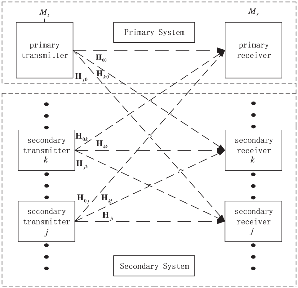
System model.
Symbols definition.

Assume that user k,

where
The received signal at the kth SU is expressed as

where

In our article, it is assumed that the secondary system has full CSI of the primary link, primary to secondary, secondary to primary, as well as the link between the secondary transmitter and receiver.
DDA scheme for the PU
Assuming that the interference generated by SUs to the PU is eliminated, which will be discussed later in section “IA for secondary MIMO links,” we choose

where
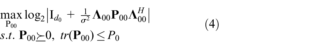
where

where
According to Vahdani and Falahati,
17
for a symmetric system with

From formula (5), PU may leave some of its spatial dimensions unused due to power limitations. Therefore, the unused spatial dimensions can be used by the secondary system operating in the same frequency band. However, with the increase in the SNR, there will be fewer or even none of the singular values left unused by the primary link. More specifically, if

Dichotomy of PU’s DoF.
Let
Condition 1: if
Condition 2: if
It is not difficult to find that
when
when
Note that when
As previously mentioned, after

The reconstructed channel matrix is

IA for secondary MIMO links
ISA scheme for the SU
Figure 3 shows the perfect IA, if the signals are constrained into the same sub-space at the unintended receivers, the desired signal can be recovered by eliminating the aligned interferences. However, as seen in Figure 4, not all the interfering signals can be aligned with

Perfect interference alignment.
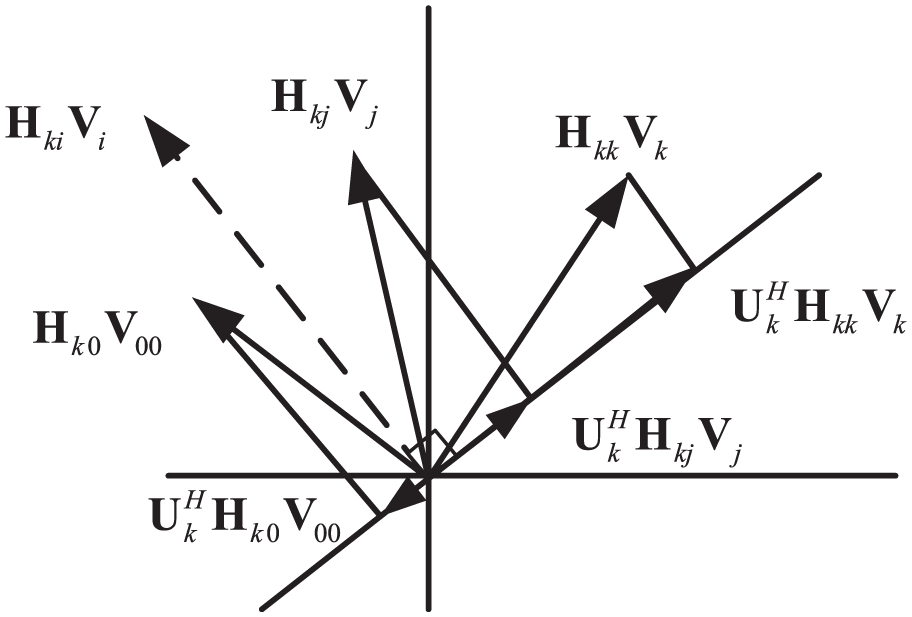
Practical interference alignment.
Precoding matrix design
It is assumed that SUs have accessed to the PU precoding and decoding matrices. In order to protect PU from the interference imposed by SUs, the secondary precoders need to satisfy

or equivalently

For a system with multiple SUs, it is very difficult to align the received interference signals that are processed by the precoding matrices in equation (9) into the same space direction. Taking this into consideration, this article employs the sub-matrix optimization method, where the precoding matrix is divided into two sub-matrices,
The first sub-precoder is designed to protect the PU from the interference imposed by SUs

The necessary condition for existence of solution for equation (10) is

The kth first sub-precoder is expressed as

where
To reduce the space dimensions occupied by the interference signals, ISA minimizes the sum of sub-space distances between different interfering signals over all receivers. Let

Theoretically, IA progressively reduces the sub-space distances between different interfering signals. However, since

It is not difficult to find that

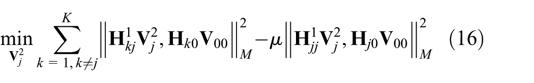
Thus, at each secondary transmitter, the optimization problem is

From the optimal solution, the majority of the interference experienced at the kth secondary receiver falls into the sub-space spanned by
According to Kumar and Xue,
28
the distance between two sub-spaces spanned by


Let


We further have


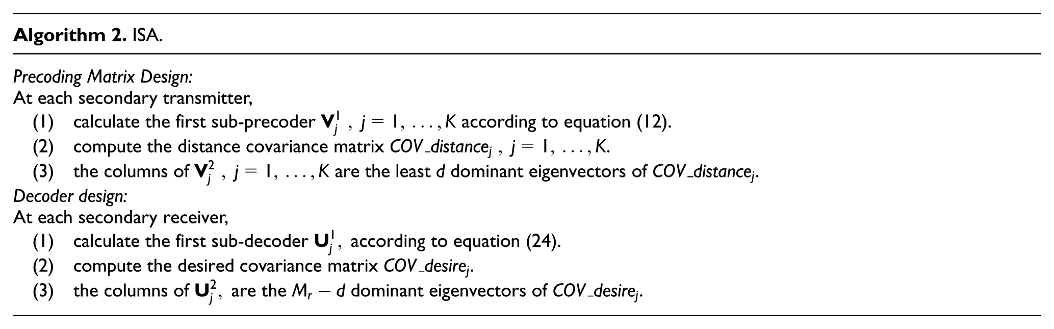
Decoder design
The decoder design also employs the sub-matrix optimization method, where the first sub-decoder is designed to eliminate interference, and the second sub-decoder is designed to improve the desired received signal power. In section “Precoding matrix design,” at each secondary receiver, the sub-spaces spanned by interference imposed by other SUs are almost aligned to the sub-space spanned by interference from PU. Thus, the first sub-decoder can be designed as the matrix spanning the null space of the matrix

Thus, the kth first sub-decoder is expressed as

where
To maximize the intended signal power, the columns in
SU GSR scheme
ISA only focuses on suppressing interference with noise neglected. In this sub-section, we propose an iterative scheme where the total secondary system sum rate is considered.
GSR also employs the sub-matrix optimization method, where the design of


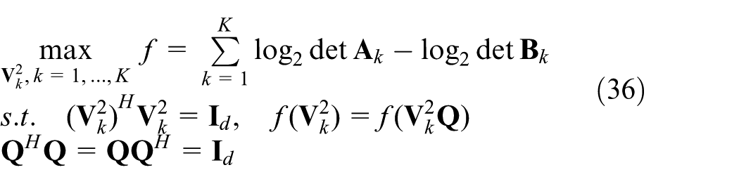
To improve the secondary system performance at all SNRs, one of the effective method is to maximize the system sum rate, as shown in equation (28)

For simplicity, we define

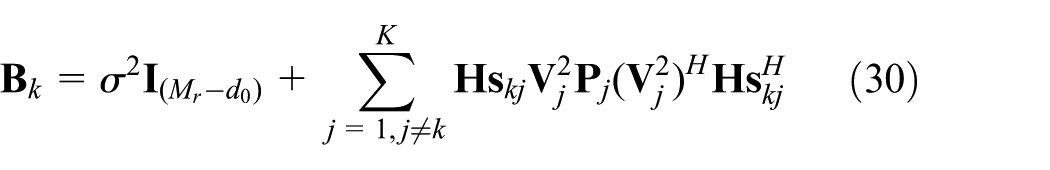
Thus

To solve the optimization problem in an iterative fashion, we first calculate the derivative of R in formula (31) with respect to

Appendix 1 shows the proof that formula (31) can be transformed into formula (32).
From

Intuitively, the steepest descent (SD) approach can be employed to search the local optimal point for
Traditional optimization schemes in the multi-dimensional space

In Manton, 29 the dimension of the schemes based on the GSR is shown to be

From equations (34) and (35), it can be clearly observed that the optimization on the GSR is effective in reducing the dimensions. Therefore a faster convergence can be achieved in the GSR scheme using GSR. Nevertheless, the objective function needs to be unitarily invariant in the precoders when GSR is used. Hence, we first need to prove that the objective function in formula (32) is unitarily invariant in
As a result, the objective function and the constraint can be simplified into
The tangent vector on the GSR is denoted as
Assuming the step size for each iteration is t, the iteration trajectory of the independent variable

where
where

The logical flow of the GSR algorithm is summarized as follows.

Remark
To guarantee that there is at least one eigenmode available to each SU, the DoF of PU needs to satisfy the following condition

However, the required DoF of PU to satisfy the minimum rate requirement could increase with the increase in the SNR. As a result, the unused eigenmodes are not enough for all the SUs. Thus, in this circumstance, we decrease the number of SUs which transmit concurrently with the PU. In order to allow more users to communicate at the same frequency band, we allocate 1 DoF to each SU. Therefore, according to equation (6), the permitted number of SUs is
Simulation results
In this section, we evaluate and compare the performance of ISA, GSR, OCIA,
17
SS,
22
ANEB,
23
PIA-SU,
24
and PIA-NSU.
24
Assume that one PU and K SUs coexist in the same frequency band. The DoFs of SUs are calculated according to equation (6). The system is represented by
The impact of
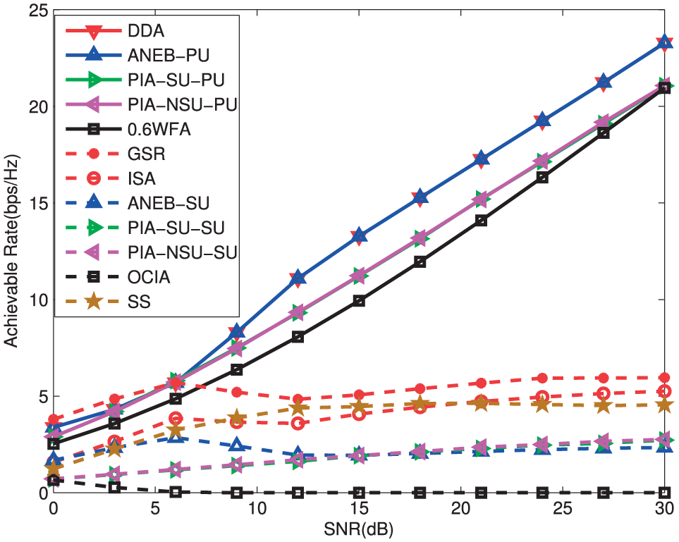
Achievable rate of the system versus SNR,
Achievable rate of the system versus SNR,
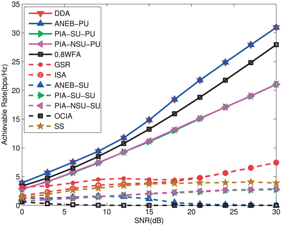
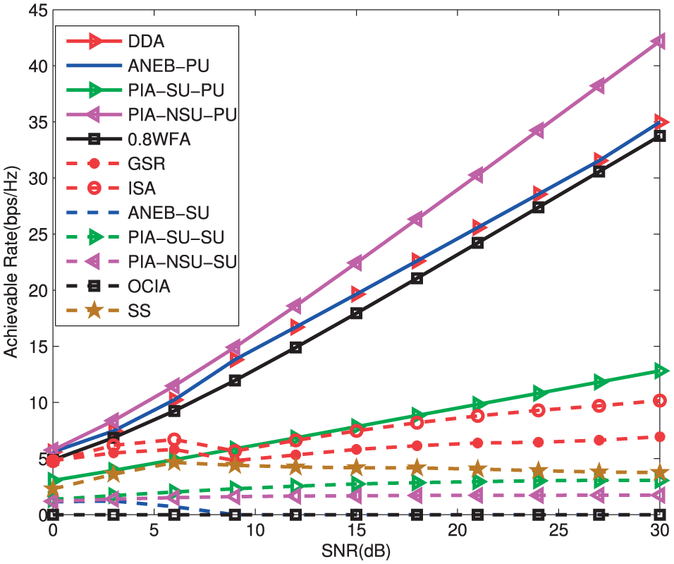
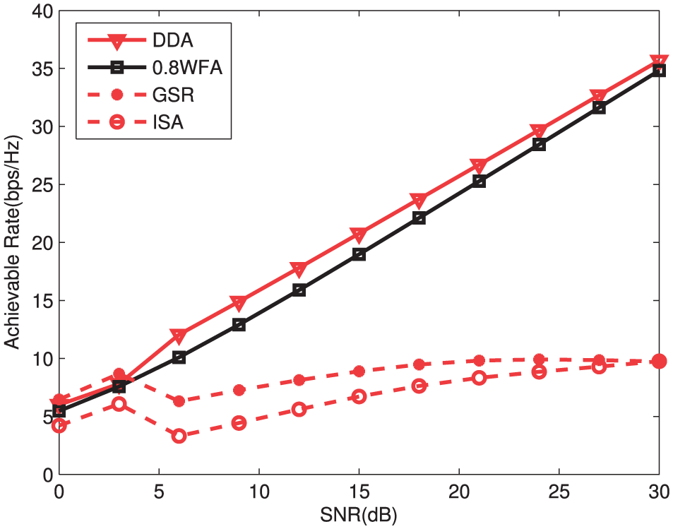
In Figure 5, GSR achieves the best secondary system performance compared with other six schemes. Under the same conditions, the transmission rate of SUs in the GSR scheme is about 2.7 bps/Hz higher than ANEB. For SNRs greater than 3 dB, the ISA scheme benefits from higher transmission rates compared with the ANEB approach. SS is superior to ISA for SNRs greater than 9 dB, whereas the ISA scheme performs better in the moderate-to-high SNR region. It can be seen in the figure that the achievable rate of SUs in GSR and ISA attains the maximum at 6 dB. It then keeps deceasing till SNR reaches 15 dB due to the fact that the obtained DoFs of secondary system reduce with the increase in the PU’s DoF. As we have known that the PU’s DoFs of ANEB and DDA have the same trend, correspondingly, the SU’s DoFs of ANEB and DDA have the same trend. Hence, the ANEB scheme also obtains its local maximum value at 6 dB. From Figure 5, it can be observed that the secondary system sum rate achieved by SS decreases for SNRs greater than 12 dB. The performance at moderate-to-high SNR region is mainly dominated by interference, whereas SS only addresses the optimization of a MIMO SU. As a result, the interference among SUs lead to poor performance of the secondary system when SNR gets higher. As shown in Figure 6, GSR can improve the performance of SUs significantly compared with other six algorithms for SNRs lower than 21 dB. Moreover, the transmission rate of SUs in the GSR scheme is about 3 bps/Hz higher than ANEB. With the increase in the SNR, GSR and ISA obtain their local maximum value at 12 dB and local minimum value at 18 dB. Different from Figure 5, for SNRs higher than 21 dB, higher achievable rates for the GSR and ISA schemes are achieved by the secondary links. Moreover, GSR and ISA present similar performance. On the contrary, the achievable rate of SUs in ANEB declines after SNR exceeds 21 dB, which shows that the ANEB scheme does not perform well when the total DoFs of the secondary system are less than K.
Figure 7 presents the achievable rates of PU and SUs when there are six transmit antennas, six receive antennas, two SUs, and

Achievable rate of the system versus SNR,
In Figure 8, the secondary system sum rate is plotted when the number of transmit antennas and the number of receive antennas are different. The performance of PU in the DDA and ANEB schemes are similar, both of which are greater than

Achievable rate of the system versus SNR,
Achievable rate of the system versus SNR,
The previous figures show that the secondary system achieves a superior performance by applying GSR. We further evaluate the computation complexity of GSR in Figure 10, in which the total achievable sum rate versus different iteration number is presented. A

Convergence of the GSR algorithm.
As mentioned earlier, the simulation curves of GSR and ISA are not monotonically increasing with SNR, the reason of which is explained through the analysis of K and

Achievable rate with one simulation,
Achievable rate with one simulation,
Achievable DoFs of PU versus SNR.

DoF: degree of freedom; PU: primary user; SNR: signal-to-noise ratio.
Number of “active” SUs.

SNR: signal-to-noise ratio.
Conclusion
In this article, we consider a cognitive network that comprises one primary link and multiple secondary links. We first propose a DDA scheme, which allows the PU to release some eigenmodes with the rate requirement still met. Although DDA achieves the same rate as ANEB, it benefits from a lower complexity compared with the ANEB approach, particularly in high SNR regions. To eliminate the received interference at each SU, this article proposes an ISA method, where the sub-spaces spanned by interference imposed by other SUs are constructed to cast overlapping shadows in the sub-space spanned by interference imposed by PU. Since ISA ignores the influence of noise, it may not work well at low SNRs. To tackle this problem, we further present an iterative algorithm to maximize the sum rate of SUs. Nevertheless, if we directly take the sum rate as the objective function, there will exist excessive inverse operations during derivation. Hence, in order to decrease the complexity of GSR, the objective function is transformed into two parts without inversion operation using the extensions of the Minkowski inequality. Besides, GSR is optimized to further improve the convergence speed of GSR. Simulation results show that DDA protects PU transmission while providing more unused eigenmodes for SUs. Simulations also indicate that ISA can be more effective than GSR to mitigate interference for the system with more SUs. When considering the physical layer aspects of the problem, the secondary links achieve higher data rates using GSR and ISA no matter whether the numbers of transmit/receive antennas are different or not.
Footnotes
Appendix 1
The following proves that formula (31) can be transformed into formula (32).
Appendix 2
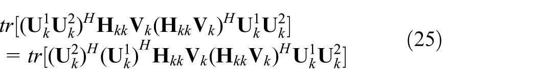
The following proves that the objective function in formula (32) is unitarily invariant in
Handling Editor: Donatella Darsena
Declaration of conflicting interests
The author(s) declared no potential conflicts of interest with respect to the research, authorship, and/or publication of this article.
Funding
The author(s) disclosed receipt of the following financial support for the research, authorship, and/or publication of this article: This paper was funded by the National Natural Science Foundation of China (grant no. 51509049), the National Key Research and Development Program (grant no. 2016YFF0102806), the Natural Science Foundation of Heilongjiang Province, China (grant no. F201345), and the Fundamental Research Funds for the Central Universities of China (grant no. GK2080260140).