
Abstract
Micro-electro-mechanical-system accelerometers and gyroscopes outputs are corrupted by significant random errors. The rotation modulation technique, which was mainly applied to ring laser gyro and fiber optical gyro, has been recently employed to compensate the micro-electro-mechanical-system inertial sensor errors in an inertial navigation system. As the fluctuating error processes in micro-electro-mechanical-system inertial sensors are difficult to be modeled or estimated, the inertial measurement unit rotating is an efficient way to automatically compensate for these random errors. This research applied the rotation modulation technique to the low-cost micro-electro-mechanical-system sensors and proposed an inertial system with rotating accelerometers and gyros for the land vehicle navigations. As previous research only studied the low-cost rotary inertial systems in the static conditions or simulation scenarios, the kinematic field tests are carried out to take the first look on the details and results of the low-cost rotary system for vehicular navigation. Accordingly, as the sensor random errors are very difficult to be dealt with, we conducted the analysis for the effect of inertial measurement unit rotation imposed on the random errors of the micro-electro-mechanical-system inertial sensors. Two different micro-electro-mechanical-system inertial measurement units are tested with a single-axis indexing table. The test results indicate the error mitigations are also related to the error characteristics of the inertial measurement unit as the navigation errors are more efficiently compensated for the micro-electro-mechanical-system inertial measurement unit that contains mainly the time-correlated noise than the one features significant white noise.
Keywords
Introduction
Integrated with the Global Navigation Satellite System (GNSS), the micro-electro-mechanical-systems (MEMS) accelerometers and gyros are extensively employed for the land vehicle navigations as they are small-size, low-cost, and low-power consumption.1–5 However, the time period that they bridge GNSS outages is very short as the MEMS inertial sensor outputs are corrupted with significant errors, which leads to dramatic navigation error accumulations. For example, the position errors of a low-cost MEMS-based inertial navigation system (INS) will grow to kilometers within several minutes.6–8 To compensate the INS navigation error accumulations, various investigations have been conducted. The artificial neural network (ANN) is applied to mimic the behavior of the navigation error accumulations of INS with training data; however, the error mitigation efficiency is limited when the training is insufficient.9,10 More precise and complexed models, such as auto-regressive (AR) model, are also used in the filtering for the inertial sensor errors. Although some improvements are observed on the estimation accuracy, the randomness of sensor errors still leads quick accumulations of navigation errors.11,12 Furthermore, other methods such as the non-holonomic constraints, adaptive filtering, are also proposed to limit the navigation error accumulations for the land vehicle navigations. However, these methods have their own limitations.13,14 Therefore, how to compensate the navigation error accumulations of a MEMS-based INS still needs further investigations.
The rotation modulation technique (RMT), which requires a rotation platform, has shown to be an efficient method to compensate the INS navigation errors by the rotations of the inertial measurement unit (IMU). For example, rotating the IMU with a constant angular rate can modulate the constant inertial bias into periodic signals, and an integration of the modulated inertial data over a complete rotation cycle can eliminate the bias impact on the navigation solutions.15,16 Geller first proposed the RMT in 1960s, which was later widely applied in the marine navigation for the submarines and warships.17–19 As the fiber optical gyro (FOG) and ring laser gyro (RLG) output the high-quality gyro data (the bias instability and noise level are very low), the application of RMT to those inertial sensors shows significant improvements on INS navigation solutions.15,16,20–23 In recent years, this technique was applied to the MEMS-based inertial systems to limit the navigation error accumulations. In Sun and colleagues,8,24 the simulations were used to verify the error compensations on constant biases. Furthermore, Du et al. 25 conducted the error analysis for the sensor constant biases, scale factors and installation errors with IMU rotation about X, Y, and Z axes, respectively, which was verified by the real rotated tests with a tri-axial rotation table in the lab environment. Previous researches have shown that the IMU rotations are able to modulate the errors in the MEMS inertial sensors and consequently reduce the navigation errors in the static case; however, the error compensation performance, as well as the ability to bridge the GNSS outages of the rotating IMU, must be investigated in real dynamic conditions for the land vehicle navigations. Moreover, although the reductions in the navigation errors were investigated from a macroscopic point of view, how the random errors are compensated through IMU rotations also requires investigations for the MEMS inertial sensors, which features significant random errors, such as time-correlated and white noise.
In this research, we proposed a MEMS-based inertial system with a rotating IMU based on the RMT for the land vehicle navigations. In such a system, the IMU is continuously rotating about the vertical axis of the body frame using a single-axis rotation table. As previous research only studied the low-cost rotary systems in the static conditions or simulation scenarios, the kinematic field tests are carried out to take the first look on the details and results of the low-cost rotary system for vehicular navigation. The Allan variance method is employed to study the effects of the IMU rotation imposed on the sensor random errors. The test results for two MEMS IMUs, namely, MTi-G and NAV440, are presented in this article, which indicate that (1) the IMU rotation improves the navigation performance of the MEMS-based inertial system that the horizontal position errors are reduced by about 2–3 times for the MTi-G and about 3–5 times for the NAV440 and (2) the navigation error compensations are more efficient for the MEMS IMU that mainly features time-correlated random errors.
Although the requirement for a rotational platform would increase the complexity and cost of the use of the RMT, it will be advantageous to attach the MEMS IMU to a rotating platform that is already built in the vehicle, such as the wheel for land vehicle, the airscrew for the helicopter, and the propeller for the boat, just to mention a few. In a recent research, gyros are attached to the wheel of a ground vehicle. In the near future, the advances in hardware technologies would also reduce the complexity and cost in developing rotational IMU devices, creating increased applications. In addition to the mitigation of navigation error accumulations in a non-aiding mode, the rotation of IMU will help improve the system observability as the observability of inertial sensor errors is related to IMU orientations. Overall, the rotary MEMS-based inertial system is expected to significantly improve the navigation performance comparing to a non-rotary one.
The remainder of this article is organized as follows. Section “MEMS-based INS with a rotating IMU” describes the inertial system with a rotating IMU, including the error mitigations, as well as the calibration algorithm. Section “Analysis of error compensations for sensor random errors” presents the Allan variance analysis for rotating and non-rotating inertial data. The conducted kinematic field tests and results analysis are given in section “Kinematic field tests and results analysis,” followed by the conclusions present in section “Conclusion.”
MEMS-based INS with a rotating IMU
As the IMU is rotating, the sensor frame or IMU frame in which the inertial readings are collected is introduced. Its axes are aligned with the sensitive axis of inertial sensors with the origin defined as the origin of IMU.8,24,25 For the inertial readings collected in the sensor frame, a transformation process is required before the mechanization algorithm, as shown in equation (1)

where
IMU rotations on MEMS IMU errors
The MEMS inertial sensors outputs are corrupted with significant random errors, which mainly consist of the random constants (usually referred as turn on biases), quantization noise, rate random walk, as well as the other long memory random process, such as 1/f noise.26–28 The scale factor and installation errors are also observed in the MEMS inertial sensors. As the gyro errors result much more significant navigation errors than the ones caused by accelerometer errors, the effect of IMU rotations on the aforementioned MEMS IMU errors are analyzed for the gyros as follows.
Random errors
As the IMU rotates about its Z axis with a rate of ω, the transformation matrix between the body frame and the sensor frame can be described by equation (2), and then, the sensor random constants in the body frame are modulated to periodic signals as shown in equation (3).24,25 Their integrations for a complete rotation cycle are zeros, which indicate that navigation errors caused by the modulated errors are eliminated. As the errors in the rotation axis cannot be modulated, the resulted attitude and velocity errors in vertical direction propagate in the same way as in the non-rotating IMU


where
As averaging the uncorrelated noise will decrease its variance, the integration process of the inertial system will decrease the variance of the quantization noise, which is white noise.8,26 If

where N is the total number of samples. According to Collin, 26 IMU rotation will reduce the variance of the time-correlated random noise, such as rate random walk and 1/f noise, though it cannot compensate for the white noise. Given the fact that the fluctuating error processes in MEMS inertial sensors are difficult to be modeled or estimated, the IMU rotating is an efficient way to automatically compensate for these random errors.
Scale factor and installation errors
MEMS inertial sensor scale factor usually varies as a function of surrounding environments (such as temperature),24,25 and it can be represented by the diagonal matrices in equation (5). Similarly, the installation errors are also temperature-dependent, 21 which can be described by equation (6)


where
IMU rotation induces additional gyro biases proportional to the rotation rate due to the scale factor of the Z axis, as shown in equation (7), and such bias results in the accumulated attitude errors after a complete rotation cycle as shown in equation (8). Moreover, the IMU rotation rate will be projected to the X and Y axes due to gyro installation errors and leads to additional gyro biases as shown in equation (9). Although those biases can be modulated, and the resulted attitude errors are removed after a complete rotation cycle, it still degrades the navigation solutions within the rotation cycle24,25

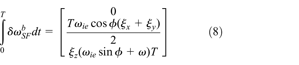


where
Calibration procedures
As the rotation-induced gyro biases lead to navigation errors, a calibration process is proposed to remove the gyro scale factor of Z axis,
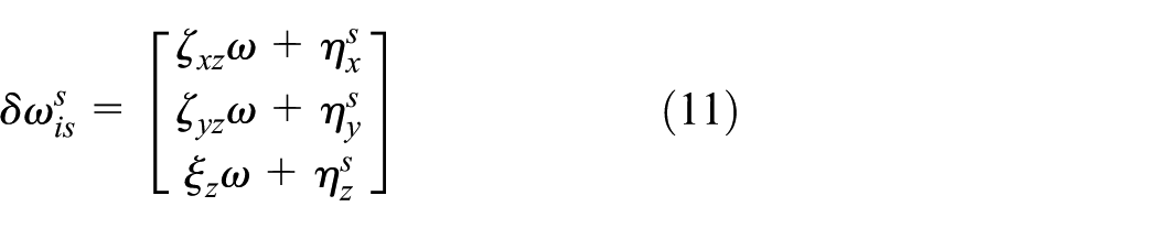
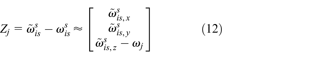

where
The calibration process contains two steps: (1) the tested IMU remains still on the rotation platform for 60 s and (2) the IMU rotates along with the rotation platform at a designated rotation rate about Z axis for 60 s. 25 As the MEMS IMU usually features significant non-linearity errors,29,30 the designated rotation rate in the calibration process should be the same as the one employed in rotation scheme. For example, for the MEMS-based INS with IMU rotation about Z axis at the rate of 10°/s, the calibration process should employ the same rotation rate to estimate the gyro scale factor and installation errors. The calibration errors by sensor noise can be calculated using equations (14) and (15). 31 Other error sources also include the gyro time–correlated random errors and the ignored earth rotation rate
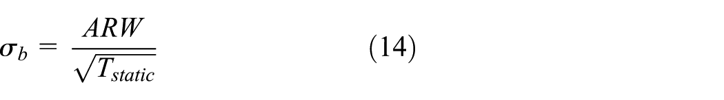

where ARW is the angular random walk of gyros,
Although the accelerometer errors also cause navigation errors, the gyro errors are the major factors of inertial navigation error accumulations, because (1) the gyro errors will cause the along-track and across-track position errors, whereas the accelerometer errors only cause along-track errors; (2) the gyro errors cause the cubic along-track errors, while the accelerometer errors cause quadratic errors.1,4,6 Therefore, this manuscript focused on the gyro error mitigations, and the analysis about accelerometer errors mitigations by IMU rotation can be found in previous studies.24,25
Analysis of error compensations for sensor random errors
The tool to analyze the effect of IMU rotation imposed on sensor random errors is the Allan variance, which is extensively employed to analyze the random signal characteristics in the time domain. The analysis procedures include two steps: (1) the Allan variance is calculated based on the inertial data collected in static mode to identify the major components of random errors for both IMUs and (2) the Allan variance of inertial data collected from a rotating IMU is also calculated and compared to the ones in (1) to investigate the sensor random error compensations. A single-axis indexing table is employed to rotate the IMUs as shown in Figure 1, along with its parameters given in Table 1. The MEMS IMUs, namely, MTi-G and NAV440, are tested in this section, and their specifications are given in Table 2.

Single-axis indexing table and IMU installations.
Technical parameters of single-axis rotation platform.

Specifications for tested IMUs.

The calculated log–log plots of the Allan variance for both IMUs are presented in Figure 2. The mean of the gyro data is removed to obtain the sensor random errors.11,28 The left and right figures show the Allan variance for MTi-G and NAV440, respectively. Obviously, the NAV440 outputs higher quality data as the Allan variance is much smaller than the ones for MTi-G. According to El-Sheimy et al., 28 the major components of random errors are quantization noise and bias instability for MTi-G, while the NAV440 features less noisy data but with much more significant rate random walk process.

Log–log plots of Allan variances for MTi-G and NAV440.
The log–log plot of the calculated Allan variance of the X axis of MTi-G is given in Figure 3 for both rotating and non-rotating cases, from which we can conclude that the variance of the correlated noise is reduced through the IMU rotation. To be more straightforward, the results of the Allan variance comparison between the rotating and non-rotating IMUs are present in Figures 4 and 5, for the MTi-G and NAV440, respectively. The IMU rotation rate is 10°/s. 25 By examining the variance of gyro data in the X and Y axes, we can see that the ones for NAV440 is greatly reduced by IMU rotations, as the major component of random errors is the rate random walk and other time-correlated signals, which can be efficiently compensated through rotations. However, the variance reduction on the MTi-G random errors is much less efficient, as they mostly consist of quantization noise. As the IMU rotation cannot modulate the errors in the rotation axis, the calculated variances in Z axis are most the same between the rotating and non-rotating cases for both IMUs.

Log–log plot of Allan variance of X gyro of MTi-G.

Allan variance comparison for MTi-G.

Allan variance comparison for NAV440.
Kinematic field tests and results analysis
As the dynamic conditions are usually much more complicated than static ones, the kinematic field tests are required to investigate the navigation error compensations by IMU rotations in dynamic conditions for the land vehicle navigations. This section presents the conducted kinematic field tests with both IMUs as well as its results analysis. In addition to the single-axis indexing table and two MEMS IMUs, the NovAtel SPAN system, which includes a high-end LCI IMU and a SE GNSS receiver, is employed to collect the data to generate the reference solutions. The equipment set-up on the test vehicle is shown in Figure 6. The indexing table with the installed MEMS IMU and the power supply are placed at the trunk of the vehicle, and the console, as well as the NovAtel SPAN system, is placed on the back seat row, with the antenna on the roof of the vehicle. The body frame of the MEMS IMU and the SPAN is aligned before the IMU rotations. The SPAN data, including both GNSS data and inertial data, are collected with the data rates of 1 and 100 Hz, respectively, and stored in the Secure Digital (SD) card of the GNSS receiver, while the MEMS IMU data and rotation angle data are collected by the indexing table console with the data rates of 100 and 50 Hz, respectively.

Equipment set-up on the test vehicle.
The designated trajectory for the kinematic field test includes straight lines, loops, and turns, as shown in Figure 7. Its total length is about 2.3 km. When the vehicle travels along the trajectory, it experiences accelerations and decelerations along west-to-east, north-to-south, and other different directions, as well as many velocity and azimuth variations. Consequently, the dynamic conditions of the kinematic test can represent the real scenario of the land vehicle.

Trajectory of kinematic field tests.
The kinematic field tests are conducted for both the rotating and non-rotating IMUs. For the non-rotating case, a single test is conducted for each IMU, in which the vehicle remains static for 5 min and then travels along the trajectory with the IMU remaining static relative to the vehicle during the entire test. According to Du et al., 25 the rotation rate is not the only factor that affects the error modulation for the low-cost MEMS IMU, which will also be affected by the sensor errors, such as the bias instability and the noise. Based on the conducted lab tests in Du et al., 25 the rotation rate is chosen as 10 and 20°/s for MTi-G and NAV440, respectively, for the rotating test. Six individual tests are conducted for each IMU. Each individual test started with a calibration process when the vehicle remains static, and then, the vehicle travels along the trajectory with the IMU rotating about the Z axis at the designated rate. The duration of the kinematic tests is about 210 s (not including the initial static period for the non-rotating test and the calibration time in the rotating test). The tests are conducted in an open sky environment and the reference solutions are generated by processing the SPAN data (including both GNSS and inertial data) using Waypoint Inertial Explorer from NovAtel, such that the reference solutions are accurate enough to evaluate the inertial solutions. With the initial position and attitude from the SPAN system, the non-rotating solutions are derived with the estimates of the gyro biases obtained by averaging the gyro data collected during the static period, 32 while the rotating solutions are derived with the gyro biases, scale factors, and installation errors from the calibration process. Then, solutions from both non-rotating and rotating tests are compared with the references to evaluate the navigation errors.
Kinematic test results with NAV440
By using NAV440, the obtained roll and pitch errors for the non-rotating test and the first individual rotating test are presented in Figure 8. The major error sources for the roll and pitch errors are the gyro random errors (gyro biases are already removed from the calibration). In the non-rotating case, the maximum roll and pitch errors almost reach 1°, and they varied dramatically due to vehicle dynamics. Through the modulation of gyro errors in the X and Y axes by IMU rotation, the roll and pitch errors are effectively reduced, compared to those errors in the non-rotating case. Additionally, they become oscillating signals with the period equals to IMU rotation period. Figure 9 presents the velocity errors in the east and north directions for the non-rotating test and the first rotating test. Similar to the attitude errors, the modulation of accelerometer biases and the reduced roll and pitch errors effectively dampen the error accumulation for the rotating IMU, and the oscillating behaviors are also observed with the same period.

Roll and pitch errors for non-rotating NAV440 and rotating NAV440.

Velocity errors in east-north plane for non-rotating NAV440 and rotating NAV440.
Figure 10 presents the calculated trajectories of the non-rotating test and the first rotating test, represented by the red and blue colors, respectively, as well as the reference represented by the green color. Although both the non-rotating and rotating solutions drift away from the reference without external aiding, the non-rotating one is completely diverged after tens of seconds, whereas the rotating one can still somewhat describe the shape of the traveled trajectory.

Trajectories for non-rotating NAV440 and rotating NAV440.
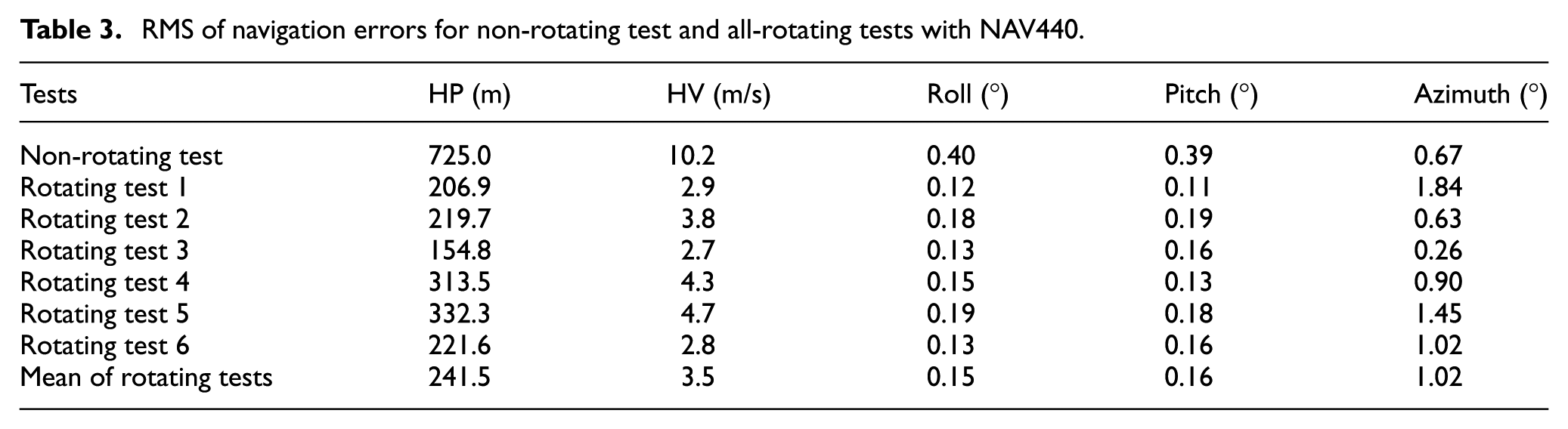
The root-mean-square (RMS) errors of the solutions for the non-rotating test and all rotating tests are summarized in Table 3. Through the IMU rotation, the horizontal position and velocity errors are reduced by about 3–5 times in the rotating tests compared to the ones in the non-rotating test. Although both the roll and pitch errors are significantly reduced with IMU rotation, the improvements on the azimuth solutions are nearly observed, as the gyro errors in the Z axis cannot be modulated.
RMS of navigation errors for non-rotating test and all-rotating tests with NAV440.
Kinematic test results with MTi-G
Figures 11–13 present the attitude errors, horizontal velocity errors, and the trajectories for the kinematic tests with MTi-G, respectively. Similar to the results of NAV440, the IMU rotation shows the ability to reduce the roll and pitch errors, as well as the horizontal position and velocity errors.

Roll and pitch errors for non-rotating MTi-G and rotating MTi-G.

Velocity errors in east-north plane for non-rotating MTi-G and rotating MTi-G.

Trajectories for non-rotating MTi-G and rotating MTi-G.
The RMS errors of navigation solutions from the non-rotating and rotating tests with MTi-G are calculated and summarized in Table 4. Greater navigation errors are obtained using MTi-G due to its greater sensor errors. Although sensor biases vary with time, the IMU rotations effectively reduce the position and velocity errors in the east-north plane, as well as the roll and pitch errors, such that the horizontal position errors are reduced by about 2–3 times in the rotating tests in comparison to the ones for the non-rotating test. Similarly, no obvious improvements are observed in azimuth solutions.
RMS of navigation errors for non-rotating test and all rotating tests with MTi-G.

Conclusion
The RMT has been recently applied to the low-cost MEMS IMUs, which has shown potential to compensate the navigation error accumulations of the inertial system and therefore to extend the time period it bridges the GNSS outages. Previous research studied the sensor error modulations and compensations by IMU rotations from a macroscopic point of view and conducted static tests in lab environments. To investigate the error mitigations by RMT under dynamic conditions for the low-cost system, this article conducted the kinematic field test with a land vehicle to take the first look of the navigation results. Accordingly, the effect of IMU rotation imposed on the sensor random errors are also analyzed using Allan variance method. Based on the analysis and tests results, we can conclude that (1) the IMU rotation can effectively compensate for the rate random walk and other time-correlated noise; however, it will not affect the quantization noise; (2) the IMU rotation about the vertical axis of the body frame can reduce the roll and pitch errors, as well as the horizontal position and velocity errors in kinematic environments; and (3) the error compensation performance is more efficient for the MEMS IMU that contains time-correlated random error than the one features significant white noise.
Footnotes
Handling Editor: Hassen Fourati
Declaration of conflicting interests
The author(s) declared no potential conflicts of interest with respect to the research, authorship, and/or publication of this article.
Funding
The author(s) disclosed receipt of the following financial support for the research, authorship, and/or publication of this article: This study is partly supported by Sichuan Province Science and Technology Project (grant no. 2016GZ0062) and National Natural Science Foundation of China (grant nos 41604025 and 41704029).