
Abstract
Noncommutativity error of a strapdown inertial navigation system (SINS) in an unmanned aerial vehicle's (UAV) vibration environment is analysed. The traditional analysis of noncommutativity errors is based on a coning motion model, which is inconsistent with a UAV's vibration environment. In this paper the UAV's vibration form is discussed and is modelled as a sinusoidal angular vibration and a random angular vibration. Then, SINS motion models under these two forms of vibration are built up and the formulas for the noncommutativity errors are derived separately. In addition, the effect of a multi-sample algorithm is explored, which is an effective method for compensating for noncommutativity errors in cases of coning motion. Finally, the UAV's vibration environment is simulated and it is indicated that the simulation results of the SINS's noncommutativity errors are consistent with theoretical analysis.
Keywords
1. Introduction
The navigation system supplies the necessary information for the control of UAVs. Recently, research into UAVs' navigation has intensified considerably thanks to the growth of civil and military interest in UAVs [1]. SINS is one of the most popular navigation methods for UAVs which can measure the vehicle's position, velocity and attitude without signal transmission to external equipment [2]. The inertial measurement unit (IMU), which consists of gyros and accelerometers, is an important component of the SINS and its errors can greatly affect navigational accuracy.
The vibration environment of UAVs is complex, influenced by the actuating unit and aerodynamic forces [3]. Since IMUs are directly installed on UAVs, they are sensitive to vehicle vibration [4]. Special support [5] or dampers [6] for the SINS are usually needed to reduce the influence on the IMU of vehicle vibration, but the IMU cannot be completely isolated from vibration by these means. Moreover, some vibration reduction methods cannot be applied to small UAVs due to the limitation on weight and size. The SINS is affected by vibration in two ways: on one hand, noise is brought to the gyros and accelerometers [7–8], leading to decreased IMU accuracy; on the other hand, noncommutativity errors are introduced due to the rotational noncommutativity theory of a rigid body [9] and the SINS solution accuracy is decreased.
The vehicle is usually modelled as having a coning motion in a traditional noncommutativity error analysis of the SINS [10]. In this condition, attitude error spreads over time and navigation accuracy is degraded significantly by noncommutativity errors. A multi-sample algorithm, which increases the sampling frequency of the IMU, has a good compensating effect for noncommutativity errors. Meanwhile, noncommutativity errors under a two-frequency coning motion [11] and a general coning motion [12] are studied, which are more normal than classical coning motion. However, the motion models above do not consider the characteristics of a UAV's vibration.
In this paper, the form of a UAV's vibration is analysed, and an analysis method of the SINS noncommutativity errors brought about by the UAV's vibration is proposed. In addition, the effect of the traditional algorithm applied to noncommutativity errors compensation is explored in the case of the UAV's vibration. First, the vibration environment of UAVs is discussed in Section II. It is pointed out that sinusoidal vibration and random vibration are the main vibration forms of UAVs. Then a noncommutativity error formula of a SINS under sinusoidal angular vibration is derived in Section III and the effect of a multi-sample algorithm is analysed. In Section IV the expression of a SINS's motion in a time-domain under random angular vibration is deduced from its power spectral density (PSD) and then the same research is done as in Section III. SINSs under sinusoidal vibration and random vibration are simulated in Section V and the simulation results verify the effectiveness of the proposed theory.
2. Vibration environment of UAVs
Engine noise and air disturbance are the main sources of UAVs' vibration [13]: engine noise characteristics are closely related to the engine type, which is depended on the UAV type and will be discussed in subsequent parts of this section; air disturbance is influenced by meteorological conditions outside the UAV, such as wind velocity and weather, which have strongly random characteristics and can be described by random vibration.
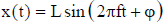
Electric motors [14] and piston engines [15] are usually used as actuating units in micro and small UAVs, which are mainly for short-distance reconnaissance. The vibration form of such types of UAV is close to sinusoidal vibration [15]. Sinusoidal vibration is periodic motion whose displacement changes over time in the form of a sine function. Vibration amplitude, vibration frequency and phase are denoted by L, f and φ respectively, and vibration displacement is given by:
Jet engines are usually found in medium and large UAVs [16] which are mainly used for long-distance reconnaissance or strikes. These UAVs' vibrations are caused by the jet engines' exhaust, and the vibration form differs from sinusoidal vibration and is described as random vibration [17]. Random vibration is expressed by its vibration PSD. Figure 1 shows an angular accelerometer PSD of an X-axis gyro in a SINS in a random vibration experiment. The PSD is drawn using gyro outputs and it is obvious that the PSD presents random characteristics under the experimental conditions. Limited to the sample frequency of gyros, the upper cut-off frequency of the PSD is only 50 Hz. However, the frequency bandwidth of real random vibration is usually wider and can be up to several thousand Hz.
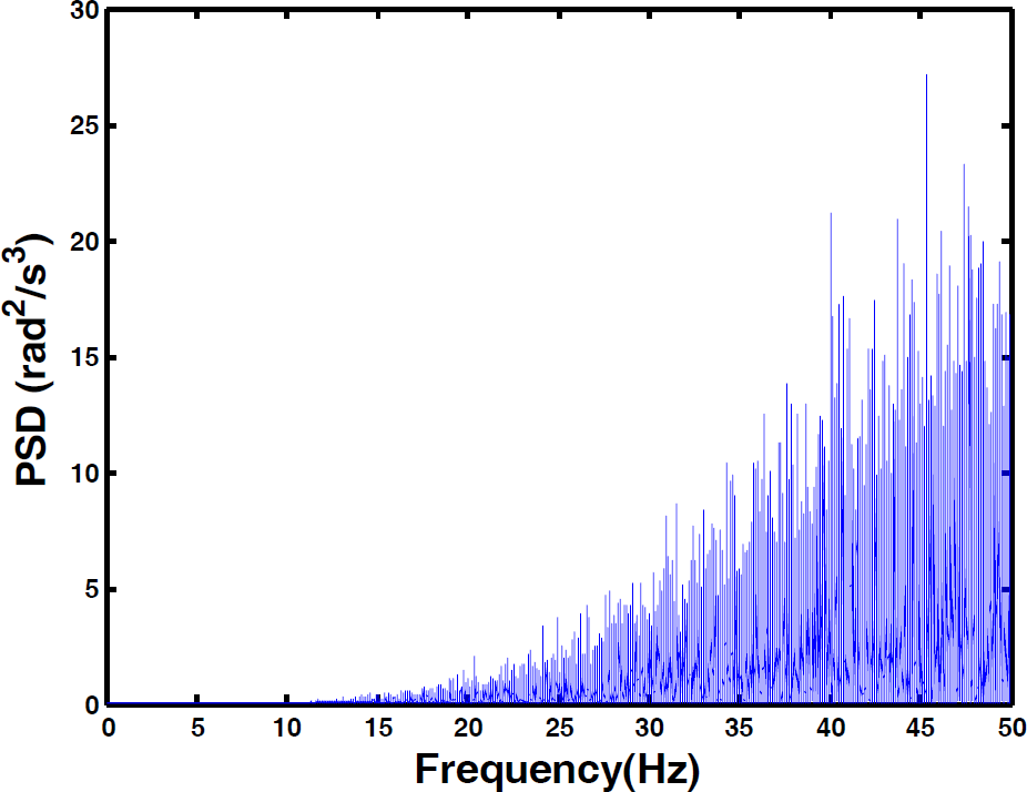
Angular accelerometer PSD of X-axis gyro of a SINS in a random vibration experiment
IMUs are installed on UAVs with supports. Due to the damping effects supplied by the supports vibration amplitudes are degraded when transmitted to the IMUs. However, the vibration forms of IMUs are almost the same as the UAVs' bodies. So sinusoidal vibration and random vibration are chosen to describe the IMUs' motion under the UAVs vibration. Since noncommutativity errors are introduced only by angular motion [18] the discussion in this paper is limited to angular vibration and the vibration considered is only one-degree-of-freedom for simplicity.
3. Noncommutativity errors of SINS under sinusoidal angular vibration
Sinusoidal vibration is the main vibration form for UAVs with electric motors or piston engines (such as Quadcopters and small unmanned helicopters). Noncommutativity error expression of the SINS is derived in this section and the effect of a multi-sample algorithm is explored.
3.1 Noncommutativity error expression
Body coordinate frame b is assumed to undergo sinusoidal vibration relative to reference coordinate frame r. Vibration amplitude and vibration frequency are denoted by L and ωs respectively and phase is assumed to be 0 without loss of generality. Since vibration is single-degree-of-freedom the unit directional vector is given by[sinαcosβ cosαcosβ sinβ], and the reference to the body quaternion of sinusoidal vibration can be written as:


and

where
According to the relation between the updated quaternion
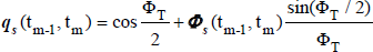
where ΦT =

then

It can be seen that all components of

where i = 1,2,…,N. In the above analysis Eq. (6) is the theoretical value of the rotation vector

It can be seen that all the components of the noncommutativity errors under a sinusoidal angular vibration are periodic, which do not accumulate over time, leading to small attitude errors. However, for coning motion only two components of the noncommutativity errors are periodic and one component has a constant value, which produces a drift rate error in the updated quaternion
3.2 Effect of the multi-sample algorithm
According to the multi-sample algorithm, gyros are sampled multiple-times per attitude update, and noncommutativity errors can be compensated by the cross products of the gyros' samples. However, from Eq. (9) we see that the cross products of the gyros' samples are all zeros. This means Δ
4. Noncommutativity errors of SINSs under random angular vibration
Random vibration is the main vibration form for UAVs with jet engines (such as high altitude long-endurance UAVs). In this section the motion model of an SINS is analysed, a noncommutativity error expression is derived and the effect of a multi-sample algorithm is explored.
4.1 SINS's motion modeling
Body coordinate frame b is assumed to do random vibration relative to reference coordinate frame r. The angular acceleration's discrete PSD is denoted as Sa (ω), sampling time is T, total time is nT, then the resolution of the PSD is Δf = 1/nT.
Since a SINS's motion model is related to angular displacement, it is required to transform the angular acceleration's PSD Sa (ω) to an angular PSD Sd (ω) by the following formula:

According to the PSD analysis theory the relation between the PSD and the frequency spectrum is known for limited data. Then the expression of random vibration in the time-domain can be written as:

where Li = √2ΔfSd (iΔf), ωi = 2πΔfi, φi is the phase corresponding to each frequency component. However, the PSD only contains the amplitude information of the signal and the phase is unknown, so the signal expression in the time-domain cannot be restored only by the PSD. Referring to the processing method in the vibration table [20], all phases are assumed to be an even distribution within [-π, π].
4.2 Noncommutativity error expression
The unit directional vector of random vibration is [sinαcosβ cosαcosβ sinβ] and the reference to body quaternion can be written as:


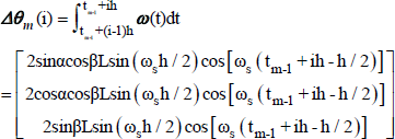
Assuming that N gyro samples are taken between tm-1 and tm, the gyro sampling time is h = T / N. Limited to the gyro bandwidth, high-frequency vibration cannot be sensed. If fb denotes the gyro bandwidth, fh denotes highest frequency of vibration, then the gyro samples Δθ


where j = 1,2,…,N, n' = fbn/fh. Eq. (14) is the theoretical value of the rotation vector Φ
Although every frequency component of the noncommutativity errors is periodic, the periodicity of the whole expression is unknown since all the phases are random values. This means that conclusions cannot be directly drawn from the analytical expression, but simulation analysis can be done using the above steps.
4.3 Effect of the multi-sample algorithm
Similar to sinusoidal vibration the cross products of the gyros' samples are also zeros according to Eq. (16). So it can be concluded that the multi-sample algorithm has no compensating effect for random angular vibration.
5. Simulation results and discussion
Sinusoidal angular vibration and random angular vibration for SINSs are simulated to verify the conclusions in this section. Noncommutativity errors and multi-sample algorithms are both discussed.
5.1 Simulation under sinusoidal angular vibration
Simulation conditions are set as follows: the sine vibration frequency is 20 Hz and the angular vibration amplitude is 2deg; α = 30deg, β = 60deg; total time is 1000s and the simulation step is 0.1s. Single-sample algorithms and four-sample algorithms are used for the SINS's attitude solution respectively. The noncommutativity errors are shown in Fig.2 and Fig.3. the SINS's attitude errors are shown in Fig.4.

The noncommutativity errors of the single-sample algorithm under sinusoidal angular vibration

The noncommutativity errors of the four-sample algorithm under sinusoidal angular vibration

Attitude errors under sinusoidal angular vibration
From Figure 2, it can be observed that all the components of noncommutativity errors are periodic and the amplitude differences are caused by the directional vector. By comparing Fig.2 and Fig. 3 it is found that the noncommutativity errors of the single-sample algorithm are equal to those of the four-sample algorithm, which means the four-sample algorithm has no compensating effect. Figure 4 shows the attitude errors under sinusoidal angular vibration, which are in the order ten to the negative seven arc seconds. These values are very small and can be omitted in practice. This is because the noncommutativity errors are periodic and the attitude errors do not accumulate over time.
5.2 Simulation under random angular vibration
Simulation conditions are set as follows: Figure 5 shows the angular acceleration PSD of a random vibration, which is between 15Hz and 2000Hz; α = 30deg, β = 60deg; total time is 1000s, and the simulation step is 0.1s. The noncommutativity errors of the single-sample algorithm and the four-sample algorithm are shown in Fig.6 and Fig.7. The SINS's attitude errors are shown in Fig.8.
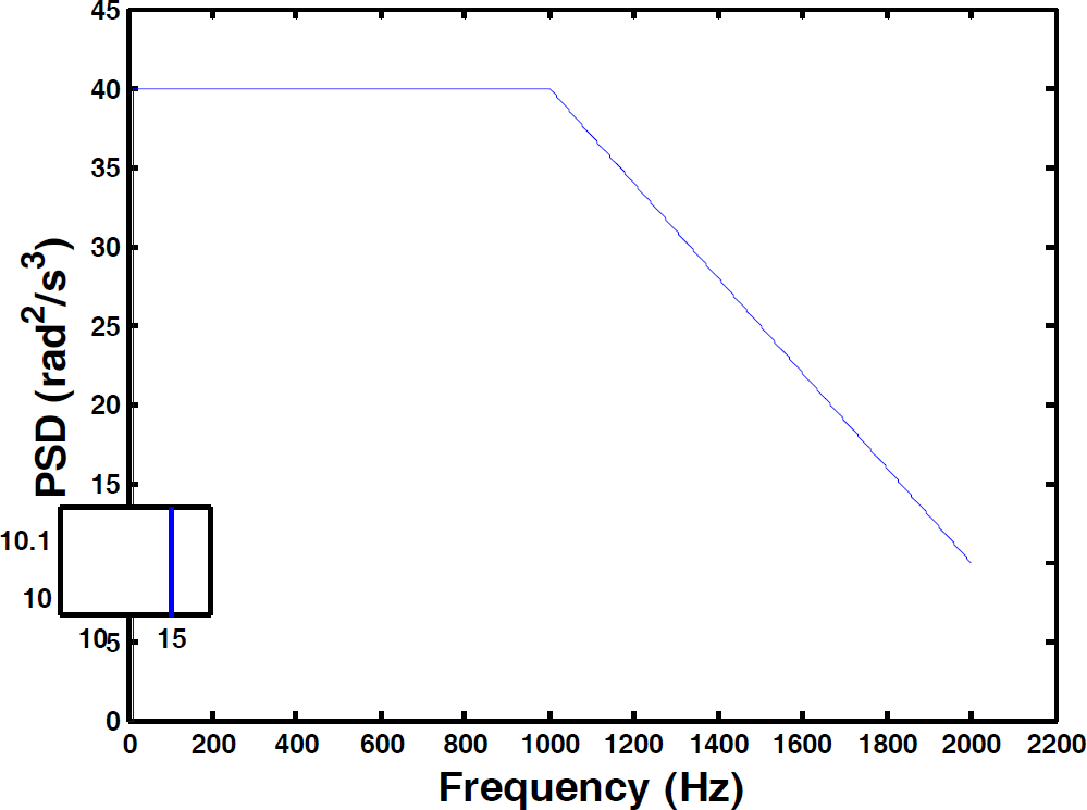
Angular acceleration PSD of random vibration
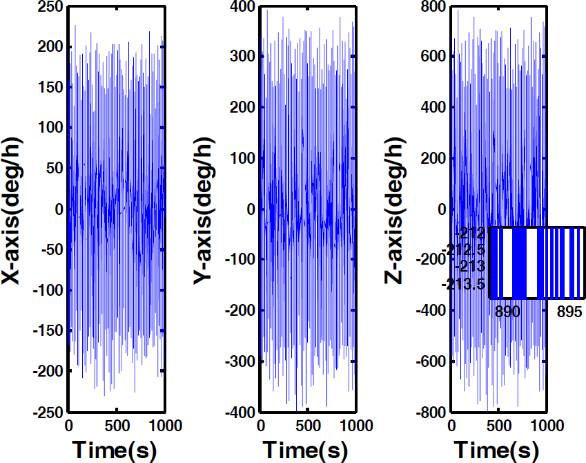
The noncommutativity errors of the single-sample algorithm under random angular vibration

The noncommutativity errors of the four-sample algorithm under random angular vibration

Attitude errors under random angular vibration
From Fig. 6 it is clear that all the components of the noncommutativity errors are random and without periodicity. By comparing Fig.6 and Fig. 7, it is found that the four-sample algorithm has no compensating effect for noncommutativity errors, which is similar to sinusoidal angular vibration. Figure 8 shows that attitude errors under random angular vibration are in the order ten arc seconds. Attitude errors present oscillation forms and are not divergent. The amplitudes of the attitude errors are relatively large and need to be considered during the SINS's navigation process.
6. Conclusions
SINS noncommutativity errors in a new motion form are analysed. This is partly based on a random motion model and it is a better description of UAV vibration than the traditional deterministic models. Through theoretical analysis and simulation we can draw the following conclusions:
Noncommutativity errors present periodically under single-degree-of-freedom sinusoidal angular vibration. Attitude errors are small and can be omitted in practice.
Attitude errors are influenced by both noncommutativity errors and gyros bandwidth under single-degree-of-freedom random angular vibration. Usually PSD is used to describe random vibration and doesn't contain phase information of the vibration. So a random vibration expression in a time-domain cannot be derived through PSD and noncommutativity errors cannot be found through theoretical analysis.
The multi-sample algorithm used in noncommutativity error compensation under coning motion is not suitable for single-degree-of-freedom sinusoidal angular vibration and random angular vibration.
Besides, a simulation method is proposed to analyse SINS noncommutativity errors under random angular vibration, whose principle and steps are presented. By setting the PSD of random angular vibration and the gyros' bandwidth, the noncommutativity errors and attitude errors can be analysed through simulation.
Footnotes
7. Acknowledgments
This work is supported by National Natural Science Foundation of China(91016019, 61174197), the Funding of Jiangsu Innovation Program for Graduate Education (CXLX11_0201) and the Funding for Outstanding Doctoral Dissertation in NUAA (BCXJ11–04).