
Abstract
Flying ad-hoc networks are becoming a promising solution for different application scenarios involving unmanned aerial vehicles, like urban surveillance or search and rescue missions. However, such networks present various and very specific communication issues. As a consequence, there are several research studies focused on analyzing their performance via simulation. Correctly modeling mobility is crucial in this context and although many mobility models are already available to reproduce the behavior of mobile nodes in an ad-hoc network, most of these models cannot be used to reliably simulate the motion of unmanned aerial vehicles. In this article, we list the existing mobility models and provide guidance to understand whether they could be actually adopted depending on the specific flying ad-hoc network application scenarios, while discussing their advantages and disadvantages.
Introduction
Many recent research works in the computer systems, electronic and communication topics have been focusing on unmanned aerial vehicles (UAVs), also called drones. The utilization of UAVs for all sorts of tasks is becoming popular, particularly for monitoring and surveillance applications. This is due to the rapid technological evolution allowing a fast and economic production of flying systems, which can fly autonomously or be remotely controlled by human personnel. The dynamic characteristics of flying devices allows the use in many different scenarios, such as military, 1 disaster or emergency management,2–5 and civilian applications.6,7
Recently, the deployment of a swarm of UAVs to pursue a task has become an interesting option to improve the efficacy of current single UAV systems. Using a group of UAVs, instead of deploying and operating a single UAV, offers many advantages, such as the possibility of extending the mission coverage, guaranteeing a reliable ad-hoc network, and improving the operation performance through multi-UAV cooperation. 8
The possibility to use a swarm of UAVs, which may collaborate with each other to offer a cooperative task, introduces important communication issues, also in terms of QoS. 9 UAVs need message transmissions among themselves (and toward the base station) to permit such a cooperation and, due to the high mobility levels of UAVs, routing becomes one of the most critical aspects in this context. 10 The maximum communication range is typically also limited, especially when smaller and lower-cost UAVs are used. The problem of achieving line-of-sight can, in some cases, be alleviated by increasing the altitude. However, this also requires greater communication ranges, and the airspace at higher altitudes may be restricted by aviation regulations. Smaller UAVs may also be unable to ascend to sufficient altitude to achieve line-of-sight to both the target and the base station.
To face these problems, many researches have proposed innovative communication protocols. These proposals employ simulations as a validation tool in order to analyze their performance metrics. The requirements for a simulator used in this context are a sound modeling of realistic UAV movements, dimensions and communications. Simulations that involve mobile nodes require a mobility model to represent how the nodes change their position while communicating, in order to analyze the network performance under mobility.11,12 When flying objects are considered, a mobility model specifically designed for UAVs is needed. Such models are not yet well explored, since many researches ground their simulations on simpler mobility models, like the Random Waypoint (RWP) model, which have actually been designed for traditional mobile ad-hoc networks (MANETs). Nevertheless, the mobility of flying devices is very different from ground vehicles or other devices, due to the aerodynamic constraints. Hence, these mobility models fail to accurately reproduce the realistic behavior of UAVs and could severely mislead the simulation outcome. 13
In this article, we categorize and describe real possible flying ad-hoc network (FANET) application scenarios and describe available mobility models for simulators, with particular reference to flying devices and related realistic motion. We aim to provide the requirements for each application scenario that involves a multi-UAV system, for example, the need for an always connected network. By modeling these requirements in terms of UAV movement and coordination specifications (type of movement, speed, direction, etc.), we are able to associate the most feasible mobility models for any scenario or to conclude that certain mobility models could not replicate particular realistic cases.
This article is structured as follows: section “Motivation of realistic mobility models” explains why realistic mobility models should be used in simulators for network analysis. Section “Application scenarios of FANETs” lists several application scenarios in which FANETs are involved. Section “Mobility models” provides a critical analysis of the state-of-the-art regarding mobility models. Section “Representativeness of existing mobility models” details the features of the different mobility models regarding their degree of realism. Section “Application scenarios and mobility models” associates FANET applications with the most adequate mobility model(s). Finally, section “Conclusion” concludes the paper.
Motivation of realistic mobility models
Generally, before simulating a network scenario, a communication model, the mobility pattern of nodes, and other parameters are set. In particular, the specific mobility model adopted by nodes can significantly affect the performance of a simulated aspect of the network, like routing performance.13,14 Many research works analyze protocol performance using very trivial mobility models, like the RWP or the Random Walk models. Nevertheless, in the context of UAV networks, they could not fully reproduce the actual behavior of UAVs. Consequently, network simulations might show incorrect results with respect to those that would be obtained under real conditions. For example, the performance of a particular routing protocol for a specific UAV application scenario can be poor when using the RWP mobility model, but it could be very good when using a mobility model specifically designed for that application scenario. When flying objects are considered, a realistic mobility model specifically designed for UAVs is needed to effectively highlight possible issues. A significant requirement to get a realistic UAV motion is to have smooth trajectories, due to the aerodynamic conditions. In Yao et al., 15 the authors propose a grid model for UAV path planning that also considers smooth curves. The work in Wang et al. 16 introduces several reasons to use realistic mobility models rather than simple random ones:
The mobility model is an important factor affecting the performance of a FANET, so it is important to establish a realistic movement pattern.
The distribution of node location impacts upon many network characteristics such as network connectivity, average path length, and network capacity.
Random patterns may be very different from actual movement patterns found in the real world, and the simulation results obtained based on these models exhibit obvious differences from more realistic scenarios.
Typically, the network connectivity varies because the distributions of node location and speed vary over the simulation time horizon. A non-uniform distribution reduces the applicability of existing analytical results, which are typically based on the uniformity assumption.
Finally, these models are almost always based on simple straight line patterns which differ from many real world scenarios. UAVs usually mimic the movement of flocks of birds, or shoals of fish. In this case, they should move along continuous, curved trajectories rather than in a simple straight line.
Application scenarios of FANETs
There are many application scenarios that can make use of a swarm of UAVs to perform any distributed task. Several UAVs have been developed with the capability to communicate with each other, so that they can collaborate for a specific purpose. The main motivation to use multiple UAVs is to obtain a potential performance increase in terms of task completion time, compared to a single UAV. Considering these aspects, such UAVs swarms fulfill the principles of a distributed processing system, 2 in which UAVs are the nodes of an entire system, which is managed through internal mechanisms and ad-hoc communication between nodes. In this section, we try to classify such applications in several categories, so as to obtain a general point of view of the different mobility models needed for each kind of application.
Search and rescue operations
In the search and rescue context, UAVs are looking/sensing for a target, typically on the ground. UAV networks were used for search and rescue missions for the first time during Hurricane Katrina in 2005, and later in the 2011 Fukushima disaster, and in the April 2015 Nepal earthquake. 17 In Ho et al., 5 a collaborative, multi-UAV system for disaster and recovery scenarios is proposed. The system is employed to asses unreachable areas for human personel, detecting wireless signals from victims’ mobile phones to locate possible survivors. In Scherer et al., 18 a modular architecture of an autonomous UAV system for search and rescue missions is proposed and evaluated via a test in an outdoor mission. Several search strategies are explored in Waharte and Trigoni 6 using UAVs, in order to minimize the time to find some victims. These strategies are discussed considering important factors such as sensors’ quality, energy limitation, the presence of obstacles and communication model between UAVs.
Application requisites
Due to the large number of contexts where search operations can be deployed, the mobility behavior of UAVs strongly depends on the type of infrastructure to employ. Typically, the search area is predetermined at the start of the search operation, so that a search path could be defined in advance for each UAV. If the operation is monitored by a base station, UAVs have to be always connected to it, forming a relaying chain; hence, all the paths need to be designed so that the network results connected all the time. If the search operation is performed in a mountain region, several obstacles have to be considered in the planification of the rescue mission. In emergency scenarios, the rescue base needs real-time information about the area (video and audio); this imposes some constraints on a collaborative UAV networking, e.g., the connectivity level capable of guaranteeing service continuity.
Forest fire detection
Forest fire detection applications cover all those cases where the monitoring of heat and fire risk is needed to prevent any type of disaster. Wooded areas are primarily affected by this type of danger. In Merino et al., 4 a multi-UAV cooperative perception system for the monitoring and measuring of forest fire is proposed. In Ghamry and Zhang, 3 authors propose a fault-tolerant cooperative control (FTCC) strategy for cooperative UAVs, explaining the mobility pattern of UAVs as a certain shape that keeps the desired formation during the monitoring.
Application requisites
Generally, UAVs act as sensor nodes and keep stationary or move slowly around the areas of interest, which could be the areas with greater probability of fire emergence. When a fire is detected by a UAV, the other UAVs should change formation, through a cooperation system, and move to the fire fringe to monitor it. Even here the connectivity between UAVs is a requisite, since a fire event has to trigger an alarm to all the UAVs, which then approach the target area.
Traffic and urban monitoring
Roadway traffic monitoring is also a potential application in which FANETs can replace intensive labor and complicated observational infrastructure. UAVs can detect and report traffic crashes easily. Similar, they can capture in real-time visuals of different security situations and scenarios in both road and train networks. Monitoring urban areas can also be performed by military assets, moving on the context of military operations in urban terrain (MOUT). 19 In Olsson et al., 7 a multi-UAV system was designed to extend the range of surveillance operations by forming a link chain of UAVs using multi-hop communication. Reshma et al. 20 propose a formation scheme in which UAVs are placed in the street junctions. A discussion of multi-UAV systems for military reconnaissance and surveillance in urban scenarios is made in Samad et al. 19
Application requisites
In this case, the use of UAV-to-infrastructure approach is infeasible, since the urban environment might obscure the line-of-sight. Hence, a relay-tree UAV system has to be designed so that each UAV can rely upon at least another UAV to send the information to the control base station. As in Olsson et al., 7 an optimization problem is required to minimize the number of UAVs needed to build the surveillance system to a specific number of targets. Real-time video is a requirement for this application scenario.
Reconnaissance and patrolling
First line of defense patrol is a typical use of UAVs that fly in a stationary mode to oversee a specific area. Surveillance tasks may include collecting images of objects and sites of interest spread over wide areas. Sometimes, UAVs have to monitor a specific target/area, like ground units that usually patrol periodically around a given region for the purpose of observation, inspection, or security. For instance, in border policing, a swarm of UAVs can detect not only unplanned human disturbances, including those involving weapons and drugs, but also illegal border crossings. 21 Another context is the reconnaissance over an area to detect ground units in which UAVs cooperate for the mission with unpredictable paths. 22
Application requisites
UAVs in reconnaissance and patrolling scenarios should not have a predictable path; otherwise, their positions would be known by potential enemies. Thus, some randomness should be applied, even when guaranteeing a minimum interval time in patrolling a certain area or group of targets. If a cooperation between UAVs to communicate their own covered sectors is possible, the movement of each UAV could change according to the information received by the other UAVs. In Orfanus and De Freitas, 23 an experimental comparison of different mobility models for reconnaissance operations is performed, offering several considerations about the realism of the models.
Agricultural management
Agriculture production management requires crop plant health to be monitored, entering in the context of precision agriculture (PA). PA includes all the techniques and methods that use information technology to perform any agricultural study (crop conditions, soil properties, water content, etc.). 24 Although manned aircraft is used in this sector, the emerging concept of small networks of autonomous UAV swarms is believed to overcome the difficulties related to spatial and temporal resolutions, and with greater precision. Information related to the quality of crops, growth, and other possible issues can be retrieved within a matter of minutes, and adequate measures can be taken. In Torres-Sánchez et al., 24 the configuration of an UAV system for image acquisition is described and tested. The UAV flies on a specific area, automatically following a predetermined path, and periodically capturing the terrain image. In Chao et al., 25 the authors provide an overview of cooperative remote sensing for water management and irrigation control using a multi-UAV system. In Li et al., 26 a flight path optimization for multiple UAVs in agricultural applications is proposed.
Application requisites
UAVs used in agricultural contexts are typically few and have a pre-planned path on the area to be examined. There are no particular real-time or time requirements for agricultural applications: UAVs can move on a predefined path and return to the base when the mission (surveillance, irrigation, or disinfestation) is ended.
Environmental sensing
A sensor network is a set of sensors arranged in proximity or within the phenomenon to be observed. These sensors are characterized by limited energy consumption, small sizes, and low costs. Temperature, humidity, pressure, light intensity, or pollution levels are typical physical quantities that a sensor network can analyze. Recently, the adoption of UAVs in sensor network is growing and this growth is mostly attributed to the heterogeneity nature of flying devices, which can be equipped with several kind of sensors and other tools. In Wei et al., 27 the authors study the usage of UAVs for wireless sensor network data collection and implement an algorithm for efficient UAV deployment. The authors in Alvear et al. 28 propose the possibility to equip UAVs with pollution sensors, in order to perform pollution measurements. The UAVs fly autonomously throughout the target area to gather information about pollution level, returning home with the measured data to then characterize the pollution in the target area through heat maps. Clearly, this concept could be extended to the case of smart city sensing, combining UAVs with heterogeneous sensors.29,30
Application requisites
Generally, UAVs only move to reach their planned positions on the sky or near the ground. Then, they remain stationary to sense a specific aspect of the environment. Alternatively, they can move according to a predefined scheme. Transmission of data through the FANET is not always required: UAVs can detect environment data from their sensors and store them; when they return to the base station, data can be downloaded in just a few seconds. Instead, when real-time sensing is needed, UAVs have to be connected with each other. The sensed data typically contain information about the environment (temperature, humidity, pollution, etc.) and not audio/video. Therefore, there is no need for high throughput.
Relaying network
Autonomously operated UAVs are being used as airborne communication relays to efficiently and securely transmit the information collected by ground devices to distant control centers, for example, the delivery of data produced by wireless sensor network (WSN) nodes on the ground to the user. 31 UAVs can also be used for increasing the communications range of ground relaying nodes, 32 including IoV scenarios. 33
Application requisites
UAVs used as relay nodes deploy some backbones reaching the end users/nodes, in order to provide connectivity among them. Typically, the mobility of such backbones is very low, since there is no particular reason why UAVs should move in space, as well as to ensuring connectivity. In fact, the more static are the drones, the better is the network performance. There are cases where the end nodes of the backbones must follow moving targets to guarantee communication with them (e.g. rescue personnel or victims in disaster areas), but the mobility is still limited to the end nodes, and is characterized by low speeds. If the targets to be covered are moving fast, like in the case of maintaining connectivity among vehicles (e.g. smart city scenarios), UAVs can behave as gateways that move along the streets.
Mobility models
We can divide the existing mobility models of an UAV-based network into five classes:
Pure Randomized mobility models. The mobility of UAVs is randomized in terms of direction, speed, and time of movement.
Time-dependent mobility models. The mobility of UAVs depends on the previous speed and direction.
Path-planned mobility models. Each UAV follows a pre-planned path, without taking any random direction.
Group Mobility models. UAVs movement is constrained by a reference point (or more reference points). The UAVs move randomly within a defined area centered at the reference point.
Topology-control–based mobility models. UAVs fly over an area being aware of their own topology, coordinating their position among themselves. This is needed, for example, when we have network connectivity constraints.
Pure Randomized mobility models
Randomized mobility models are the common models for network research. They represent multiple mobile nodes whose actions are completely independent of each other.
Random Walk
Description
The Random Walk (RW) mobility model was designed considering the unpredictable movement of many entities in nature. It refers to the Brownian motion described mathematically by Einstein in 1926. In this mobility model, the mobile nodes simulate this irregular movement choosing, every time, a random direction between

Pattern of a mobile node using the Random Walk mobility model.
Discussion
RW is very simple to model and implement, due to its basic mathematical characteristics. However, it simulates unrealistic movement patterns due to ignoring many details of realistic flying movements. We can note frequent sudden stops, changes of speed, and changes of direction (see Figure 1).
Random Waypoint
Description
The RWP mobility model
34
behaves in the same way as RW, but with a few differences. A mobile node starts by being stationary for a certain period of time (i.e. a pause time). Once this time expires, the mobile node chooses a random destination in the simulation area, and a speed that is uniformly distributed between

Pattern of a mobile node using the Random Waypoint mobility model.
Discussion
Despite the presence of pause times helps at smoothing sudden changes of direction, both stops and movement starts remain sudden, with infinite acceleration. UAVs (like any other physical object) must have a progressive increase or decrease of speed.
Random Direction
Description
The Random Direction (RD) mobility model 35 was created to face the issue of concentration of nodes in the center part of simulation area in the RWP mobility model, due to the high probability of moving toward a new destination near the middle of the simulation area. With RD, each mobile node selects a destination point on the edge of the simulation area. When it arrives at the edge, it pauses for a time and then again selects another random destination point at the edge. Figure 3 shows this difference from RWP.

Pattern of a mobile node using the Random Direction mobility model.
Discussion
Even in RD we have the same unrealistic motion characteristics detected for RW and RWP.
Manhattan Grid
Description
The Manhattan Grid (MG) mobility model uses a grid road topology (see Figure 4). This mobility model was mainly proposed for describing the movement in an urban area, where the street layout is very regular. In this mobility model, the mobile nodes move in horizontal or vertical directions on an urban map. The MG model employs a probabilistic approach in the selection of node movements, since, at each intersection, a vehicle chooses whether to keep moving in the same direction or to turn. The probability of going straight is
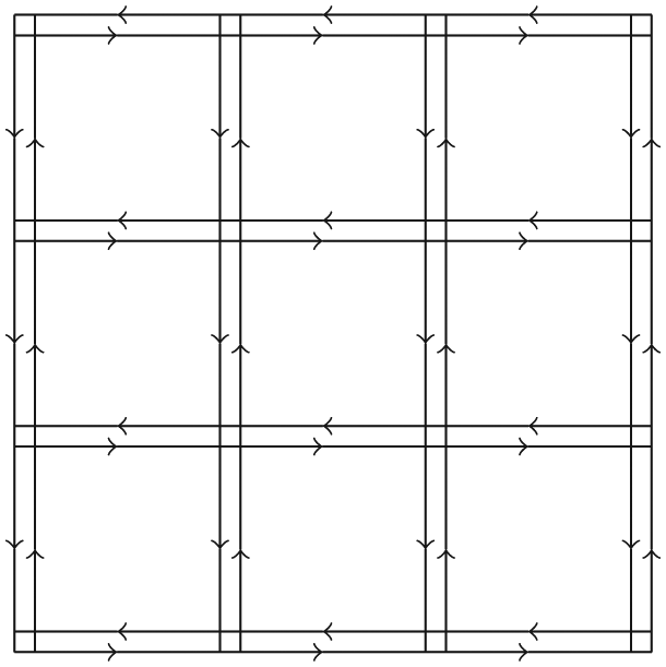
An example of a Manhattan Grid topology with double-way roads.
Discussion
For MG it is very clear that for several UAV scenarios, this model is not suitable. Although this model provides flexibility for the nodes to change the direction, it imposes geographic restrictions on nodes’ mobility. The same considerations for the first three mobility models can also be taken in MG considering the sharp turns and speed.
Time-dependent mobility model
This category of mobility models tries to avoid sharp speed and sharp direction changes. The smooth change of motion can be performed using different mathematical equations.
Boundless Simulation Area
Description
The Boundless Simulation Area (BSA) mobility model
36
uses a relationship between the previous direction and speed and the current ones. For each mobile node, through a vector

where


The movement into the simulation area boundary is handled differently from the other mobility models: when a mobile node reaches one side of the simulation area, it continues to travel and reappears on the opposite side of the simulation area. An example of the BSA movement is shown in Figure 5, where

Pattern of a mobile node using the Boundless Simulation Area mobility model.
Discussion
BSA allows the mobile nodes to move unobstructed in the simulation area, removing any edge effects on the simulation evaluation. However, several simulation scenarios could find undesirable the no-side effects that occur from the moving out of an edge and entering from another one. In applications where the mission area is simply a two-dimensional shape and the study of relationship between mobile nodes is prominent, this model would not meet the necessary conditions because of the teleportation effect inherent to the model. 14
Gauss–Markov
Description
The Gauss–Markov (GM) mobility model
37
uses several parameters that are tuned to adapt the model to different levels of randomness. At start, each mobile node is set with a current speed and direction. Then, at each time instance


where


Figure 6 illustrates an instance of the GM mobility model, with

Pattern of a mobile node using the Gauss–Markov mobility model.
Other versions of the GM mobility model were proposed; they modify the original equations with other variables, functions, and constants. In addition, a 3D version of GM is defined in Broyles et al. 38
Discussion
GM is able to reduce the sudden stops and sharp turns that we can note in RW, RWP, and RD. This is possible thanks to the equations system that relates the past speed and direction with the future ones, allowing a smooth update if appropriate parameters are chosen. However, this model cannot reproduce a typical behavior of UAVs (especially turns), and it is difficult to choose good parameters to make their movement more realistic.
Smooth Turn
Description
The Smooth Turn (ST) mobility model
39
allows the mobile nodes to move in flexible trajectories, correlating the acceleration of the mobile node across temporal and spatial coordinates. With this mobility model, each UAV chooses a point in the space and then circles around it until the UAV selects another turning point. The chosen point must be perpendicular to the UAV direction, to ensure a smooth trajectory. The duration for the aircraft to circle around the current turn point is modeled to be exponential distributed. The pattern performed with this mobility model can be seen in Figure 7, where an average speed of
Pattern of a mobile node using the Smooth Turn mobility model.
Discussion
Unlike traditional mobility models which force vehicles to make sharp turns, ST realistically captures the smooth movement patterns of airborne vehicles without placing additional constraints. We have noted some drawbacks: the lack of any collision avoidance mechanism and boundary reflection effects due to the impact of the mobile node on the area boundaries, which forces the node to suddenly change its direction.
Path-planned mobility models
These mobility models deploy a certain predefined path in order to force the UAVs to follow it. Especially, each UAV follows a specific pattern until it arrives at the end; at this point, the UAV randomly changes the pattern or repeats the same one.
Semi-Random Circular Movement
Description
The Semi-Random Circular Movement (SRCM) mobility model
16
is designed for the curved movement scenarios of UAVs. It is suitable for simulating UAVs turning around a specific. In the SRCM model, each node
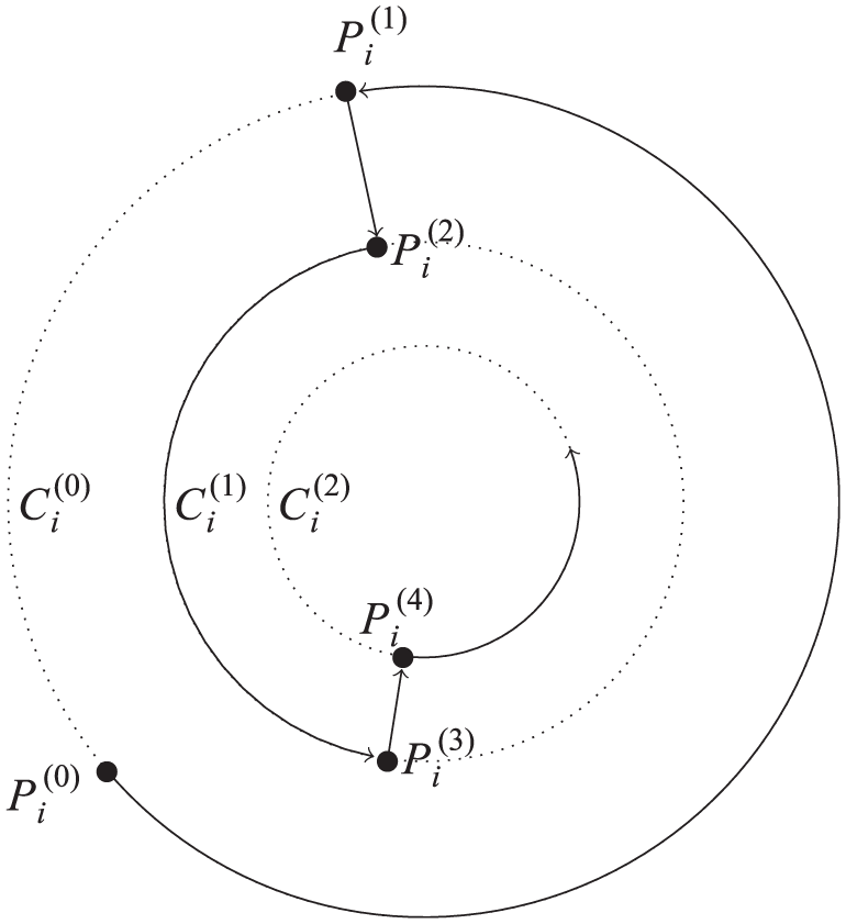
An example of pattern traveling performed by a node
Discussion
A particular strength of SRCM is the reduction of potential collisions between UAVs due to the circular nature of the movement, compared with any trivial random mobility model. However, the change of the turn radius leads to an orthogonal sudden change of direction, being clearly not realistic from the UAV perspective.
Paparazzi
Description
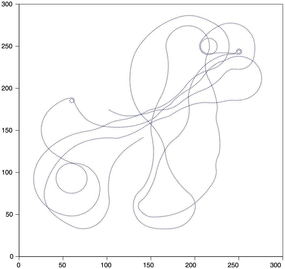
The Paparazzi mobility model (PPRZM) 40 is a stochastic mobility model that imitates Paparazzi UAV behavior in the Paparazzi autopilot system. 41 It is based on a state machine containing six movement pattern states: Stay-At, Eight, Oval, Scan, and Way-Point. At the beginning, each UAV chooses a movement type, its start position, and the speed. Then, it chooses and fixes a random altitude, which remains constant for the entire simulation. Figure 9 shows the different movement patterns of PPRZM. In Thounhom and Anusas-amornkul, 42 a study of several routing protocols using PPRZM is provided.

All the path schemes defined in the PPRZM mobility model: (a) Way-Point, (b) Eight, (c) Stay-At, (d) Scan, and (e) Oval.
Discussion
PPRZM tries to face the problems of Pure Randomized mobility models providing a set of well-defined pattern schemes that simulate some real UAV movements. The authors in Bouachir et al. 40 sustain that these pattern schemes are closer to the behavior of real application scenario traces, compared to a simple RWP. On the other hand, the simple state machine, through which the movement pattern for each UAV is chosen, is too casual for a specific mission planning. Initially, the UAVs’ positions are chosen randomly and lack a specific organization among their pattern movements. Furthermore, when a UAV finishes the first pattern scheme and enters in the second one, depending on the rotation angle of the schemes, the UAV could get a sharp curve, breaking the smooth characteristic of the model.
Group Mobility Models
Group Mobility (GM) models include a spatial constraint among all the mobile nodes. In the previous sections, all the mobility models simulate the behavior of mobile nodes that are completely independent of each other. However, in FANETs, there are many situations where it is necessary that UAVs move together following a common point, introducing a spatial dependency between them. For example, a group of UAVs can follow a common line that moves along with time, in order to patrol a specific large area. Typically, this group formation is planned to accomplish a common goal. The Reference Point Group Mobility (RPGM) 43 model simulates a random motion of mobile nodes within a reference group. The reference group, represented by its logical center, moves on the area by following a simple RWP model. Its motion consequently characterizes the speed and direction of its corresponding group of mobile nodes. In particular, at each time step, the location of each mobile node is updated according to the logical center of the reference group; then, the random vector is combined with the updated location, in order to diversify the behavior of all the group’s nodes. In the following, three mobility models are described as special cases of the general RPGM.
Column mobility model
Description
In Sánchez and Manzoni,
44
the Column (CLMN) mobility model is proposed for scanning or target searching application scenarios. Each mobile node moves around a reference point placed on a given line, which is moving in a forward direction. In particular, each mobile node randomly turns around the reference point through an entity mobility model, for instance, a simple RW. Figure 10 illustrates an example of CLMN, where three mobile nodes randomly move around their own reference point placed on a line, which moves and turns. At each time interval, the new position of each reference point is calculated taking into account the old reference point’s position and the advance vector of the line, identified by a random distance

Example of a single-step movement using CLMN, in which a set of three reference points are fixed to a line, which moves for

Pattern of three mobile nodes using the Column mobility model.
Discussion
The Group Mobility models could represent many realistic scenarios involving UAVs. The spatial constraint defined by these models can allow a guaranteed connection among the UAVs within each group. CLMN can prevent collision between UAVs, since each UAV moves around a fixed point, being these points placed far from each other. However, smooth turns and speed changes are not present in this mobility model.
Nomadic Community mobility model
Description
In the Nomadic Community (NC) mobility model, each mobile node moves randomly around a given reference point, without any constraint (as in CLMN). Figure 12 gives an illustration of five nodes moving around a reference point, which move, in turn, in a certain direction. The mobile nodes can move within a maximum distance

Example of a single-step movement using NC, in which five mobile nodes move around a moving reference point.

Pattern of three mobile nodes using the Nomadic mobility model.
Discussion
NC has nodes that share common spaces, producing collision events between UAVs. Modified versions of this mobility model can include additional constraints in order to initially divide the flying spaces, or to control the distance between the UAV pairs, in order to avoid collisions. Furthermore, even here we have sudden movements due to the changing direction and speed of mobile nodes and reference points. As in CLMN, smooth turns and speed changes are not taken into account.
Pursue mobility model
Description
The Pursue (PRS) mobility model is similar to NC. In this case, the mobile nodes attempt to follow a particular target that moves in a certain direction. The mobile nodes use a simple random relative motion while pursuing the target. We can imagine, for example, police officers that try to follow and catch escaped criminals. Figure 14 shows an example of PRS movement, where five nodes (in white) represent the pursuing nodes that follow the pursued node (in black).

Example of a single-step movement using PRS, in which five mobile nodes follow the moving black pursued target.
Discussion
PRS is very similar to the NC; hence, it shares the same characteristics.
Topology-control–based mobility models
A real-time control of UAVs’ motion is needed when certain network or mission constraints have to be continuously satisfied. One constraint is to maintain a fully connected network of UAVs at all times, so that a given UAV can talk with any other. In this case, a continuous motion control of UAVs according to the network connectivity level is mandatory. Topology-control mobility models are the new generation of mobility models for FANETs, since they enable network topology control through sensible data transmission in the network itself. In this way, the randomized nature of mobility is removed, being replaced by a control solution that is more robust and aware of the UAVs movement according to the mission objectives or network constraints. In Messous et al., 45 the development of a distributed mobility model for UAVs considering connectivity and area coverage is proposed. We present some existing typical swarm models proposed in the literature that could be applied for deploying and controlling groups of UAVs.
Distributed Pheromone Repel
Description
In Kuiper and Nadjm-Tehrani, 22 the Distributed Pheromone Repel (DPR) mobility model is proposed, with the aim of describing a robust and random movement of UAVs that perform reconnaissance to detect hostile ground targets. Each mobile node maintains its own pheromone map, which is a grid of the area where each cell contains a timestamp representing the last time the cell was scanned. Once a mobile node scans an area, it marks that area on the map. The information of scanned areas (the local pheromone maps) is regularly broadcast among the mobile nodes. When a mobile node has to move, it can go straight, turn left or turn right, according to its pheromone map.
Discussion
DPR is able to reproduce a realistic movement thanks to the smooth turns and the objective pheromone map. The problem is that the network connectivity is not considered. An evolution of this mobility model can be the enhancement of the pheromone map including a connection density with the other UAVs, to counterpoise the target pheromone map for the mission.
Self-Deployable Point Coverage mobility model
Description
A self-organizing FANET is proposed in Sanchez-Garcia et al. 46 for disaster scenarios. Self-Deployable Point Coverage (SDPC) mobility model deploys a set of UAVs on a disaster area in order to create a communication infrastructure that the victims of the disaster event can use. The aim of each UAV is to cover the maximum number of people on the ground maintaining a connection with the other UAVs.
Discussion
SDPC is a good compromise between target coverage and connectivity, since the UAVs try to reach the target victims while also taking into consideration the connectivity between themselves. However, the simulation of the proposed model is performed without a realistic movement (smooth acceleration and turns) of UAVs. Although an explicit collision detection procedure is not integrated in this model, own functioning prevents UAVs from approaching each other, since they tend to move so as to cover the maximum possible area. On the other hand, a building/obstacle collision control could be necessary.
Representativeness of existing mobility models
When flying devices are considered, we have to define specific characteristics about their movement. Due to the nature of the aerodynamic and mechanical flight, the motion behavior of UAVs is difficult to be recreated on simulators. The motion of an UAV is determined by several factors, such as the path, the speed, the atmospheric condition. Trivial mobility models, like RW, do not take these issues into consideration. A first aspect is the curve of an UAV, which is reproduced by many simple mobility models as a generic sudden change of direction, compared with a realistic curve, which is smooth. Then, a realistic flying device has an acceleration and deceleration while changing its speed. Finally, it could have micro variations in its motion due to turbolences or speed differences between the different propellers. These characteristics are not simulated in several mobility models, which simply change the speed with an infinite acceleration. Finally, safety requirements, like safety distance to avoid collisions, should be taken into consideration. In Table 1, we illustrate these characteristics and indicate which mobility models can satisfy them. Table 2 shows a list of the available mobility model generators and network simulators, including all the mobility models supported by each of them.
Mobility models and their related realistic and network characteristics.

RW: Random Walk; RWP: Random Waypoint; RD: Random Direction; MG: Manhattan Grid; BSA: Boundless Simulation Area; GM: Gauss–Markov; ST: Smooth Turn; SRCM: Semi-Random Circular Movement; PPRZM: Paparazzi mobility model; CLMN: Column; NC: Nomadic Community; PRS: Pursue; DPR: Distributed Pheromone Repel; SDPC: Self-Deployable Point Coverage.
Networks simulators and mobility generators with implemented mobility models (N.A: information not available).
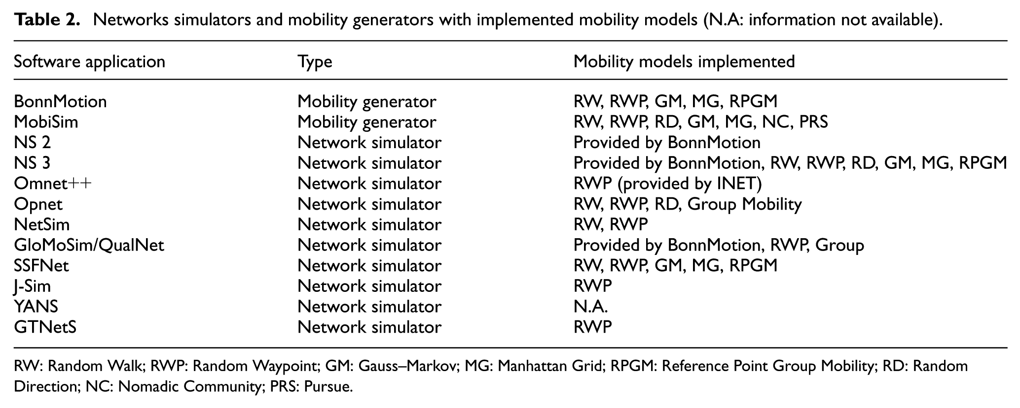
RW: Random Walk; RWP: Random Waypoint; GM: Gauss–Markov; MG: Manhattan Grid; RPGM: Reference Point Group Mobility; RD: Random Direction; NC: Nomadic Community; PRS: Pursue.
Application scenarios and mobility models
In this section, we illustrate which mobility models can be adequate for the above defined application scenarios and their special cases. For each mobility model applied in the considered scenario, we explain for which type of FANET application it could be applied, along with its limitations in terms of realism, connectivity, and collision avoidance.
In Table 3, a summary of application scenarios and feasible mobility models associations is shown. RW, RD, RWP are generic and too simple mobility models that are based on stochastic movement. They do not reflect any particular kind of movement to reach any task. The nodes simply move randomly, with a linear trajectory, stopping suddenly and then restarting the movement. There is no acceleration model nor a Smooth Turn model. Every one of these models can be used when there is no need to consider a particular application, but to analyze network performance on a generic MANET, with a certain tolerance. In Figure 15, we show an example that allows comparing speed variations throughout time for the standard RWP model, and the equivalent speed changes under traces obtained using the software in the loop (SITL) simulator, 48 which are more realistic. We can see a huge difference between the two speeds, and, as mentioned, we note the sharp speed changes in the case of RWP. Hence, in Table 3, these three models are not taken into consideration.
Mobility models feasibility for FANET application scenarios.

BSA: Boundless Simulation Area; GM: Gauss–Markov; ST: Smooth Turn; PPRZM: Paparazzi mobility model; SRCM: Semi-Random Circular Movement; DPR: Distributed Pheromone Repel; SDPC: Self-Deployable Point Coverage; MG: Manhattan Grid; PRS: Pursue; DPR: Distributed Pheromone Repel; CLMN: Column; PPRZM: Paparazzi mobility model; UAV: unmanned aerial vehicle.
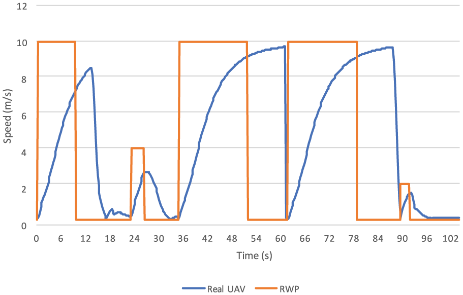
Speed variation differences between a real UAV and a simulated UAV using the RWP mobility model.
Search and rescue
A typical pattern for search and rescue operations is a simple scan scheme derived from PPRZM, when a rectangular search area is defined. Using multiple UAVs to speed up the task completion, it is possible to plan a multiple search scheme based on scanning. A requirement for this type of solution is UAV connectivity: the scan scheme of each UAV has to be planned according to the others, in order to maintain a connected UAV network as much as possible. Another pattern is a circle scheme, like SRCM, which restricts UAVs to turn around a fixed target as a potential search target location.
BSA, GM, or PPRZM can reproduce a randomized search task in a well-defined area. BSA has the unrealistic teleportation feature when an UAV gets out from the area. To tackle this problem, when the UAV goes out the area, each UAV needs to delay the time to re-enter. The randomized nature of mobility models brings the problem of connectivity and collisions. In that case, a study of network connectivity compared to the network node density is needed, especially in emergency search scenarios, which requires a guaranteed delivery and a maximum delay limit.
A more robust mobility model for search and rescue scenarios is the DPR mobility model, in which the movements depend on the areas visited by UAVs. In this case, UAVs need a strong connectivity in order to guarantee a good packet delivery for the coordination between UAVs.
In a disaster scenario, occurring for example after an earthquake event, eventual victims are sparsly distributed on the ground. SDPC is the most useful mobility model specifically designed for these events, because it allows the UAVs to reach the victims taking into consideration their connectivity.
Forest fire detection
A simple scheme for UAVs in detecting forest fires is SRCM, where UAVs turn around a forest area with different radius. However, DPR can be used by UAVs that are equipped with specific sensors. They can fly above areas that present particular physical quantities (temperature, humidity, infrared signals, etc.), upgrading their pheromone maps according to these data, and moving toward more affected areas.
Another scenario to consider is the case in which a fire is ongoing, and the firefighters are proceeding to extinguish it; a swarm of UAVs can move on the fire edge to monitor and follow its progress. In this case, a Group Mobility model, in particular CLMN, can be used and adapted to the fire edge.
Traffic and urban monitoring
For urban scenarios, we could have different applications. If we need a surveillance infrastructure on crossroads, UAVs can be positioned stationary as fixed cameras on each crossroads to monitor some events; in this case, a simple Static model can be used.
If we need moving UAVs to turn around the urban area, an MG mobility model could be adequate for this purpose. In this case, most of the attention focuses on the connectivity among UAVs, since MG does not support topology control, and for real-time surveillance, it can be a critical point to resolve; a possible solution comes from the introduction of other UAVs with a topology control mechanism that can act as relays for urban monitoring through UAVs.
Another scenario that can represent a more specific event is a car accident. A group of UAVs may reach the area before help arrives, in order to check the victims state and detect any dangerous situations. SRCM may be suitable for this type of scenario.
Reconnaissance and patrolling
First line of defense patrol is a typical usage of UAVs that fly in a stationary mode to oversee a specific area. UAVs can also replace people or cars patrolling periodically around a specified target (buildings, people, ground vehicles, etc.); when a mission needs of such type of target surveillance, SRCM may be used. When these targets also move, a Group Mobility model can satisfy a simulation of this behavior. The specific Group Mobility model adopted (CLMN, NC, or PRS) depends on the target number and behavior. For instance, if a group of ground vehicles proceed along a street, UAV movement can be simulated with CLMN, or PRS, if the target must be pursued by UAVs.
For reconnaissance missions over a specified area, simple random motions can be used. In fight-flight principles, each UAV travels to the involved area and then gets out by returning to the base station. BSA or GM is good mobility models for these applications since they produce random paths not predictable by enemies. For missions in which a certain cooperation among UAVs is needed, the DPR mobility model includes a map of attraction points that can represent sensible areas (people concentration, lively areas, areas at risks, etc.).
Agricultural management
Typically, agricultural scenarios require a one-time movement. For actuator UAVs (performing irrigation or disinfection tasks), a scan pattern from PPRZM can be adequate, due to the rectangular nature of the operation areas like cultivated fields. Alternatively, CLMN can be appropriate to check the field area conditions.
Environmental sensing
UAVs as sensor nodes are placed stationary on the area to be sensed, periodically sensing environmental information to the base station. Applications for sensor networks are typically performed by DTNs, which do not need real-time communication or continuous network connectivity.49,50 Alternatively, each UAV can move by following a predefined path scheme, where each waypoint is located near a static sensor; the moving UAVs gather the data from each sensor (via a wireless connection) and then return to the base station. This case suggests the adoption of a path-planned mobility model, like PPRZM, which can be eventually customized to adapt it to the desired path scheme (e.g. a path that covers all the sensors on the area).
Relaying network
The request for a communication infrastructure where there is no connectivity can be performed by statically deploying a set of UAVs, which act as a relay chain among UAVs, or even in a heterogeneous scenario involving UAVs, vehicles, pedestrians, and so on.51,52
In urban scenarios, UAVs can be used as routers for V2V connectivity, allowing vehicles on the streets to communicate with each other; a simple MG model can represent such scenario.
Conclusion
Mobility model selection strongly depends on the type of simulation and application scenario that is involved in a FANET analysis. The performance of a FANET (e.g. packet delivery and packet delay) can vary significantly with different mobility models, and the choice of a suitable one is crucial for critical applications.
In this article, we have explored several mobility models, extracting their advantages and disadvantages in terms of motion realism, randomization, network connectivity, and collision avoidance. Pure randomized mobility models are trivial and too unrealistic for applications that engage flying devices. The inclusion of smooth turns and speed changes could reproduce more realistically these randomized movements. We explored some topology-control–based mobility models, which include a mission-based movement for UAVs.
Furthermore, we have associated the most fitting mobility model with each application scenario, so as to provide guidelines to researchers creating simulation experiments about drone ad-hoc networks.
Future research
In the future, further research on mobility models can of course be done. Randomized mobility models can be modified with the inclusion of smooth characteristics in order to add a realistic flight behavior. Another research branch can be devoted to a deeper examination of flying devices’ motion in the real world to reproduce more accurate mobility models. A good approach is the attempt to combine the existing mobility models, in order to merge the best movement characteristic of each of them. For example, the MG mobility model could include additional features coming from the ST mobility model, to reproduce more smooth curves when an UAV approaches a crossroad.
Also, we noted that to the best of our knowledge, there are no mobility models that consider collisions against buildings or other external obstacles. For example, a randomized mobility model that considers prohibited flying areas can implement such scenarios. A particular consideration could be taken in this direction. Finally, we would also like to investigate how different mobility models and routing strategies may affect the QoS of the considered applications. 53
Footnotes
Handling Editor: Paul Mitchell
Declaration of conflicting interests
The author(s) declared no potential conflicts of interest with respect to the research, authorship, and/or publication of this article.
Funding
The author(s) received no financial support for the research, authorship, and/or publication of this article.