
Abstract
In the past decades, the unmanned aerial systems have been utilized only for military operations. However, recently, the potential uses and applicability of unmanned aerial vehicles (commonly known as drones) in civilian application domains are becoming a fast-growing phenomenon. A flying ad hoc network is a wireless ad hoc network specifically designed for the communication of unmanned aerial vehicles. Multicast routing is one of the vital aspects in wireless ad hoc networks. Using multicast transmission approaches, flying ad hoc network applications may need to send the same message to a specific group of flying nodes. The multicast communication approaches can benefit flying ad hoc network applications in conserving the scarce resources of flying nodes. Research works have been proposed to tackle the challenges in multicast routing with multi-hop communication in ad hoc network environments. Nevertheless, the conventional multicast routing mechanisms incur excessive control message overhead when a large number of nodes experience frequent topological changes. A scalable geographic multicast routing mechanism, which specially require localized operation and reduced control packet overhead, is necessary. Multicast routing in flying ad hoc networks is extremely challenging because of the dynamic topology changes and network disconnection resulted from frequent mobility of nodes. In this article, we present and implement a scalable and predictive geographic multicast routing mechanism in flying ad hoc networks. In uniform and random deployment scenarios, the MATLAB-based evaluation result has revealed that when the communication range increases, the probability of finding one-hop predicted forwarders to reach multicast destinations also increases. The implementation of scalable and predictive geographic multicast routing mechanism in flying ad hoc network is done using Optimizing Network Engineering Tools Modeler 16.0. We have added the scalable and predictive geographic multicast routing mechanism in flying ad hoc network as a new routing scheme in the Mobile Ad hoc Network routing protocol groups of the Optimizing Network Engineering Tools Modeler. Then, the performance of scalable and predictive geographic multicast routing mechanism in flying ad hoc network is compared with two of the existing Mobile Ad hoc Network routing protocols (Geographic Routing Protocol and Dynamic Source Routing). Eventually, we present two instance scenarios regarding the integration of scalable and predictive geographic multicast routing mechanism in flying ad hoc network scheme in the Internet of Things platform.
Keywords
Introduction
Recently, many research literatures in the fields of electronics technology, wireless and mobile network communications have been focusing on unmanned aerial system (UAS). The UAS encompasses unmanned aerial vehicles (UAVs or commonly known as drones), control centers, and other necessary communication and navigation equipment that are helpful for the safe operation of drones. In the past decades, the UAS has been utilized only for military operations. However, today, the potential uses and applicability of drones in civilian application domains such as air pollution monitoring, 1 package delivery (e.g. Amazon Prime Air), 2 healthcare delivery, 3 environmental monitoring, 4 surveillance, 5 disaster management,6–9 search and rescue missions,10–13 agriculture (crop and soil condition inspection), 14 industrial service automations, weather, archeology, sport, forest fire monitoring and detection,15–17 traffic monitoring,18,19 security, tourism (guiding tourists in video recording from different view and photograph taking), remote exploration, mining and infrastructure (geospatial data gathering), illegal fishing monitoring (hunt down illegal boats netting fish), and helping the disabled (through utilizing drone-based audio and video streaming services) are becoming a fast-growing phenomenon.
Flying ad hoc network (FANET), 20 which is considered as a subset of mobile ad hoc network (MANET), is a wireless ad hoc network established by UAVs or drones as wireless communicating mobile nodes. In a multi-UAV system, drones have potential benefits in wireless communication while delivering data from the air to one or more ground stations as well as directly among the drones, where drones’ cooperation and collaboration toward accomplishing the target mission is important. Such multi-UAV mobile communication can be materialized using FANETs.
The design of multicast routing scheme is one of the vital aspects in wireless ad hoc networks for the transmission of messages between flying objects. In multicast routing, the messages are sent to multiple specified destination nodes from a single source through utilizing multiple intermediate forwarding relay nodes. This routing technique reduces transmission overhead, control message overhead, power consumption, and network partitioning. Using multicast transmission approaches, FANET applications may need to disseminate multicast messages to a specific group of flying nodes. The main goal of multicast routing protocols in FANETs is establishing an efficient path between the source and multiple multicast destination nodes.
In the field of wireless ad hoc networks, geographic-based routing schemes have become important due to their localized operation, reduced computation, and storage overhead, and scalability with the required number of nodes.21,22 Geographic multicast routing mechanisms with reduced control message overhead and efficient bandwidth consumption are necessary for GPS-enabled flying nodes in FANETs. The literatures in Bekmezci et al., 20 Sahingoz, 23 Yassein and Damer, 24 and Motlagh et al. 25 discuss various comprehensive research issues regarding FANETs. Nevertheless, in these papers, the issues of geographic-based routing protocols in FANETs are not covered in detail.
Research works in Bose et al., 26 Karp and Kung, 27 Lin et al., 28 Momma et al., 29 Lee et al., 30 and Oubbati et al. 31 have been proposed in the field of wireless and ad hoc networks with the aim of devising efficient geographic-based routing schemes. These schemes, however, have limitations when considering the mobility aspect.32,33 Reactive beaconless geographic routing schemes34–40 have been proposed as solution to alleviate the limitations encountered in dynamic network topologies. However, the design and development of efficient multicast routing scheme in FANETs are extremely challenging due to highly dynamic topological change, high bandwidth and power consumption, frequent network disconnections and partitioning resulted from frequent mobility of nodes. In FANETs, frequent topology changes are observed due to the fast velocity of drones (moving at a speed of 30–460 km/h) 41 and high degree of mobility. 20 In other words, the mobility degree of drones that fly in the sky is much higher than that of nodes in a typical vehicular ad hoc network (VANET) and MANET. Thus, it is difficult for the network nodes to maintain the global multicast routing information and existing ad hoc routing protocols such as optimized link state routing (OLSR) 42 protocol lack proper functioning when frequent network topological changes are encountered.
Accordingly, in this article, we present an extension to our previous works43,44 on a scalable and predictive geographic multicast routing scheme in flying ad hoc networks (SP-GMRF) through implementing it using Optimizing Network Engineering Tools (OPNET) Modeler and then adding it as a new routing scheme in the MANET routing protocol groups of the OPNET Modeler. In addition, to show the performance gain achieved by SP-GMRF scheme, its performance is compared with two of the existing MANET routing protocols—geographic routing protocol (GRP) and dynamic source routing (DSR). The performance evaluation of these protocols is done based on the rate of ftp (high load) application traffic while changing the number of flying nodes in different simulation scenarios. Furthermore, this article describes two instance scenarios regarding the integration of the SP-GMRF in the Internet of Things (IoT) platform. Our scheme is designed by taking the greedy geographic routing approach into consideration and it can also be used with local maximum (void) recovery schemes mentioned in Karp and Kung 27 and Kuhn et al. 45
In a nutshell, the contributions of this article are as follows:
We provide the data structure and detail explanation of the proposed predictive geographic-based multicast routing scheme in FANETs called SP-GMRF.
We provide step-by-step approaches for adding the SP-GMRF as a new routing scheme in OPNET Modeler which, in turn, is helpful for researchers who want to implement their proposed protocols in OPNET Modeler.
We provide example scenarios on the integration of SP-GMRF scheme in the IoT platform.
The remainder of this article is organized as follows. Section “Related work” presents related literatures. Section “The proposed geographic multicast routing scheme in FANETs” presents the problem formulation, forwarding neighbor node location prediction, and the proposed geographic multicast scheme along with its data structure and deployment scenarios-based descriptions. Performance analysis and instance application scenarios are described in section “Performance analysis.” Finally, conclusion is made in section “Conclusion.”
Related work
Multicast routing is one of the basic routing mechanisms utilized by many applications in wireless network environment. Various types of multicast routing protocols have been proposed for wireless networks communication. In Farooq et al., 46 an autonomous military vehicles routing (AMVR) protocol for the multicast communication among unmanned and manned military vehicles in VANET have been proposed. In order to minimize the network overhead during message dissemination, the AMVR utilized a two-tier approach where unmanned military vehicles belong to the first tier and manned military vehicles are grouped in the second tier. The paper work in Farooq et al. 47 surveyed the multicast routing protocols together with their applications, merits, and demerits in VANET environment. It also discussed multicast-based geocast routing protocol developed for vehicular communication. The geocast approach uses geographic location of nodes for transmitting messages from a single source to multiple destinations. As a feasible solution to the high cost and difficulty incurred in installing huge infrastructures (e.g. Road Side Units) on all roads and highways, this article mentioned the importance of installing ad hoc network for inter-vehicle communication. The geographic multicast routing (GMR), presented in Sanchez et al., 48 improved location-based forwarding efficiency through utilizing the multicasting approach. However, it suffers a lot when dealing with scalability issues in large-scale networks. In order to tackle the scalability problem, hierarchical multicast routing schemes49–51 have been proposed. In these schemes, the network region is subdivided into zones and each zone has a group leader responsible for managing multicast group members. When a source node intends to send multicast messages to members, it adds group leaders’ information on message header and sends it to group leaders. Nevertheless, group leader election process as well as membership management tasks in each zone incur additional overhead and it is challenging when we consider a large-scale network with dynamic network topology. As a solution to GMR problem, the article in Won and Stoleru 52 also presented a robust and energy-efficient hybrid multicast routing (RE2MR) protocol for large-scale wireless sensor networks. Similar to the void recovery schemes mentioned in Karp and Kung 27 and Kuhn et al., 45 this multicast routing protocol has considered the issue of network irregularities such as network holes encountered on static wireless sensor network environment.
Nowadays, a great number of research works in the fields of electronics technology, wireless and mobile network communications focusing on UAVs have been attracting the attention of many researchers. In multi-UAV system, dealing with routing aspect, which is one of the crucial constituents in network communications, is necessary for guaranteeing reliable message communication among collaborative drones themselves and control station while performing a specific target mission. As mentioned in Yassein and Damer, 24 the routing protocols designed for wireless and ad hoc networks need not be used as it is unless they are modified to fit with the unique behavior of UAVs such as rapid topological changes. As per this article, if not modified, conventional proactive routing protocols are not applicable for highly mobile networks like FANETs due to high bandwidth consumption resulted from message overhead during routing table updates. Accordingly, choosing appropriate routing scheme for multi-drone communication in FANET is challenging. In Sahingoz, 23 the challenges of using drones as relay nodes in an ad hoc fashion are identified and the need for a scalable ad hoc network among the drones and ground stations is mentioned. The authors in Tareque et al. 53 have critically analyzed and compared six of the existing routing protocols for FANET—static, proactive, reactive, hybrid, geographic, and hierarchical routing protocols—based on performance metrics such as complexity, fault tolerance, signal overhead, memory size, topology size, popularity, and communication latency. However, multicast routing among multi-drones is challenging due to the frequent topology changes that are resulted from the fast speed of drones.
Several research activities have been conducted in the field of wireless network with the aim of devising efficient geographic-based routing schemes.26–31 The network nodes in the existing research works on geographic routing schemes are supposed to maintain location information of its one-hop neighbors through periodically broadcasting beacon messages. These schemes have limitations when considering the mobility issue.32,33 Reactive (on demand) beaconless geographic routing schemes have been proposed as solution to alleviate the limitations encountered in dynamic network topologies.34–40 In Mauve et al., 54 a geolocation-based multicast routing has been proposed as a multicast solution in MANET environment.
Nevertheless, the design and development of efficient multicast routing scheme in FANETs are extremely challenging due to highly dynamic topological change, high bandwidth and power consumption, frequent network disconnections, and partitioning resulted from frequent mobility of flying nodes. The paper works in Sahingoz 23 and Tareque et al., 53 also considered the establishment of an ad hoc network between flying UAVs as a challenging issue since the routing requirement, for instance, can differ from the conventional networks such as MANET and VANET. Therefore, we propose SP-GMRF which is a predictive geographic multicast routing approach in FANETs.
As shown in Figure 1, the relationship among FANET, VANET, and MANET depicts that FANET is a subset of VANET and MANET. That is, despite the peculiar characteristics of FANET, there are common things that it shares with VANET and MANET.

FANET versus VANET and MANET.
Multicasting approach can enhance the network resource utilization through reducing the energy consumption and control message overhead of nodes. This is materialized through simultaneously transmitting a single copy of a message to multiple destinations or a group of nodes. To clearly understand the unicast versus multicast schemes in FANETs, we describe in Figure 2(a) and (b), an instance scenario of network resource utilization when multicasting and unicasting control messages by ground control station (GCS) to multiple destinations in FANETs.

Network resource utilization when multicasting and unicasting control messages: (a) GCS sending a single multicast control messages to UAV-1 and then UAV-1 forwards copies of the message to multicast destination UAVs (UAV-2, UAV-3, and UAV-4) and (b) GCS sending control messages to each of the destination UAVs (UAV-2, UAV-3, and UAV-4) using UAV-1 as a router. Therefore, UAV-1 has received three copies of the control message from GCS.
The proposed geographic multicast routing scheme in FANETs
In this section, first, problem definitions along with notations are presented. Then the forwarding neighbor node location prediction mechanism is presented. Eventually, we discuss the proposed scalable, on-demand, and predictive geographic multicast routing scheme in the FANETs.
Problem definitions and notations
In this article, we consider a FANET that consists of a source node S, multiple multicast destinations D, and forwarding nodes N. The source S acts as the root of the geographic multicast tree, D represents the multicast receivers, and N acts as forwarding neighbor nodes.
Let D be given as the set of n multicast destination (i.e. D = {D1, D2,…, Dn – 1, Dn}), N be the set of L forwarding neighbor nodes (i.e. N = {N1, N2,…, NL – 1, NL }), r be the transmission ranges of nodes, the source node S sends data packets to D using one-hop Ni ∈ N as forwarder if for each Dj ∈ D there exist an Ni ∈ N within r of S and the distance between
Suppose we model the multicast communication in FANETs as a graph G assuming that the network is three dimensional. Let G = (V, E) denotes a connected undirected graph with vertices V and edges E. In this graph, the vertex set V is composed of S, N, and D (i.e. V = {S, N, D}). For source node S and a neighbor node Ni ∈ N, the edge set E contains undirected edge (S,
The Euclidean distance between two points P1 and P2 in n-dimensional space is calculated as

where
Suppose, as it is explained before, N and D represents the set of L forwarding neighbor nodes and m multicast destinations, respectively. The minimum distance between the pair of N and D, denoted by
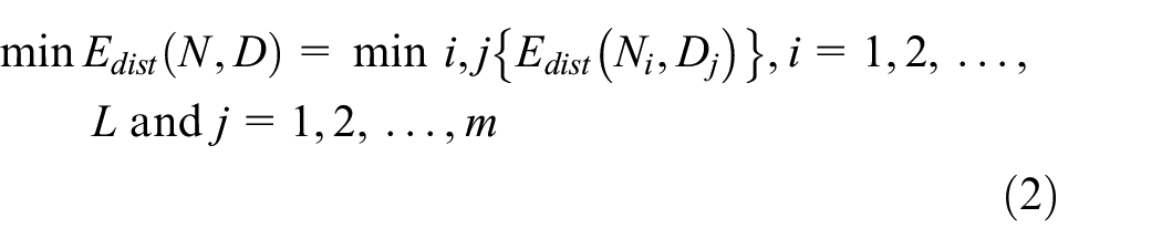
where
Given G = (V, E) and {S, N, D} ⊆ V, we need to find a geographic multicast routing tree that spans from a source S to all multicast destinations D through using a subset of N neighbor nodes as forwarders. Similar to the related works in Bose et al., 26 Basagni et al., 55 and Ko and Vaidya, 56 our scheme also assumes that S has knowledge of the geographical location of multicast destinations D.
Forwarding neighbor node location prediction
In order for the source node S to decide whether its one-hop neighbor node
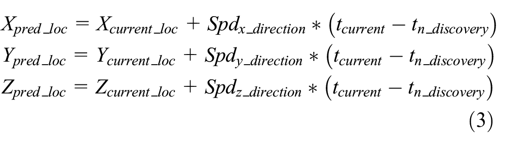
where

where
Note that it is necessary for the source S to only maintain the previous time and position information of neighbor nodes Ni ∈ N (i.e.
The SP-GMRF algorithm
In this section, we present the steps utilized by the SP-GMRF algorithm for creating a geographic multicast routing tree that spans the multicast group members through using a subset of multicast enabled neighbor nodes as forwarders. To maintain the scalability in the presence of frequent node mobility in a large FANETs environment, the SP-GMRF utilizes local information for constructing multicast routing tree structure. The source node only needs to store the latest geographical location, speed in the direction of x-, y-, and z-axis, and timestamp information of the neighbor nodes within its communication range. The source can discover this information through broadcasting a request to its one-hop neighbor nodes. The SP-GMRF algorithm is presented in Algorithm 1.

When a source node has data packets to be sent to multiple multicast destinations Dj ∈ D, the SP-GMRF algorithm, based on partial knowledge of the network topology and on-demand basis, commences the construction of geographic multicast tree structure. Here we assume that the source can obtain the position information of multicast destinations through some kind of location service and flying nodes are aware of their own positions. When the source node S wants to send data packets to multicast destinations
Data structures used in SP-GMRF
In this section, we describe the data structure of SP-GMRF. The SP-GMRF utilizes the data structure presented in Table 1 whereby the source collects all necessary information from its one-hop mobile nodes and the destinations. The source builds knowledge about its one-hop direct neighbor nodes position (i.e. x-, y-, and z-coordinate of nodes) through the exchange of periodic hello packets which carries information about nodes identification and position. The neighbor information entry is based on the data structure of Table 1 and it is maintained by considering the updated position of one-hop neighbors. Using this data structure, neighbor information could be (a) added when neighbors enter the communication range of the source, (b) updated as a result of computation, and (c) deleted when neighbors went outside the communication range of the source or when neighbors expiry time is reached.
Data structure to collect one-hop neighbor information.

After the construction of the gmTree through SP-GMRF algorithm, the source sends the data to multicast destinations by attaching the header information which encompasses multicast destination information (multicast destination address and location) and selected one-hop forwarder location pairs.
Description of SP-GMRF algorithm with example scenarios
In this section, we describe the working logic of SP-GMRF algorithm using example deployment scenarios of Figure 3. The scenarios contain 1 multicast source, 15 mobile nodes, and 5 destinations. The geographic multicast tree creation and data delivery phases of SP-GMRF are described as follows.

Deployed multicast source, mobile nodes, and destinations: (a) previous positions of mobile nodes, (b) current positions of mobile nodes, (c) predicted positions of mobile nodes, and (d) geographic multicast tree rooted at S.
Geographic multicast tree creation phase
The geographic multicast tree construction process commences reactively when a source S wants to send data to multicast destinations. In the scenarios of Figure 3, the SP-GMRF algorithm computes the predicted position of the mobile nodes by taking the destinations location, timestamp, velocity, previous location (Figure 3(a)), and current location (Figure 3(b)) information of the mobile nodes into consideration. The source utilizes the data structure shown in Table 1 while collecting all the necessary information from its one-hop mobile nodes. The instance values to the fields of the data structure are shown in Table 2.
Neighbor entries maintained by the source.

Using equations (1) and (2), we predict the position of mobile nodes assuming that the mobile nodes velocity is the same and the location coordinates are accurate. Out of the 10 one-hop mobile nodes (n1–n10) to the source S (as indicated in Figure 3(b)), after prediction, six mobile nodes (n5–n10) are left as candidate one-hop neighbors of the source to reach the destinations and three mobile nodes (n1—n4) are moved out of the communication range of the source (see Figure 3(c)). From among the candidate one-hop predicted mobile nodes, as seen from Figure 3(d), the source S selects n7 and n5 as one-hop forwarder nearest to the multicast destinations d1/d2 and d3/d4, respectively. For multicast destination d5, since the source S did not find one-hop mobile node nearest to d5 than itself, the source S initiated perimeter forwarding until it reaches a mobile node nearest to d5 than S. In this case, the source S selects n10 as its one-hop forwarder on the route to d5. Finally, the geographic multicast tree that spans from source S to multicast destinations d1–d5 is constructed (see Figure 3(d)). Communication overhead is observed in our scheme during local communication. For instance, in order to select the next hop node with good progress toward multicast destinations, the geographical location information (x-, y-, and z-coordinates) of one-hop neighbor nodes within the communication range of the source node should be communicated. Our proposed scheme does not employ global communication of position information.
Data delivery phase
The data delivery is accomplished through utilizing the constructed geographic multicast tree. Before sending the data, the source S adds header information about the multicast destination and the corresponding closest forwarder (the selected one-hop mobile node). Hence, the forwarders are supposed to forward the received data to the corresponding multicast destinations only.
When looking at Figure 3(d) in the instance scenario, the source S forwards the data together with the header information (as shown in Table 3) to n7, n5, and n10. Each forwarder then checks the information in the payload header of the received data and sends the data to the corresponding destination. For instance, in Figure 3(d), n7 checks the header information from the received data and forwards the data to multicast destinations d1 and d2 only. Eventually, data will be sent from source S to multicast destinations using the constructed geographic multicast tree.
Header entries.

Regarding overhead, very limited communication overhead is observed when the source locally collects necessary information such as geographical location (i.e. x-, y-, and z-coordinate of nodes) information from its direct one-hop neighbors and multicast destinations. For instance, in our scheme, when a source node intends to send multicast message toward multicast destinations, it only needs to select a subset of its one-hop neighbors as relay nodes. Therefore, in order to compute and select the predicted next hop neighbors with good progress toward multicast destinations, only the location information of multicast destinations and one-hop neighbors within the communication range of the source are supposed to be communicated.
Performance analysis
In this section, we first visualize and validate the performance of SP-GMRF using MATLAB 57 simulator and then implementation of the SP-GMRF in Optimized Network Engineering Tools (OPNET) Modeler 16.0 58 is described.
SP-GMRF in MATLAB
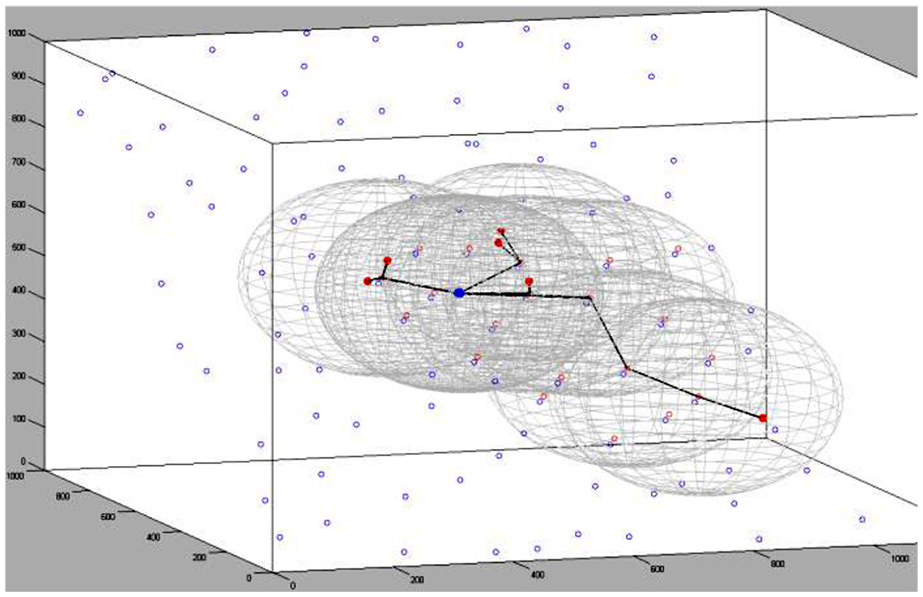
To visualize the mathematical abstractions and validate the performance of the SP-GMRF scheme, MATLAB 57 simulator has been utilized. As seen from Figure 4, a three-dimensional deployment region (1000 × 1000 × 1000) with the multicast source S located at position (500, 500, 500), six multicast destinations, and 100 multicast enabled nodes have been considered. The initial positions (x-, y-, and z-coordinates) of multicast enabled nodes are generated randomly as well as using uniform distribution approach where nodes are randomly distributed in each of the uniformly divided sub-grid. In both approaches, we have evaluated the number of predicted one-hop neighbors to the multicast source when the communication range varies (i.e. for r = 100, 200, 300, 400, 500, and 600). For instance, in a uniform distribution deployment scenario, as shown in Figure 4, when the communication range of nodes is 225, our scheme has computed 10 predicted positions for the one-hop neighbors to the source and out of which three predicted neighbors have been selected as one-hop forwarding relay nodes nearest to the multicast destinations. Since one of the multicast destinations which is located at far distance from the source cannot be reached using the selected one-hop forwarders, by taking the forwarder nearest to the multicast destination as a reference point, 10 more predicted positions have been computed and out of which two predicted nodes have been selected as forwarders to the multicast destination. From this, we can deduce that for a source node to cover the six multicast destinations, out of the 20 candidate predicted positions, six predicted nodes have been selected as forwarders toward multicast destinations. In the end, as shown in Figure 5, the geographic multicast tree that spans from the multicast source to multicast destinations across the selected forwarders is created by our scheme.

Uniformly deployed nodes and the computed candidate forwarders toward multicast destinations.
gmTree created by SP-GMRF scheme (in a uniform deployment scenario).
In both uniform and random deployment scenarios, with different position and communication range values of nodes, the SP-GMRF algorithm has been executed 10 times and the average result is taken for our evaluation. As depicted in the plot of Figure 6, in both cases, when the communication range of the multicast source increases, the average number of predicted one-hop neighbors to the multicast source has also increased. In case of uniform distribution scenario, when the value of r is between the ranges 100 and 500, the probability of getting predicted one-hop forwarders to reach multicast destinations is higher than the random distribution approach. This could be due to the existence of large number of one-hop neighbors to the source and the linearity of the distribution. In case of random distribution, nodes may be sparse in one location and dense in another location. When value of r is greater than 500, the average number of the computed predicted one-hop neighbors to reach multicast destinations in the random approach is greater than the uniform approach. This could have been resulted from the availability of large number of nodes at higher communication ranges. As to the computation cost, the larger the number of the predicted one-hop nodes is the higher the cost incurred at the source node while making computation for selecting the appropriate predicted nodes from among predicted one-hop neighbors nearest to multicast destinations.

Communication range versus number of predicted one-hop neighbors for uniform and random distribution approaches.
SP-GMRF implementation in OPNET Modeler
We model the SP-GMRF mainly using the process model of OPNET Modeler. 58 We create a new process model called sp_gmrf and define the routing protocol functionality of the SP-GMRF by utilizing our codes and transitions defined in the finite state machine (FSM). Implementation of the SP-GMRF is conducted in sp_gmrf process model through codes dispersed in the entrance and exit section of the FSM along with the codes in header, function, diagnostic, and temporary blocks of the process model. The required state and temporary variables to be used by different blocks of our process model are also defined. Partial view of the header and function blocks defined in the process model of SP-GMRF is shown in Figure 7.

SP-GMRF process model, header, and function blocks.
Then, we define the control packets and data structures of SP-GMRF in OPNET Modeler. The packet format of SP-GMRF is defined using the packet format editor of the OPNET Modeler. As mentioned before, SP-GMRF utilizes table-based data structures to store different kinds of information about the network nodes. For each data structure, a separate external file is created. Our implementation codes are mainly done in the header and function blocks of sp_gmrf process model. For instance, initialization of state variables, handling of control packet sending and arrival process, updating information of different data structures (tables), registration of statistics (local and global). The FSM is responsible for making the needed state transitions and function calls in the sp_gmrf process model.
In order to add SP-GMRF as a new MANET routing protocol to OPNET Modeler, we perform the following tasks:
Register SP-GMRF as one of MANET routing protocols. This is done by defining SP-GMRF in the ip_higher_layer_proto_reg_sup.h header file and manet_mgr (MANET manager) process model header block.
To configure SP-GMRF on the interface of network nodes, we include SP-GMRF in manet_mgr_routing_protocol_determine and manet_mgr_routing_process_create functions in the function block of manet_mgr process model.
Open the ip_rte_v4 header file and declare SP-GMRF in the IpT_Rte_Protocol enumerated type definition that describes the types of routing protocols.
As seen from Figure 8, the sp_gmrf_rte process model is registered and added as one of the child processes of manet_mgr process model.
In the interface model attributes of the manet_mgr process model, we define the SP-GMRF routing protocol parameters as one member of the Ad Hoc Routing Parameters group.
To enable the usage of SP-GMRF by the wireless network deployment wizard of OPNET Modeler, we include it by modifying the wireless_deploy_wiz_helper.xml file.

SP-GMRF added as one of the manet_mgr process model routing groups.
As shown in Figure 9, the application data packets from the upper layer go down to the IP layer for processing. The ip_dispatch process model of the IP routing process module sends the packet to its child process model called MANET manager (manet_mgr), where the SP-GMRF is incorporated as one of the child process models of the manet_mgr process model. We utilized the manet_mgr process model due to the reasons that it provides a common interface to multiple MANET routing protocols and also its extensibility for custom routing protocols. Once the SP-GMRF receives the packet, it conducts the forwarding neighbor route discovery task by sending control packet to the IP routing process through utilizing the ip_dispatch process model. Then, the IP routing process module forwards the control packet to lower layer (MAC/PHY) modules across its output interface. The IP routing process also receives the routing control packet from the lower layer (MAC/PHY) and passes it to SP-GMRF for further processing through utilizing the ip_dispatch and manet_mgr process models.
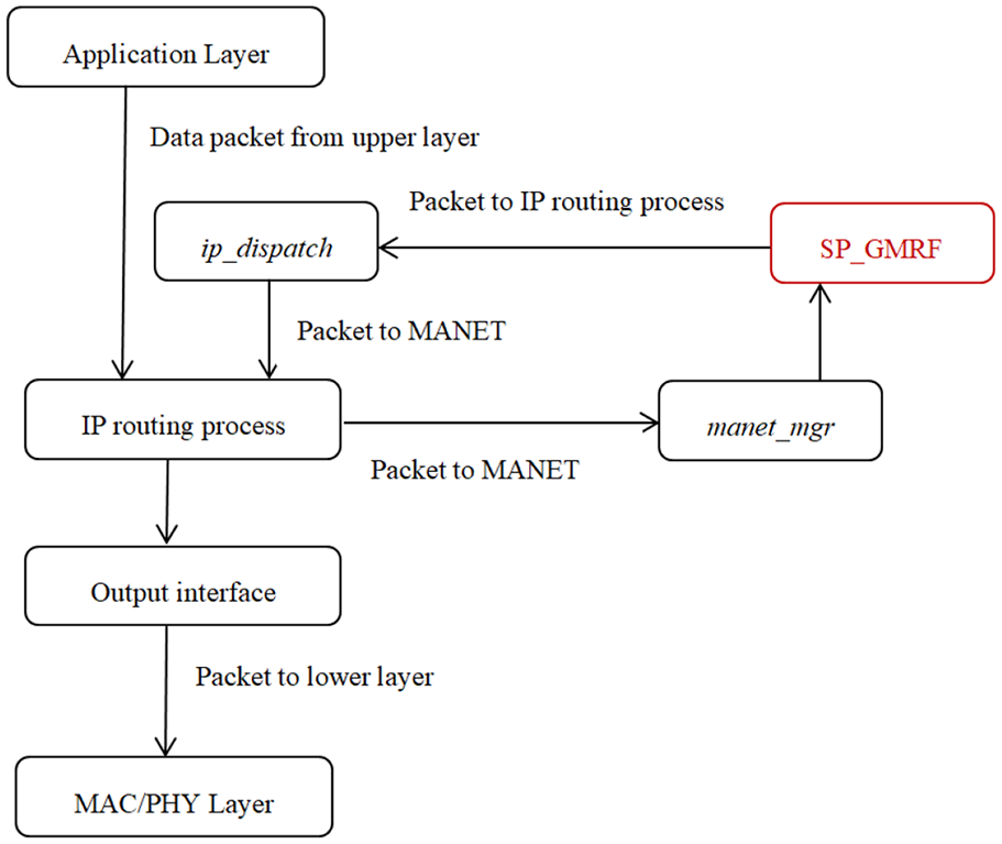
SP-GMRF in the IP protocol stack.
To clearly understand the above description, Figure 10 shows the manet_mgr as one of the child process models of the ip_dispatch process model in the IP module. Subsequently, as seen from Figure 8, the SP-GMRF is added as one of the child process models of the manet_mgr process model.
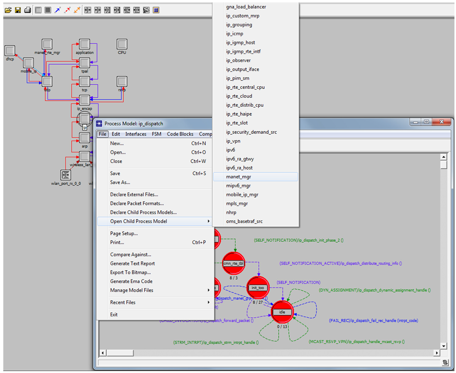
manet_mgr as child process model of ip_dispatch process model in the IP module.
Simulation environment and result
In our simulation environment, we employed OPNET Modeler 16.0 with different numbers of nodes randomly deployed in a deployment region. We divide the simulation into scenarios with 10, 20, 30, 40, and 50 number of nodes. Then, for each scenario and a routing protocol, we run the simulation for 3600 s using ftp (high load) application. Mobility models such as random waypoint (RWP) are not best suited for evaluating the routing protocols performance in FANETs. Hence, for modeling the mobility aspect, our simulation model utilizes predefined circular trajectory mobility pattern which we created it through MATLAB program and exported to OPNET Modeler as trajectory file. The circular trajectory file defines the customized flight pathways of flying nodes. The circular trajectory information is composed of six-dimensional coordinates (latitude, longitude, altitude, pitch, yaw, and roll), distance, speed, traversal time, and wait time values. The simulation parameters along with their corresponding values are summarized in Table 4. A sample deployment region, where 50 flying nodes and 5 destinations are randomly deployed together with trajectories, applications, and user profiles configurations, is shown in Figure 11.
OPNET simulation parameters and value.
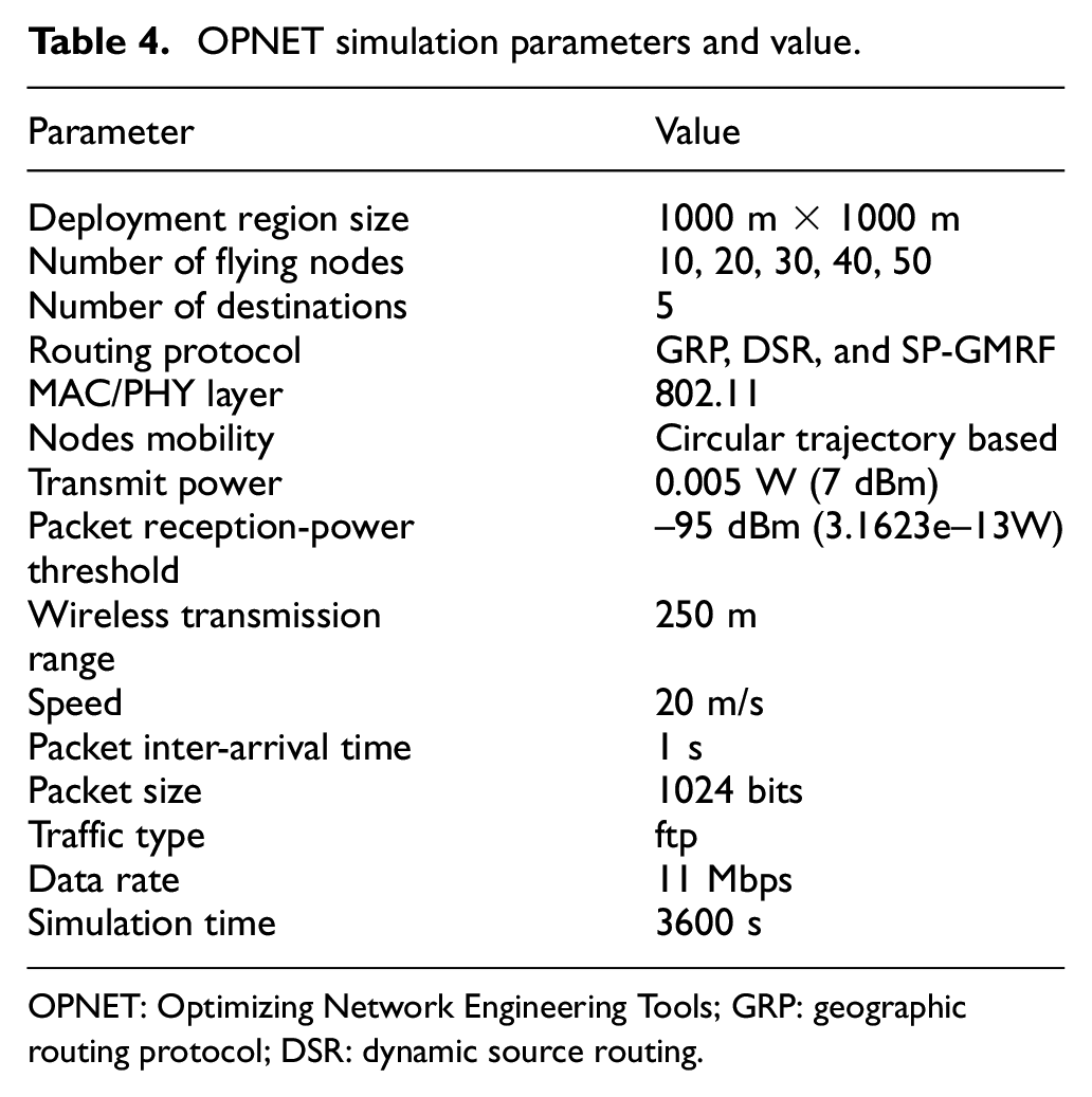
OPNET: Optimizing Network Engineering Tools; GRP: geographic routing protocol; DSR: dynamic source routing.
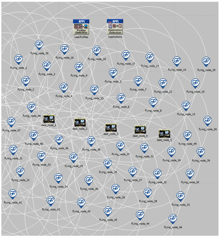
Sample deployment region with 50 flying nodes and 5 destinations.
We evaluate the performance and behavior of SP-GMRF as compared to GRP and DSR routing protocols in relation to the effect of changing the number of nodes for the ftp application. The assessment is made based on the performance metrics such as routing traffic sent/received, network load, delay, and throughput. Our performance metrics are plotted as a function of simulation time so as to capture their behavior during course of simulation. For each metrics, the performance of each protocol is evaluated while increasing the number of deployed nodes from 10 to 20, 30, 40, and 50. For each protocol and the corresponding metrics and number of deployed nodes, we repeat the simulation 10 times through generating 10 different seeds using the OPNET’s pseudo-random number generator and hence, 10 independent results are generated. Then, the evaluation results are averaged and the confidence intervals are determined for each metrics and corresponding number of deployed nodes. In order to help us establish statistical significance of the differences, we present the evaluation results with 95% confidence intervals. Detail statistical information regarding the performance result of each routing protocol is shown in Table 5.
Performance comparison result of the routing protocols.
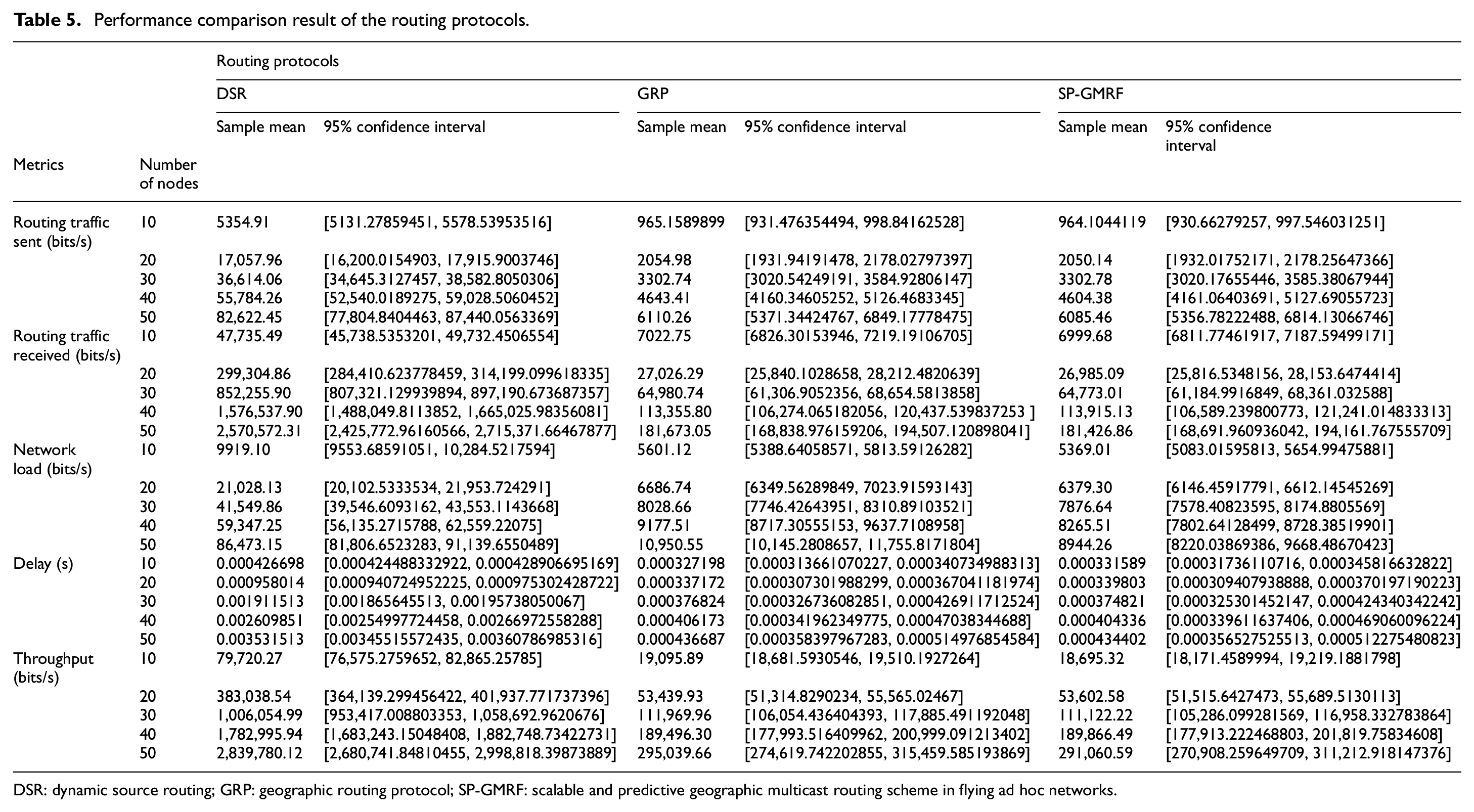
DSR: dynamic source routing; GRP: geographic routing protocol; SP-GMRF: scalable and predictive geographic multicast routing scheme in flying ad hoc networks.
Routing traffic sent and received
These metrics refer to the amount of routing traffic sent and received (in bits/s) in the whole network. The average routing traffic sent and received by each of the routing protocols with respect to different numbers of nodes (i.e. 10, 20, 30, 40, and 50 nodes) is shown in Figure 12(a)–(c). In all the protocols, the increase in traffic sent and received is observed with the increase in number of nodes. As seen from Table 5 and Figure 12, DSR has the maximum number of routing traffic followed by GRP and SP-GMRF. The SP-GMRF scheme has shown the least routing traffic overhead as compared to both DSR and GRP.

Routing traffic sent and received in (a) DSR, (b) GRP, and (c) SP-GMRF.
Network load
Network load refers to the total load (in bits/s) submitted to all WLAN layers by all higher layers in all deployed nodes of the network. The network load experienced by each of the routing protocols while increasing the number of nodes is shown in Figure 13(a) and (b). As depicted from Table 5 and Figure 13(a), when the number of nodes is 10, the average network load of DSR, GRP, and SP-GMRF is 9919.10, 5601.12, and 5369.01 bits/s, respectively. Similarly, as indicated in Table 5 and Figure 13(b), when the number of nodes is 40, the average network load of DSR, GRP, and SP-GMRF is about 59,347.25, 9177.51, and 8265.51 bits/s, respectively. In both simulation scenarios, DSR shows the highest network load followed by GRP and SP-GMRF. GRP and SP-GMRF perform better by exhibiting lower network load values as compared to DSR. SP-GMRF performs the best as compared to GRP and DSR. The better performance of GRP and SP-GMRF is resulted from efficient bandwidth consumption and reduced control message overhead, which is one of the peculiar characteristic of geographic-based routing approaches.

Network load in DSR, GRP, and SP-GMRF when number of nodes is (a) 10 and (b) 40.
Delay
Delay denotes the end-to-end delay (in seconds) of all the packets that are received by the WLAN MAC layer of all the deployed nodes in the network and then forwarded to the higher layer. The network delay encountered by each of the routing protocols as with the changes in number of nodes is shown in Figure 14(a)–(c). When the number of nodes increases, the average delay values of GRP and SP-GMRF in relation to the change in number of nodes are almost the same (i.e. about 0.000376 s) and the delay values go to constant as time increases. As seen from Table 5 and Figure 14, the delay for GRP is 0.000327, 0.000337, 0.000377, 0.000406, and 0.000437 s, and for SP-GMRF is 0.000331, 0.000339, 0.000374, 0.000404, and 0.000434 s while that of DSR is 0.000426, 0.000958, 0.001911, 0.002609, and 0.003531 s when the number of nodes is 10, 20, 30, 40, and 50, respectively. As compared to GRP and SP-GMRF, the DSR protocol has shown maximum increase in network delay with respect to the increase in number of nodes (see Figure 14(a)). The delay in DSR is due to the fact that to get routing information, every node in the network spends a lot of time while processing control messages received from the network nodes. This, in turn, results in higher routing path establishment delay of DSR as compared to other protocols. From this, we can deduce that GRP and SP-GMRF experience minimum network delay (i.e. better performance) than the DSR routing protocol.

Delay (in seconds) in (a) DSR, (b) GRP, and (c) SP-GMRF.
Throughput
Throughput denotes the total number of bits (bits/s) forwarded from WLAN layers of all the deployed nodes in the network to the higher layers. The throughput value of each routing protocol with respect to the changing number of nodes is shown in Figure 15(a)–(c). As shown in Table 5 and Figure 15, the throughput of DSR is 79,720.27, 383,038.54, 1,006,054.99, 1,782,995.94, and 2,839,780.12 bits/s; GRP is 19,095.89, 53,439.93, 111,969.96, 189,496.30, and 295,039.66 bits/s; and SP-GMRF is 18,695.32, 53,602.58, 111,122.22, 189,866.49, and 291,060.59 bits/s when the number of nodes is 10, 20, 30, 40, and 50, respectively. This shows that the DSR protocol has the highest throughput result in all the node scenarios as compared to GRP and SP-GMRF. Thus, with regard to the throughput aspect, the DSR protocol has shown better performance than the GRP and SP-GMRF schemes.
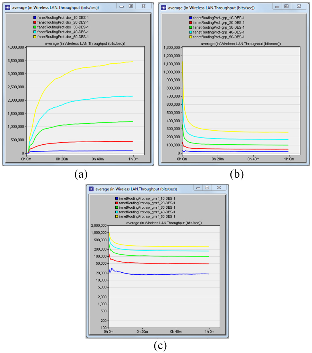
Throughput in (a) DSR, (b) GRP, and (c) SP-GMRF.
SP-GMRF instance application scenarios
In this section, we describe the possibility of integrating the SP-GMRF scheme in the IoT platforms using instance application scenarios. So as to give IoT services in different application scenarios, flying nodes can be armored with cameras (e.g. to take quality images from the air), data storage (e.g. to serve as data mule), sensors (e.g. for environmental monitoring like temperature, humidity, wind speed, and level of air pollution), GPS units and other embedded devices like wireless communication transceivers, flight controller, and on-board processing units. Two example scenarios where the SP-GMRF scheme can be integrated in the IoT platform are mentioned as follows. First, in scenarios where groups of flying nodes are supposed to accomplish a target mission such as patrolling a specific region, flying nodes equipped with IoT devices can use multicast transmission in an ad hoc communication environment. Second, in scenarios where flying nodes with remotely controllable IoT devices are supposed to take video images of a particular region such as earthquake hit region, the ground controller station (GCS), in an ad hoc fashion, sends multicast control messages to turn on the digital cameras of flying nodes in that region to record video images of the disaster or damage. As shown in Figure 16, in order to take the video images on the targeted region, the GCS disseminates multicast control messages to turn on the digital cameras of the destination flying nodes (in this case UAVs 2, 3, 4, and 5) that reside near the targeted region.

Instance application scenario of SP-GMRF.
Conclusion
A FANETs is a wireless ad hoc network specifically designed for the communication of UAVs or drones. We have reviewed the state-of-the-art in wireless multicast routing protocols and presented a SP-GMRF. We have described the data structure as well as the working logic of SP-GMRF algorithm using instance deployment scenarios. The MATLAB-based evaluation result of SP-GMRF has revealed that in cases of uniform as well as random distribution scenarios, when the communication range of nodes increases, the number of predicted one-hop neighbors to reach multicast destinations has also increased. When the transmission range is less than 500, the probability of getting predicted one-hop forwarders to reach multicast destinations is higher in uniform distribution approach than the random distribution approach. When it is greater than 500, the average number of predicted one-hop neighbors computed in the random approach is greater than the uniform approach. Concerning the computation cost, the larger the number of the predicted one-hop nodes is the higher the cost incurred at the source node while making computation for selecting the appropriate predicted nodes from among predicted one-hop neighbors nearest to multicast destinations. However, our scheme constructs efficient multicast routes with reduced transmission links.
The implementation of SP-GMRF is done using OPNET Modeler and we add the SP-GMRF as a new routing scheme in the MANET routing protocol groups of the OPNET Modeler. Then, the performance of SP-GMRF is compared with two of the existing MANET routing protocols (GRP and DSR). Evaluation of these protocols is done based on ftp (high load) application traffic and analyzing routing traffic sent and received, the network load, delay, and throughput during the simulation time while varying the number of deployed flying nodes in different simulation scenarios. The evaluation result has revealed that (a) the SP-GMRF shows the least routing traffic overhead and network load as compared to DSR and GRP, (b) the DSR protocol has the highest throughput performance than both GRP and SP-GMRF, (c) the DSR protocol has shown maximum network load and delay as compared to GRP and SP-GMRF, and (d) GRP and SP-GMRF have shown similarity in network delay, which is the least delay as compared to DSR. Finally, we have described two instance scenarios regarding the possibility of integrating the SP-GMRF scheme in the IoT platform.
Footnotes
Handling Editor: Andrey Koucheryavy
Declaration of conflicting interests
The author(s) declared no potential conflicts of interest with respect to the research, authorship, and/or publication of this article.
Funding
The author(s) disclosed receipt of the following financial support for the research, authorship, and/or publication of this article: This research work was supported in part by the Unmanned Vehicles Advanced Core Technology Research and Development Program through the National Research Foundation of Korea and in part by the Unmanned Vehicle Advanced Research Center (UVARC) through the Ministry of Science and ICT, South Korea, under Grant NRF-2016 M1B3A1A02937507 and 2017M1B3A2A01049996.