
Abstract
Corrosion monitoring is highly needed in concrete–steel civil engineering applications. By the corrosion information captured from structures, field experts can deduce where the corrosion events occur and how they will possibly evolve. However, traditional approaches are either based on high-cost manual operations or unable to support user’s control once the data collection starts. This article presents a corrosion-monitoring framework, called CoCoMo, based on embedded sensing and wireless networking technologies, aimed at achieving long-term and controllable corrosion monitoring. CoCoMo involves corrosion-detecting devices, well-designed wireless networking protocols, and the visual user interface which not only displays collected corrosion data but also serves as command-issuing agent. We finally build a small-scale test-bed to evaluate the feasibility and the transmission reliability of CoCoMo.
Keywords
Introduction
Corrosion of the reinforcing steel is one of the most significant factors severely degrading the durability of reinforced concrete (RC) structures, especially in marine climate or in the de-icing salt environments (widely existing in inland regions in winters).1–3 The statistics of the World Corrosion Recognition (WCR) indicate that the net economic losses caused by the worldwide corrosion are more than 2.2 trillion US dollars each year. 4 More serious is that the corrosion has led to heavy casualties. The explosion accident of China Petroleum & Chemical Corporation at Qingdao, China, in 2013, due to the corrosion of pipeline, caused 46 deaths and left 136 injured. 5 Corrosion events in RC structures always grow up silently and gradually; therefore, they are often neglected until some observable, critical point is reached due to the long-term corrosion accumulation. In practice, the online corrosion information of RC structures is highly needed in structure health evaluation (or safety assessment) and decision-making for maintenance and reinforcement. So far, the corrosion monitoring of RC structures mainly depends on manual operation, thereby consuming high labor costs and resulting in delayed reports of catastrophe sometimes.
Recently, there has been increasing attention to identify and evaluate the corrosion and its impact on the service quality of civil structures.6–11 Several corrosion-sensing approaches based on smart sensors and wireless networking technologies12–14 have been proposed in structure health monitoring applications.15–18 However, the corrosion detection in RC structure still faces practical challenges that make it hard to deploy a friendly and efficient system of monitoring real-world corrosions of RC structures.19–21
First, the existing widely used corrosion-monitoring approaches depend heavily on manual and intrusive operations, which not only demand extremely high human resources but also are unable to provide real-time information to end users or field experts. Although regular inspections with long interval of time can reduce the labor cost, they might miss the critical points indicating the ensuing damages and losses. In addition, the inspections of low frequency are only able to produce sparse samples of corrosion status, which might be insufficient for field experts to well understand the corrosion events and model their possible evolution.
Second, some recent works have attempted to leverage sensornets (wireless sensor networks) to monitor corrosions, aimed at reducing labor cost and achieving real-time monitoring; however, these designs mainly focus on data collection, without taking into account the two-way control in their systems, that is, the end user cannot proactively control the networked sensors and dynamically re-configure their sampling frequency or period at run-time. In practice, dynamically tuning the sampling rates according to the in situ corrosion status is very important and necessary to save the energy resource of wireless systems. For instance, shortly after an infrastructure is deployed, no obvious corrosion will occur and then a very low sampling frequency would be enough. Additionally, if a critical event (such as the extreme climate or the overloaded traffic passing by a bridge) occurs to a structure, the end users certainly expect that they be capable of booting up the sensors and increasing their sampling frequency to obtain larger amount of real-time data.
It is, therefore, very urgent to develop more intelligent and controllable monitoring systems, such that the corrosion information in need can be accurately detected, efficiently collected on demand, and timely transported to the end users. In this article, we design the CoCoMo framework (Controllable Corrosion Monitoring) to support the automatic, long-term, and user-controllable corrosion monitoring. CoCoMo uses commercial wireless sensing platform and well-designed protocols to achieve real-time and long-term corrosion monitoring, almost without human intervention. Especially, CoCoMo includes a virtual (software-based) user–network interface, which provides end users with the opportunity of controlling the monitoring networks: they can configure the sensing device at run-time, such as the sampling frequency and the start–stop period, without depending on any hardware.
The rest of this article is organized as follows. Section “Designs of CoCoMo” presents the detailed designs and practical considerations of CoCoMo. Section “Evaluations” evaluates CoCoMo in terms of availability and efficiency through test-bed experiments. Finally, this article is concluded in section “Conclusion.”
Designs of CoCoMo
Overview
Figure 1 shows the architecture of CoCoMo, which consists of three major components: the sensing platform of acquiring corrosion data, the front-end wireless network for corrosion data delivery, and the back-end system, by which end users or domain experts can not only access the real-time corrosion data but also issue instructions to tune the sampling rate with desirable granularity. The CoCoMo sensing platform integrates the commercial off-the-shelf wireless smart sensing mote with a built-in micro-controller, a wireless communication module, and external interfaces that can connect with the corrosion-detecting device and the power unit. The computing ability of CoCoMo platform allows pre-configured software codes both to automatically capture corrosion signals and to understand commands issued by end users. On the other hand, the wireless interface of CoCoMo platform makes it possible for the corrosion data to be timely delivered to end users through wireless medium, thereby being relaxed from wire connections that limit the geographical scale of monitoring and increase the deployment and maintenance costs.
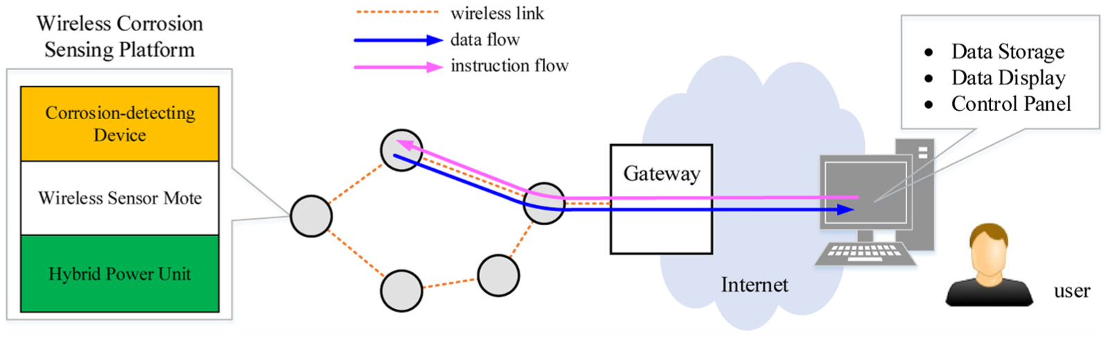
Architecture of the CoCoMo framework.
In CoCoMo, a set of sensors form the front-end wireless sensor network, which runs with low-power and low-rate radio channels. This sensor network is self-organizable, that is, it does not need human interventions even if new sensors are added or current sensors are removed in the future. We use a gateway to bridge the front-end corrosion-monitoring wireless sensor network and the back-end system (end users). Any communication-compatible device can serve as a gateway. Different from the work 22 that connects the wireless sensor network with the IP network via complicated protocols, CoCoMo does not carry heavy and diverse sensing tasks, and it only uses the gateway to complete the data and command switching between front-end sensor network and the end user, thereby significantly decreasing the cost of system maintenance.
The back-end system of CoCoMo, which can communicate with the gateway via wire or wireless connection, mainly involves a software-defined panel that can be deployed in a PC or other mobile devices with sufficient computing capability. This panel is designed to implement both the corrosion data visualization and the instruction (command) dissemination. So the end users can observe the corrosion signals and reset the sampling rate as desired at run-time, and what they need to do is only connecting their panel-running device with the gateway via Internet or LANs. CoCoMo decouples the back-end user and the front-end corrosion sensors by leveraging a virtual control panel. The idea of CoCoMo not only alleviates the development burden of control hardware—fully allowing engineers to concentrate on designing more functional applications—but also offers end users the system mobility.
To implement the proposed CoCoMo framework, we first introduce a corrosion-detecting device prototype which is used to simulate the corrosion process, with high fidelity, in steel–concrete structures. Second, we design wireless networking schemes to reliably transmit corrosion data and user-specific commands over the wireless sensor network. Finally, we propose the LabVIEW-based panel designs which allow end users to check their data and to issue commands anytime and anywhere.
Corrosion-sensing platform
Corrosion-detecting device
Technically speaking, the corrosion in RC structures is an electrochemical process. Figure 2(a) shows the packed prototype of the proposed corrosion-sensing device. Our corrosion sensor is mainly used to detect the corrosion status of reinforcing steel in concrete beams, and it is composed of three major components: the reference electrode (RE), the counter electrode (CE), and the working electrode (WE). The materials of the CE and WE are the graphite rod and the Q235 carbon steel, respectively. In Figure 2(a), CE, RE, and one of the three WEs are integrated to serve as a classical three-electrode system which can execute the galvanostatic step measurement. The other two identical WEs and RE are applied to obtain the electrochemical noise (EN) data. The sampling frequency of EN is usually set to be 2 Hz. The detailed working principle behind could be referred to Qiao and colleagues.23,24 In the design of the CoCoMo corrosion-detecting device, we novelly adopt cylinder-shaped electrodes, in order to achieving a better trade-off between the size of the device package and the surface contacting with the RC structure.

Hardware platforms of corrosion sensing and data collecting in CoCoMo: (a) corrosion-detecting device, (b) Telosb mote, and (c) gateway.
Smart wireless sensing platform
In CoCoMo, we use Telosb sensor mote as the corrosion-sensing platform. Typical for a commercial off-the-shelf sensor, Telosb is widely used in wireless sensor network applications, because it amalgamates wireless communication and computation in a single chip of low cost. In addition, Telosb is very rich in digital and serial peripheral interfaces, with which external sensing devices can be easily connected, if necessary. To achieve better resource efficiency on this Telosb-based platform, we adopt TinyOS operating system and nesC language to implement CoCoMo’s networking and control protocols. TinyOS and nesC are designed especially for energy-constrained wireless embedded systems, providing concurrent and event-driven programming models and flexible networking interfaces. 25 Of course, CoCoMo can also be totally implemented with traditional C codes. Therefore, we implement CoCoMo’s networking and control protocols with TinyOS codes. It is noticeable, here, that our designs are platform-independent, that is, the designs can be implanted to other platforms, with only needing to re-configure the low-level modules such that they can be identified by the new platforms.
Figure 2(b) illustrates the homemade Telosb sensing mote (we re-designed and re-implemented it, according to the open-source Telosb’s schema, in order to achieve longer radio range). The Telosb mote is driven by connecting its USB interface with either a power source (2 AA batteries) or any other standard USB power output. Figure 2(c) shows the gateway device used in the proposed CoCoMo prototype; the gateway is also called the sink, which bridges the front-end wireless sensor network and the end user—delivering the gathered corrosion data to end users and disseminating the end user’s commands over the wireless sensor network. The CoCoMo prototype uses a commercial development board, nanoPC-T1 4412, to implement the gateway functions. In the CoCoMo prototype, the nanoPC-T1 4412 board integrates a Telosb mote and directly connects with the Internet, so this presented gateway can communicate both with the front-end wireless sensor network and with the end users who can access the Internet—bridging the gap between the end users and the sensors caused by different communication mediums and standards. Despite the low cost, the nanoPC-T1 4412 renders another benefit: it has high computation capacity and several heterogeneous wireless communication interfaces, covering WiFi, GSM, and Bluetooth; in other words, we are offered a powerful mobile hand-held gateway available to end users.
Wireless networking infrastructure
With the ability of wireless communication, CoCoMo sensors can form a wireless network. The CoCoMo’s front-end wireless sensor network runs at 2.4 GHz with IEEE 802.15.4-compatible channel. Such wireless channels consume less energy in comparison with IEEE 802.11 (WiFi) and GSM, while providing sufficient data rates (250 kbps at most) for most monitoring-oriented applications. However, the lossy and dynamic nature of IEEE 802.15.4 links makes it very hard to always deliver sensory data reliably, especially when the data flows and the command flows co-exist in network simultaneously. Failed packet transmissions, lost over unreliable radio channels or dropped off due to buffer overflow, significantly waste the sensor mote’s resources of energy and bandwidth. To overcome this challenge, we propose a two-way communication network structure and then design a reliable transmission policy, in order to realize reliable data collection and command dissemination in CoCoMo system.
Two-way communication network structure
Different from the ZigBee network which also resides above the IEEE 802.15.4 standard, CoCoMo can self-organize involved sensors into a wireless network, neither with complicated pre-configuration in network initialization nor with any subsequent human intervention in network operation. In particular, considering the scalability and the energy efficiency, we design a protocol that establishes a tree structure over all CoCoMo sensors. In such a tree, sensors always transmit their data along the shortest path, the path with the minimum hops to the gateway where corrosion data are stored and made to wait for further analysis and processing. Noticeably, the CoCoMo prototype specifies the identical transmit power for all the sensor motes and then their communication ranges can be approximately reckoned to be the same. Consequently, less hops means lower demand on network energy resource.
After being deployed, the sensor motes communicate with their neighbors, to form themselves into an initial network topology, as shown in Figure 3(a). For two sensors A and C, A is C’s neighbor (or C is A’s neighbor) if and only if both of them can communicate with each other; in other words, if two sensor motes are neighboring, there exists a two-directional link connecting both of them. By hand-shaking in neighborhood, in general, each sensor mote can find out all its neighbors during the network initialization of CoCoMo. Since redundant sensors can be deployed in practice, we can reasonably treat the initial topology of CoCoMo to be a connected undirected graph, like the graph structure given by Figure 3(a), where the edge between two sensors represents the corresponding communication link. In other words, in the CoCoMo network, there always exits at least one path connecting a given sensor to the gateway. CoCoMo constructs a tree-like routing structure that can support two-way transportation over the sensor network—transporting corrosion data from sensors up to the gateway and transporting the control commands from the gateway down to all the sensors. Figure 3(b) demonstrates the CoCoMo’s tree-like routing structure and Algorithm 1 depicts how to establish this routing tree.

Organization of the CoCoMo network topology: (a) initial topology and (b) tree-like routing.
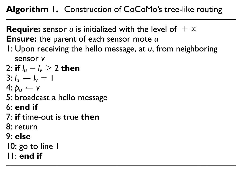
Before running Algorithm 1, all the motes other than the gateway maintain a level number that is initially set to be infinity, while the level of the gateway is set to be 0. Subsequently, the gateway broadcasts a hello message to find all its possible neighboring motes. Such a hello message contains the ID and the level number of the sender. When a sensor mote, say u, receives a hello message from sensor mote v, u will immediately know whether the level of v, denoted by
After the routing tree construction is completed, the data flow and the command flow can both be delivered over this tree. As to the command issued by end users, it can be transported reversely along the data path, thereby reducing the maintenance cost of the CoCoMo network. It is worthy to note that in practice, the command-issuing rate is far lower than the data sampling rate, and consequently, the command and the data will compete the same link or path with a very small probability. Specially, for the corrosion-monitoring application, the field experts usually first configure the network and then perform corrosion data acquisition. Therefore, the command issuing and the data collecting are temporally alternate—not conflicting—in most cases.
One major motivation of constructing a minimum-hop transport structure is to minimize the energy consumption of CoCoMo sensors and weaken the co-channel interference. Once the transmit power is specified, the energy consumption for a sensor to transmit one data packet over one hop can then be determined: the minimum-hop transportation is therefore the most energy-efficient choice for the data and the command delivery. What is more, the tree structure is very easy to maintain—each sensor mote only needs to know its parent. Even in the case with move-in or move-out sensor motes, only a limited number of broadcasts in neighborhood is needed when some sensor mote loses its parent or needs a new parent. For the scenarios with relatively high sampling rates, the proposed CoCoMo networking policy is still helpful. In such cases, we can budget the energy consumption based on varied transmit power. In reality, the energy consumed to transmit a packet is proportional to
Reliable transmission policy
In wireless sensor networks, the low-power, low-rate link is dynamic even in short terms, that is, it is not always reliable in data transmission. The CoCoMo system is deployed around a bridge or a building, and such scenarios will possibly impair the radio communication due to unexpected obstacles or absorptions of radio wave energy. One critical task of CoCoMo is to address the problem of low good-put caused by unreliable wireless communication. Like all the traditional approaches to handling unreliable data transmission, CoCoMo will retransmit the data packet dropped by the lossy link. However, the prominent feature of CoCoMo is that the sender will not immediately start a retry when a data packet is dropped, but will wait until the outgoing link turns better in quality, in order to save the energy consumed by meaningless retries.
Before giving out the retransmission policy, we first introduce the link model used in CoCoMo which is shown in Figure 4. In the real-world wireless applications, two communicating terminals (motes) often use the hand-shaking mechanism to ensure the completion of one packet transmission. In Figure 4, to obtain the link quality, A sends a series of probes to B. If B receives a probe, it will immediately reply an ACK message to A. By doing so, A can estimate the two-way quality of link
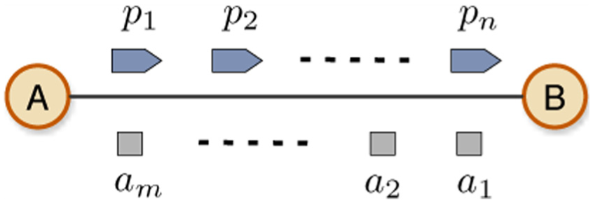
Illustration of the link model in CoCoMo where
To estimate the quality of the link between sending node u and receiving node v, CoCoMo uses two dynamic smoothing methods of determining the link quality and the interval time of sending probes, respectively. In CoCoMo, u will send n probes, one by one, with a period of time

In contrast to the traditional probing scheme with identical interval time, CoCoMo probes the link with a dynamically adjustable interval time, in order to guarantee that the maximum possible p will not tend to be infinity if the wireless communication environment cannot turn better for a long duration. Equation (2) gives the method of dynamically adjusting the probing intervals. In detail, if u finds that


Example of dynamically adjustable probing interval.
Virtual user-controllable panel
Through the LabVIEW-based virtual panel, users can observe the corrosion information and issue instructions (commands) down to the CoCoMo sensors. So far, only two commands are considered in CoCoMo: the start–stop of sampling task and the adjustment of sampling rate. Technically, the user can issue any commands once they can be packed according to the data format specified in advance. In the future, we will design richer commands for CoCoMo to extend the functions of user interface.
Panel’s user interface
The LabVIEW-based virtual panel 26 can run on all kinds of platforms including Microsoft Windows, various distributions of UNIX/Linux, and Mac OS. With LabVIEW, users can not only access the real-time corrosion data but also issue instructions anytime and anywhere on PC or tablet. The basic entity of the resulting program is the virtual instrument (VI) that consists of executable code controlled via a graphical front panel on the screen similar to a real instrument. Also, it provides an easy-to-use graphical environment that permits users to easily process the collected corrosion data, using complex data-processing algorithms, without the detailed knowledge of the underneath data-acquisition system.
The CoCoMo front-end panel, as shown in Figure 6, can connect to the Internet automatically once being launched. Every CoCoMo sensor can have its own panel to present data and can be operated separately. Just one step is required to operate the CoCoMo system: click button ①. The voltage and current values will be shown on the left and right sides separately. Each of the two values is displayed in two regions: the real-time value (② and ③) and the time-varying data wave (④). The real-time value would flash quickly to indicate the arrival of raw data. The data wave aims at providing users with the line graph, simulating a real oscilloscope. The different corrosion data types, active or passive, can be classified by the panel and shown in separate tab pages (⑤) which can be switched if needed. Besides the multi-dimensional display, the CoCoMo panel stores all the received raw corrosion data into a log text file. If users want to stop some sensor, what they need to do is just click the start–stop button in the panel corresponding to that specified sensor.
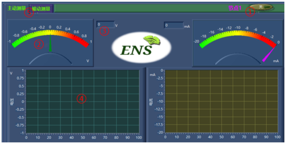
LabVIEW-based UI panel in CoCoMo.
Data format in CoCoMo’s panel
All the corrosion data received are packed according to the data format specified in Table 1. The head and the foot of a packet, both of which are 1 byte of length, are filled with “0×56” and “0×AA,” respectively. According to the head and the foot bytes, we can easily resolve a packet from the packet stream. The node ID is the CoCoMo sensor ID which is defined when the node is initially deployed. The type field indicates the data type: “0×00” represents the passive-test data and “0×01” the active-test one.
Data format of CoCoMo’s panel.

The in-packet values that represent the voltage and the current of corrosion should be transformed into values of engineering units, according to equations (3) and (4), respectively, where v and c are the non-dimensional values involved in packet, and V and C are the conversed values with the units of volt and ampere. If CoCoMo is implemented with other platform and sensors, of course, equations (3) and (4) should be updated as the new datasheet declares


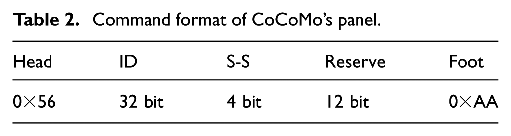
The command for sensors can also be realized by operating buttons in the CoCoMo panel: clicking the start–stop button will let the panel send a “start/stop” command to the sensor. The format of such command message, also in raw byte stream, is shown in Table 2. The packet contains 8 bytes which begins with “0×56” and ends with “0×AA.” The Start or Stop field (abbreviated as “S-S”) consists of a 4-bit sub-field (“0×1” represents the start and “0×2” the stop); the Reserve field, including 12 bits filled with “0×000,” by default, is reserved for future use.
Command format of CoCoMo’s panel.
Evaluations
To evaluate CoCoMo, we conduct a small-scale experiment based on concrete beams and the proposed corrosion-detecting devices, which are shown in Figure 7. The concrete beams are exposed in outdoor environment, and each corrosion-detecting device connects with a wireless sensing mote; and all the sensing motes are organized into a wireless network that delivers the corrosion data (represented by the voltage and the current measurements) to the end user who can check these data and issue commands through the virtual LabVIEW panels. In experiments, the network consists of only four sensing motes due to the constrained cost of deployment. But we believe that it can, in some degree, reflect the real-world applications in terms of wireless transport, corrosion detecting, and systematic availability as a whole. Specifically, each sensing mote in experiments is driven by two AA batteries. In the future, we will re-implement CoCoMo with energy-harvesting sensing platform, thereby reducing the dependency on the energy supply of battery. In fact, however, CoCoMo is energy-efficient through carefully configuring the wireless protocols concerning the idle listening which duty-cycles the network and then the sensing mote enters into active state only when needed.

Test-bed of RC beams and the corrosion-sensing device before being embedded in the beams.
Figure 8 plots the electrochemical emission spectroscopy (EES) data—also called the pitting corrosion’s fingerprint—which are collected by CoCoMo. According to the EES data, the corrosion status with and without aggressive chloride ion (Cl−) can be clearly and accurately identified. The typical pitting corrosion features of RC structures are successfully and thoroughly revealed. The amplitudes of the electrochemical potential noise without and with pitting corrosion events are positive tens of millivolts and negative hundreds of millivolts in Figure 8(a) and (c), respectively. According to the ASTM C876091 code, the corrosion status can be qualitatively confirmed. Furthermore, the details of the electrochemical current noise without and with pitting corrosion are distinctly reflected in Figure 8(b) and (d), respectively (where the unit of current noise is µA/cm2). Even the transient current peaks released during the nucleation process of the corrosion pit are successfully and clearly embodied in Figure 8(d). According to these current noise data, the pitting corrosion damage can be further quantitatively recognized using the three-dimensional (3D) cellular automata algorithm. Considering the scope of this article, we do not further discuss the specific electrochemical meaning of these EES data here. Briefly, the corrosion status under the passive and active circumstances can be directly and accurately determined based on the electrochemical current noise. These electrochemical essence data in Figure 8 are very significant and valuable for the early warning, damage evaluation, safety assessment, life-circle design, and maintenance and reinforcement of RC structures. Besides, this controllable framework for the wireless corrosion monitoring paves the solid way to realize the intelligent infrastructures in civil engineering.

Corrosion data distribution: (a) potential without CI−, (b) current without CI−, (c) potential with CI−, and (d) current with CI−.
CoCoMo serves as a general framework of monitoring the corrosion and configuring the monitoring parameters at run-time, and it depends heavily on the wireless communication infrastructure. We evaluate the CoCoMo prototype in terms of two-way throughput in a 24-h experiment. Table 3 shows the results, where “
Two-way throughput of each path.

Conclusion
This study has presented a general wireless corrosion-monitoring framework, called CoCoMo, which involves the novel corrosion-detecting device and well-designed wireless protocols to guarantee the networking performance. CoCoMo supports not only the real-time, automatic data collection, but also the dynamically controllable scheme that can adjust the monitoring parameters at run-time. One significant feature of CoCoMo is that it decouples the front-end sensing system and the end users: they can adopt different corrosion-detecting devices and different ways of interacting with the front-end sensing system. In other words, CoCoMo releases the burden of the end users who have to manually manage or re-program the corrosion-sensing process. In addition, the tree routing structure and the reliable transmission control of CoCoMo are platform-independent and easy to deploy, thereby being suitable for any front-end corrosion-monitoring systems using low-power wireless mediums. In the future, we will develop more function-rich virtual user interface based on the LabVIEW environment and investigate more flexible and reliable interaction patterns for end users.
Footnotes
Academic Editor: Carlos Calafate
Declaration of conflicting interests
The author(s) declared no potential conflicts of interest with respect to the research, authorship, and/or publication of this article.
Funding
The author(s) disclosed receipt of the following financial support for the research, authorship, and/or publication of this article: The authors were supported, in part, by the Fundamental Research Funds for the Central Universities of China with grant no. 2017ZY20 and the NSF of China with grant no. 61300180.