
Abstract
Sensor node localization is a crucial aspect of many location-related applications that utilize wireless sensor networks. Among the many studies in the literature, multidimensional scaling-based localization techniques have been proven to be efficient, obtaining high accuracy with lower information requirements. However, when applied to large-scale wireless sensor networks with coverage holes, which are common in many scenarios, such as underground mines, the transmission path can become deviated, degrading the localization performance of this type of connectivity-based technique. Furthermore, in such complex wireless environments, non-line-of-sight reference objects, the presence of obstacles and signal fluctuations change the communication range and make it difficult to obtain an accurate position. In this article, we present a anchor-free localization scheme for large-scale wireless sensor networks called the ranging and multidimensional scaling–based localization scheme. We use ranging and non-line-of-sight error mitigation techniques to estimate accurate distances between each node pair and attempt to find inflection nodes using a novel flooding protocol to correct transmission paths that have become deviated by a coverage hole. Moreover, we replace the singular value decomposition with an iterative maximum gradient descent method to reduce the computational complexity. The results of the simulations and experiments show that our scheme performs well on wireless sensor networks with different coverage holes and is robust to varying network densities.
Keywords
Introduction
Localization techniques for wireless sensor networks (WSNs) have attracted increasingly more attention due to their wide application for emergency response, intelligent transportation systems, target tracking, and so on.1,2 It is essential for the sensor nodes to be able to automatically discover their locations in many WSN applications. In practice, it is infeasible to obtain the position of each node with manual configurations or positioning equipment such as global positioning system (GPS). Instead, localization protocols usually require some anchor nodes whose locations are known in advance, and the other nodes can localize themselves by calculating the relative locations between themselves and the anchor nodes by measuring the physical distances using ranging hardware. 3
In large-scale WSNs with hundreds or even thousands of nodes, which are typically highly resource constrained, it is important to find a relatively simple and energy-preserving method for performing network localization. 4 Multidimensional scaling (MDS), a technique from mathematical psychology, is used to calculate the positions of all the nodes in a network given only basic connectivity information.5–7 With the proposed MDS-MAP 5 localization method, the algorithm can detect the shortest paths between each node pair with simply the given network connectivity information. The algorithm roughly estimates the distance between each pair of nodes and normalizes the resulting coordinates considering the anchor nodes, whose positions are known. This localization scheme first calculates the hop counts between the anchor nodes and a node. Then, the Euclidean distance of two nodes can be approximated through the hop counts multiplied by the average physical hop distance. After obtaining the Euclidean distance, it is easy to locate nodes through a simple calculation. Because of its simplicity, there has been growing interest in localization methods based on connectivity of the network.
The problems facing MDS-MAP lie in the fact that connectivity-based (CB) and constant-anchor (CA) algorithms use only connectivity information to perform localization without any ranging techniques. To improve accuracy, the MDS technique can be extended to full network localization using the measurements of range differences (related to the time of arrival (TOA)) and range difference rates (related to the frequency difference of arrival (FDOA)).8–10 In these works, an accurate relative distance instead of communication range between two nodes is used to perform localization. Obviously, adding the extra information of the distance can be expected to yield smaller errors, especially in non-line-of-sight (NLOS) scenarios, where classical MDS algorithms are very sensitive to poor and dynamic transmission environments. 11 However, in certain application scenarios, such as underground mines and indoors, the complexity of such environments often severely affects localization accuracy. Complications include NLOS reference objects, the presence of obstacles, signal fluctuations or noise, and changes in an environment.12,13 It can be easily determined that it is very important and difficult for wireless signal propagation parameter estimation to obtain an accurate position due to the complex signal transmission patterns characterizing such environments. Therefore, with traditional ranging-based localization methods, the performance will be degraded in such environments.
Furthermore, in ordinary cases, most WSNs have to be deployed randomly with the help of aircraft, such as helicopters, which can hardly guarantee a high coverage quality of the networks. 14 Moreover, for an already-deployed WSN, the sensor nodes can be easily destroyed due to environmental factors such as wind, obstacles, or vibration. Therefore, the coverage hole problem of WSNs is unavoidable and has a negative effect on the performance of CB localization schemes. Obviously, the paths between different nodes around the coverage holes are highly bent rather than being straight lines. The bent distance calculated using the hop counts multiplied by the average physical hop distance strongly deviates from the true Euclidean distance, which leads to large localization errors.
In this article, we present an anchor-free localization scheme, named the Ranging and MDS-based localization scheme (RMDS). We assume that all the nodes in a network with coverage holes can measure the physical distances from their nearby nodes using time-of-flight (TOF) ranging with certain hardware, which is practical in state-of-the-art WSN node hardware architectures.12,15 To address the above-mentioned problems, we attempt to estimate the degree of curvature around the coverage hole and use it to correct the distances between the node pairs whose communication paths will be bent around the hole. To achieve this, we perform a coverage-aware and link-correlation-balanced flooding (CLF) mechanism to detect the boundary of the hole. Moreover, we embed the TOF ranging in the flooding process and propose an NLOS elimination method based on an adaptive Kalman algorithm to improve the accuracy of the one-hop-measured distance results obtained by refraction and reflection of radio signals in complex wireless environments. Finally, we can obtain a more accurate result of the distance matrix consisting of the smallest distances between every pair of nodes and then calculate the position of each node with an improved MDS algorithm. In summary, our contributions are two-fold.
We propose an efficient and energy-aware flooding mechanism based on link correlation and group one-hop neighbors into clusters to prevent the ACK explosion problem. Then, we estimate the subtree size and inflection degree of each node and detect the inflection nodes.
We combine the TOF ranging and NLOS error mitigation technique with the MDS algorithm to estimate the real Euclidean distance between the node pairs whose transmission paths are modified by the coverage hole. With this method, a more accurate distance matrix consisting of the shortest distances between every pair of nodes can be obtained to improve the localization accuracy.
It is worth noting that although only one coverage hole is considered in this article, our proposed scheme is also efficient in a network with multiple coverage holes. In fact, in a large-scale and dense WSN application, there may exist more than one coverage hole. If there are several adjacent small holes, we can compute the convex hull of all the wireless nodes and consider it as a big one. If the multiple coverage holes are far from each other, we can divide the network into several parts, that each one contains one hole in it. Thus, multiple-hole scenario can be always converted into one-hole scenario, and our scheme is also applicable. It should also be feasible to design the scheme for network with multiple holes without combining into one big hole. How to design the scheme considering each individual hole is left as the future work.
The remainder of this article is organized as follows: Related work is surveyed in the next section. An overview of the RMDS is given in the third part. Then, the fourth section introduces some important auxiliary nodes used. The next two sections describe the RMDS in detail. The seventh section presents simulation results, and the final part concludes the article.
Related work
Overview of localization techniques
Localization has been extensively researched in many studies on WSNs.16–19 Current localization approaches can be divided into many groups, including connectivity-only-based, range-based, and range-free approaches. These localization algorithms provide some effective solutions, and we will briefly review such work in the following.
The centroid-based approach proposed by Bulusu et al. 20 is one of the earliest works on CB localization. One node estimates its relative position simply by calculating the centroid of several anchors’ positions. In the distance vector (DV)-hop, 21 at least three anchors are selected, and each node will measure the number of hops to the anchors. Then, the node’s location can be obtained by triangulation. Render Path (REP) is another typical localization technique that only utilizes connectivity information. 22 The algorithm includes a method that uses geometric features to correct the estimated length of a path when a coverage hole exists in the network. REP detects the boundaries of the holes and labels the boundary nodes. It then creates a virtual hole at the corner where the path has deviated from the shortest path. The virtual hole induces a new shortest path based on the geometric information. Combining the original path and the new shortest path, REP can determine the real Euclidean distance between the two nodes. The algorithm depends on the full and exact boundary of the network; however, it is nearly impossible to obtain such a boundary. In addition, the real Euclidean distance is approximated by the hop count of the new shortest path multiplied by the average hop distance. This concept may lead to large localization errors because of the bent shortest path.
MDS-based localization
The MDS technique is also often used for node localization in WSNs because of its simplicity and applicability to large-scale networks. In traditional MDS-based schemes, only connectivity information is needed. Every pair of nodes will count the number of hops between them; then, a distance matrix can be built and is taken as an input to calculate the relative coordinates of each node in a centralized manner.5,7,23
However, the connectivity information is very limited, and the distance calculated using hop numbers multiplied by communication range is inaccurate, especially in complex wireless environments such as underground mines and indoors. In such environments, wireless links exhibit asymmetry and irregularity and can be easily affected by multipath and reflection.24,25 Therefore, directly applying traditional MDS-based algorithms in such environments will lead to large errors. Thus, some researchers have attempted to combine ranging techniques with the MDS localization method. The classical ranging-based MDS algorithm assumes that the distance between any two nodes is measurable or calculable so that nodes can be located through matrix operations on the distance matrix. In practice, distances exceeding the range of communication cannot be measured. Therefore, obtaining distances beyond the range remains a problem.
Some modified MDS algorithms have achieved various results through some indirect methods for calculating and correcting distances. Wang et al. 26 proposed an MDS-based localization method with multipath mitigation for passive ultra-high-frequency band (UHF) radio frequency identification (RFID) systems. They attempted to measure the distance between two nodes and eliminate the multipath error to improve the localization accuracy of the MDS method. MDS-DMC (MDS-Distance matrix) has been investigated as a range-based algorithm in Popescu and Hedley. 27 When there is a coverage hole in the network and when boundary nodes cannot be found around holes, this will lead to some distances being missed in the matrix, eventually resulting in localization failure. Y Wang et al. 28 proposed a localization scheme for large-scale sensor networks with complex shapes and possibly with holes. The scheme first selects landmarks on network boundaries with a certain density and then constructs a landmark diagram and its dual combinatorial Delaunay complex on these landmarks. This scheme faces a challenge with respect to networks with holes: determining the correct network layout. In addition, when the node number is large, this algorithm for configuring the network runs very slowly, and if the node range is in a non-convex area or an inner ring, an illegal triangle is produced. Similarly, landmark and edge nodes are also used in the connectivity-based and anchor-free three-dimensional localization (CATL) scheme, 29 which performs well in both two-dimensional (2D) and three-dimensional (3D) spaces with coverage holes. However, due to the iterative procedure, CATL suffers from error propagation and thus cannot be used in complex wireless environments.
When a coverage hole exists in the wireless network, the communication paths between different nodes will always overlap with the holes, thus deviating from the ordinary paths and becoming bent paths. Obviously, the bent paths will deviate greatly at the hole boundary, which makes the communication distances larger than their Euclidean distances, as illustrated in Figure 1. In the example, there exists a triangular coverage hole in the WSN area. The three vertices of the hole are expressed as black dots, which are called inflection nodes (for simplicity, the ordinary nodes are omitted, and we assume that a sufficient number of nodes are placed in the area). Moreover, the dotted lines represent the data transmission of message flows from one node to another node (it is worth noting that Figure 1 is just a sketch to show the concept of inflection node and its connection to the coverage hole). It can be easily determined that the message flow will be performed in a near straight-line manner when the hole is not present. However, with the existence of the coverage hole, the message flows will be bent at the inflection nodes, and obviously, the transmission times of inflection nodes will be greater than those of other nodes. Therefore, we select two types of auxiliary nodes, named boundary nodes and landmark nodes, to collect the number of message flows. Both auxiliary nodes are real and not virtual. After the auxiliary nodes are selected, the landmarks will start to flood messages across the entire network to form a tree architecture. To avoid the ACK explosion problem and reduce energy consumption, we propose a coverage-aware and link-correlation-based mechanism in this article to perform an efficient flooding process. Obviously, in Figure 1, the data packets passed around the hole will be forced to deviate to the inflection nodes, resulting in a large-scale subtree.

Example of message flow crossing the inflection nodes.
Thus, in this article, we attempt to calculate the scale of each node’s subtree to detect the inflection nodes and modify the distance between two nodes whose communication path contains the inflection nodes. To the best of our knowledge, this is the first research on combining ranging techniques and the MDS algorithm that also considers complex wireless environments.
It is worth noting that the performance of our proposed algorithm will degrade when the coverage hole is located at the edge of the network, as the inflection nodes will be selected inappropriately, especially on the junction of coverage hole and the network boundary. This will affect the bent length estimation and the final localization result. But note that the case when the coverage hole is at the edge of the network rarely happens and how to deal with this kind of scenario is left as the future work, which we are currently working on.
Key ideas of RMDS
In this section, we present an overview of the RMDS, including the key ideas of the RMDS and the main procedures.
When using the MDS method to calculate the positions of all nodes, it is crucial to obtain an accurate distance matrix that consists of the shortest paths between each pair of nodes. However, as mentioned above, when coverage holes exist in the network, the paths between different nodes around coverage holes will deviate from straight lines, thus producing large errors if we treat the bent paths as ordinary paths and use hop counts multiplied by the average physical hop distance to calculate their lengths. Thus, the heart of RMDS is a method for identifying the inflection nodes and correcting the lengths of bent paths in the distance matrix. As described above, the inflection nodes are nodes near or at the network corners, where transmission paths are bent and deviate from their straight-line course. They are critical for identifying coverage holes and calculating the lengths of bent paths.
Obviously, every single node and its multi-hop neighbors in a wireless network will form a tree architecture, and every node in the tree has its array of subtree sizes. It can be easily determined that if the network has no holes, nodes at the same depth in the tree have approximately the same subtree sizes for any hops. However, this rule will be violated in a network with holes or boundaries. Messages that flow in a nearly straight-line manner will deviate and be forced to travel via the inflection nodes, which contributes to creating a fatter subtree. In other words, an inflection node is more likely to have a large subtree. For example, in Figure 1, more messages flow along the dotted line crossing the inflection nodes than along other nodes, which will produce a fatter subtree in the tree architecture. Based on the statistics of each node in these trees created by boundary nodes, every node can compare its subtree sizes with some standards, and the inflection degree of each node will increase with the subtree sizes over the standards. If a node finds that its own inflection degree is higher than a certain threshold, it will be taken as an inflection node. There are many paths between any two nodes in these trees, and thus, we select the path with the minimum number of hops as the shortest path.
In a large-scale WSN, the energy consumption and ACK explosion problem of traditional flooding protocols30,31 are unacceptable. In the RMDS, we propose a high-efficiency and energy-aware flooding mechanism to estimate the subtree size and inflection degree of each node. The flooding protocol is based on link correlations for grouping one-hop neighbors into clusters and electing cluster heads for aggregate ACKs to prevent the ACK explosion problem. By collecting the aggregate ACKs from each cluster head, the sender calculates its real-time probability of achieved reliability, which is relatively poor in complex wireless environments. Then, the sender node can decide which node will rebroadcast and how many times to retransmit the message based on the real-time probability and opportunistically. In addition, a comprehensive consideration of rapid coverage and balanced energy that allocates different priorities to one-hop neighbors can suppress the transmission of nodes that have less residual energy and fewer non-covered neighbors. Thus, we can detect the size of the subtree and inflection degree of each node to determine the positions of coverage holes and inflection nodes. In addition, by embedding the TOF ranging into the message transmission of the flooding protocol, we can easily measure the one-hop distance between two nodes. In addition, to improve the ranging accuracy in complex wireless environments, such as underground mines and indoors, we propose an adaptive Kalman filter algorithm with colored measurement noise to eliminate NLOS errors, which we have proven to be non-Gaussian-distributed noise. 12 Finally, we can correct the distance between the node pairs whose transmission paths are bent around the coverage hole using the inflection degree, and thus, the MDS localization process is able to be performed successfully.
Auxiliary nodes
In the following, we will present the meanings and methods for selecting two types of auxiliary network nodes, called network boundary nodes and network landmark nodes, which exist in the wireless networks and are not virtual nodes. The purpose of the two types of nodes is to assist the flooding process for identifying inflection nodes and the shortest paths.
Boundary nodes
Boundary nodes involve a set of nodes on or close to the edge of a network. Nodes broadcast messages, and each node that receives a message will respond with an ACK. With the flooding protocol, every node can obtain its one-hop neighbors. In addition, the information is exchanged between nodes so that every node is able to learn the number of nodes within its two-hop distance. Then, each node exchanges its number of two-hop neighbors and can compare with the average degree. If the number of neighbors is substantially smaller than the average degree, the node marks itself as a boundary node. It is worth noting that the boundary nodes should not be identical to the network boundary. Under certain rough conditions, they may not cover the entire network edge; sometimes, they will only approximately cover, and not exactly, the network boundary. We do not want to look for full or exact boundaries, as they are not required by our algorithm. These boundary nodes merely help us select some nodes for flooding and thus do not need to be full or exact in any sense. Figure 2(a) shows the original network with a hole, and Figure 2(b) shows the selected boundary nodes.
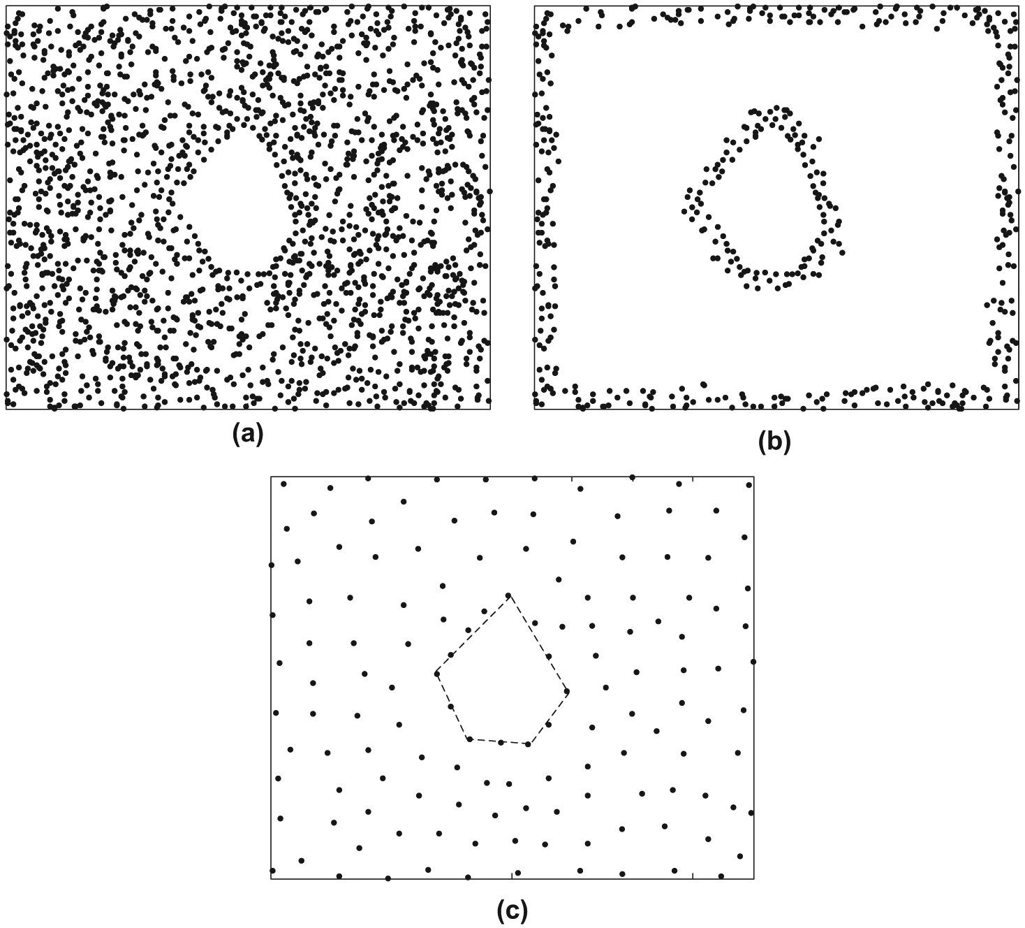
An example of boundary and landmark nodes. (a) Original network with a coverage hole. (b) Boundary nodes in the network. (c) Landmark nodes in the network.
Landmark nodes
The landmark nodes are nodes uniformly sampled from the original network with a density controlled by a small parameter
Procedure of the RMDS
In the following, we describe the main steps of the RMDS.
Select two types of auxiliary nodes to assist in flooding.
Calculate the subtree size and inflection degree using an efficient flooding protocol and identify the inflection nodes.
Perform TOF ranging, NLOS mitigation, and MDS localization.
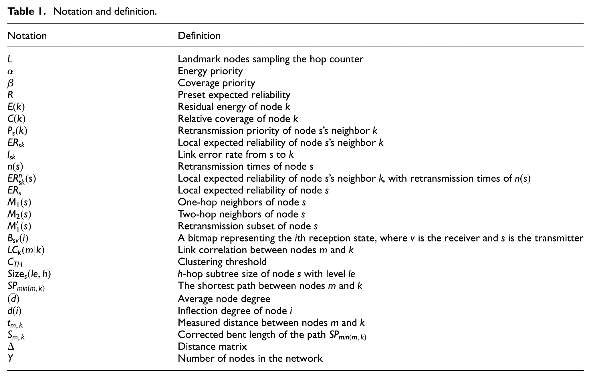
We assume that there is a coordinator for the network that controls the flooding process and the whole localization process. There are some notations and symbols used to describe the RMDS algorithm, which are listed in Table 1 for ease of reference.
Notation and definition.
Network structure and detection of shortest paths
In this section, every boundary landmark will flood the network to detect inflection nodes that are described in subsection “MDS-based localization” of section “Related work” and the shortest path between any two nodes. Before this action, we have to cluster the neighbors of nodes with an effective flooding.
Coverage-aware and link-CLF mechanism
In large-scale networks with frequent flooding, the energy consumption of nodes cannot be ignored. These large numbers of floods expend energy rapidly, leading to nodes with less residual energy. To reduce the energy consumption of flooding, we divide the one-hop neighbors into clusters. Nodes within a cluster reply with fewer ACKs during flooding. Meanwhile, to guarantee the performance of the flooding, it is usually assumed that there is no packet loss during data transmission. However, in the above-mentioned complex wireless environment, this assumption is no longer valid. 31
Calculating retransmission priorities
First, a node that will broadcast a message (or rebroadcast a received message) will calculate the priorities of all neighbors. Suppose that the sender is

where
This CLF mechanism suffers from two issues in determining the retransmission priority when a packet loss occurs. One issue is the residual energy of all one-hop neighbors, which makes each node maintain a one-hop neighbor table to record the real-time residual energy of neighbors. The other issue is determining the one-hop neighbors’ relative coverage, which refers to the number of one-hop neighbors’ uncovered neighbors by the packet from the sender. The information updates of the multi-hop neighbor tables are as follows.
Detecting the residual energy of all neighbors. Each node monitors its residual energy in real time and informs its neighbors by sending a periodic broadcast. A neighbor who receives this broadcast will update its local one-hop neighbor table corresponding to the sender’s index. Thus, the priority of nodes with low residual energy can be decreased in the next round of selecting retransmission nodes. For instance, in Figure 3, the black circles including
Determining the relative coverage. In Figure 3, except for the black nodes, which have already received the sender’s message, the remaining white circles represent the relative coverage of

Relative coverage and residual energy.
Local expected reliability
During the flooding process, it is important to ensure that every packet can be transmitted correctly. However, in a complex wireless environment, it is very difficult to achieve a 100% successful transmission rate.
32
Thus, we usually have an expected reliability (ER)
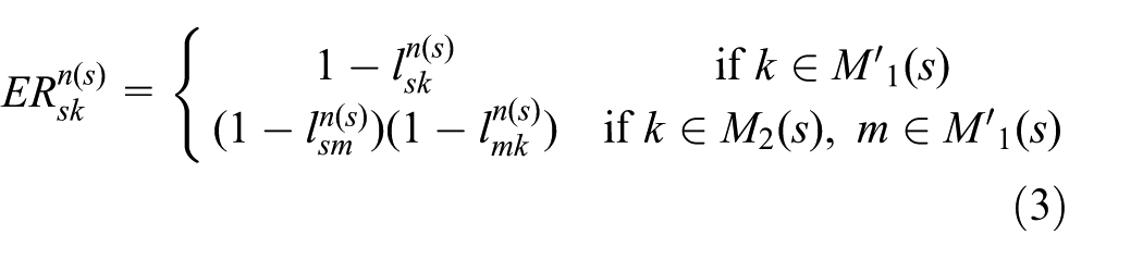
After allocating one-hop neighbors’ different priorities, the sender
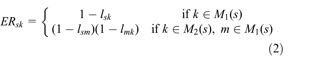
where
First,
Thus, overall, for the sender

Link correlation and clustering
To avoid the ACK explosion problem in the traditional flooding algorithm, we exploit link correlations in the clustering and aggregating ACK process to reduce the energy consumption during both data and ACK transmissions. Nodes that have similar link conditions are grouped into one cluster, and one ACK from the cluster head can acknowledge on behalf of all the nodes in the cluster. This effectively ameliorates the ACK explosion problem. First, we define the link correlation

where
For example, in Figure 4, a bitmap of “1101100111” from node

Example of calculating link correlation.
ACK aggregation
After the sender collects all the receivers’ bitmaps and link correlations, it begins to group neighbors into clusters and aggregate ACKs. As mentioned above, we choose the link error rate and the link correlation as the clustering metrics.
Although the bitmaps capture a distinguishing feature of link correlations, it seems unclear how to find a criterion for precisely dividing one-hop neighbors into clusters based on link correlation. Furthermore, the impact of such a criterion on the final clustering results is quite different between various circumstances. In CLF, we decide not to pursue an ideal and unique criterion. Instead, we use a very simple linear function while letting the clustering threshold change adaptively in response to the clustering process. As mentioned above, in a complex wireless environment, we usually have a preset ER
During the clustering process, the sender checks whether
Figure 5 shows an example of the clustering process based on link correlations, wherein five receivers are divided into two groups. Clearly, there is a strong link correlation between the link states represented by bitmaps within the nodes grouped in the same cluster. A single ACK from the cluster head can easily represent the acknowledgments for the memberships. Specifically, with a high link correlation, nodes within the same cluster have high probabilities to receive the same packet, and the reception at all these nodes can be acknowledged with one ACK. The node with the highest link error rate in each cluster will be selected as the cluster head to send the ACK. For instance, in Figure 5, nodes
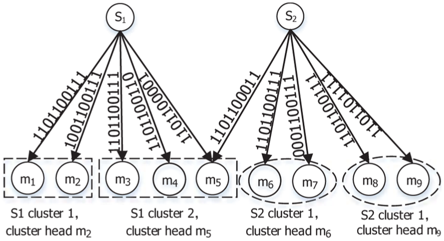
Example of the clustering process.
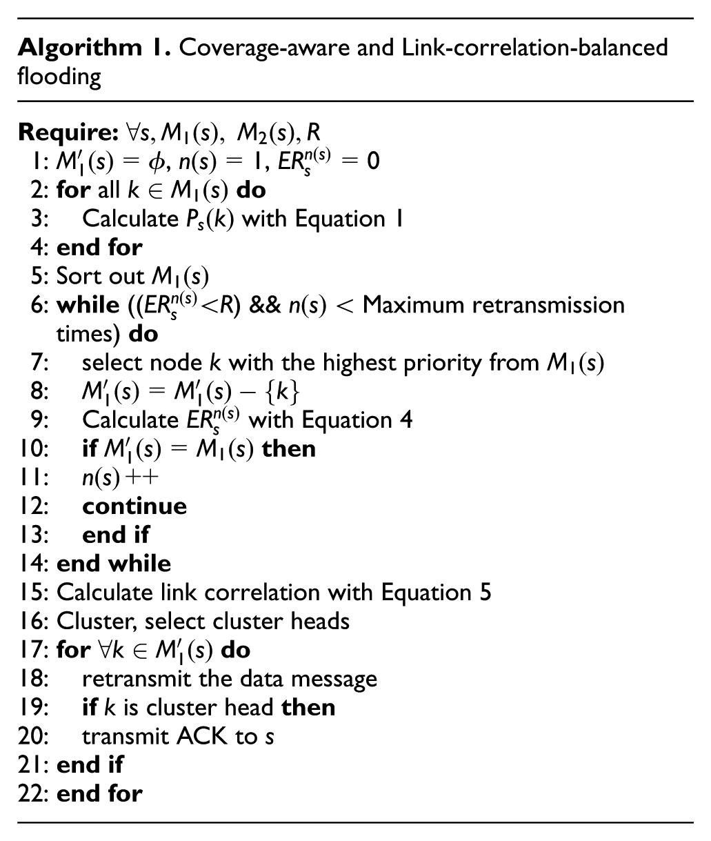
We summarize the coverage-aware and link-CLF mechanism in Algorithm 1.
Detecting inflection nodes
Now, we will describe how to detect the inflection nodes using the above-mentioned efficient flooding protocol. During this step, boundary landmarks flood the whole network using the coverage-aware and link-CLF mechanism, while the network coordinator both monitors the flooding process and records the total number
Leaf nodes begin to return reports to the tree. The reports contain an array of a node’s subtree sizes, defined as
It is clear that a node’s inflection degree is no greater than the number of flooding sources, that is,
Ranging between nodes and filtering
After detecting the inflection nodes, we can measure the distance between any two nodes and amend the distances of the node pairs whose transmission includes the inflection nodes, meaning that their path is bent around a coverage hole. TOF is a ranging method that utilizes the radio flight time between nodes to measure their distances. 33 Because a node is able to communicate with its one-hop neighbors directly, TOF ranging is feasible. Of course, TOF requires hardware support. A node performs TOF ranging with its one-hop neighbors and saves its measurements. In a harsh communication environment, these measurements always contain NLOS error, which mainly affects location accuracy. NLOS error adds a positive bias to measured range, which was modeled in different ways in the literature such as exponentially distributed, 34 uniformly distributed, 35 Gaussian distributed 36 and constant along a time window. 37 Typically, the model depends on the wireless propagation channel and the specific technology under consideration. 38 In our previous work, 12 we have proved that it is accurate to model this bias error with colored noise, which can be modeled by the sum of an accumulated error and zero-mean white Gaussian noise. Therefore, in this step, we use an NLOS mitigation algorithm based on the adaptive Kalman filter similar to the algorithm presented in Li et al. 12 The system equation and the observation equation of the Kalman filter can be given as follows


where

where


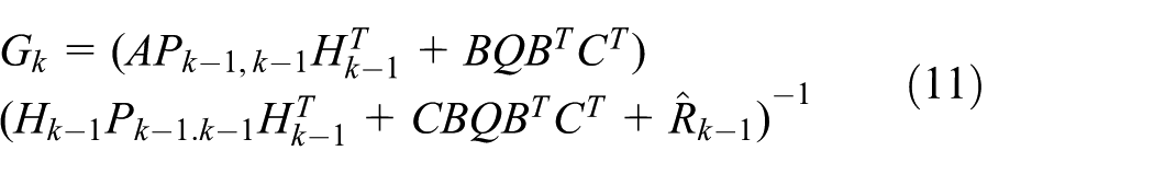

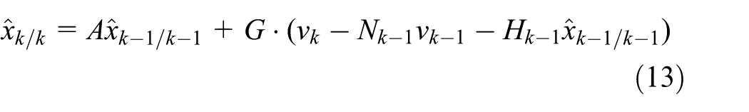
The process consisting of the above formulas is iterative, and the detailed derivation can be found in Li et al. 12 The output of the iteration is the distance required for localization. These optimized distances help us to calculate the smallest distances and localize nodes in the subsequent steps.
Bent length of path and distance matrix
In a network with coverage holes, there often exist two nodes whose distance cannot be measured directly due to indirect communication. In this case, the distance is usually calculated based on the sum of all measurable distances in the path. However, because of the existence of coverage holes and inflection nodes, the distances between node pairs whose transmission paths are bent around the hole obtained from such a sum will be very different from the true distances. From the description above, it is obvious that inflection degree can be used to measure how bent the path is. In Figure 6, we can determine that the greater the number of inflection nodes along the transmission path of one node pair, the curvier the path is, which means that the real distance will be much shorter than the result calculated using the sum of the measured distances between each hop in this path. To avoid errors and obtain an accurate distance matrix, we can correct the bent length for a one-hop distance along the shortest path
where


The shortest path deviated by a coverage hole.
MDS-based localization
After the distance matrices of all the nodes are calculated, we utilize the multidimensional scaling algorithm to calculate the relative coordinates. The heart of the algorithm is the use of the similarity between nodes to establish a mapping and then obtaining the distribution of nodes in the space. Usually, the core of the location calculation using the MDS algorithm is the distance matrix decomposition, which can be implemented using singular value decomposition (SVD).39,40 However, in a large-scale network, the computational complexity of SVD operations is high and will introduce errors into the final localization results. In this article, we replace the SVD with the iterative maximum gradient descent method to improve the localization accuracy while reducing the computational complexity.
Assume that the coordinate vector of all
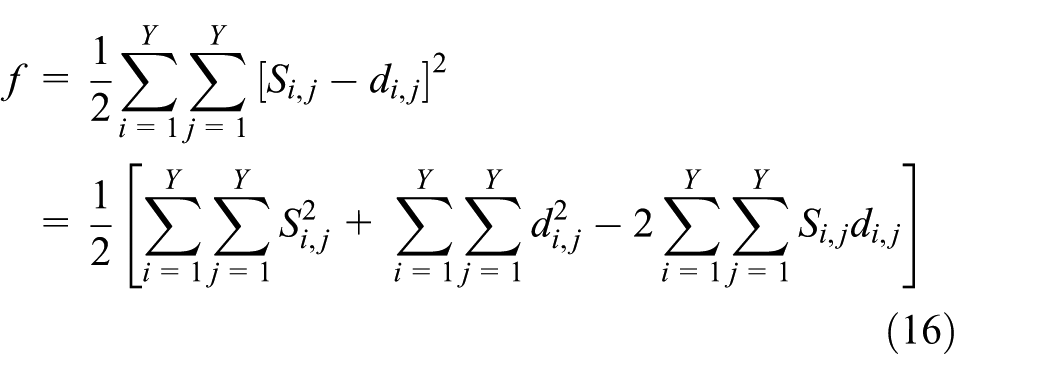
where
This can be converted into matrix form as follows

where

Obviously, the optimal coordinate vector
Simulation
To evaluate the performance of the proposed algorithms, we design simulations and compare with the other two localization methods. We deployed 1600 wireless sensor nodes in an area of
Parameter setting of the simulation.

Performance of CLF
First, we evaluate the performance of the proposed flooding mechanism. As mentioned before, in a complex wireless environment, it is very difficult to achieve the expected transmission reliability due to the relatively high link error rate and limited transmission times. Thus, during the experiments, we select two metrics: achieved reliability (network-wide)-to-target reliability ratio (ATR) and the number of transmitted packets (excluding ACK packets) per node (NTP). We compare with another classic flooding protocol called POFA, 30 which is also a probabilistic and opportunistic algorithm that considers the retransmission subset and real-time retransmission results. In the comparison, we chose 0.9 and 0.95 as the expected transmission reliabilities instead of 1, which is infeasible in most applications. Then, the performances of the two flooding schemes are evaluated under link error rates of 0.05, 0.1, and 0.15, which are common values in complex wireless environments. 32 Figures 7–9 present the performance of the algorithm in terms of the ATR and NTP. Clearly, the performance of CLF is as high as that of POFA in terms of reliability and the overhead of transmit packets (not including ACKs). Note that CLF effectively ameliorates the ACK explosion problem, conserves energy on ACKs, and balances the residual energy of sensor nodes in real applications. The fact that the network is steadier and that the lifetime is longer also indicates the effectiveness of the proposed strategy.
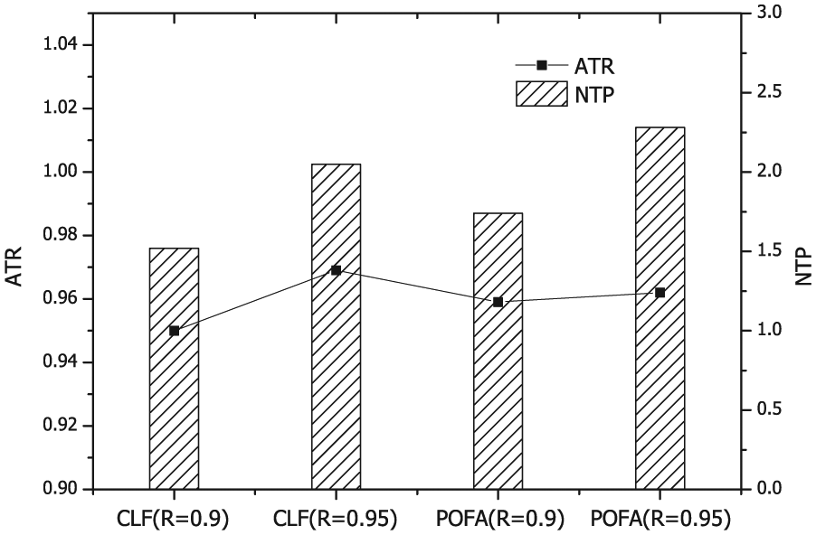
Performance of the flooding mechanism with a link error rate of 0.15.
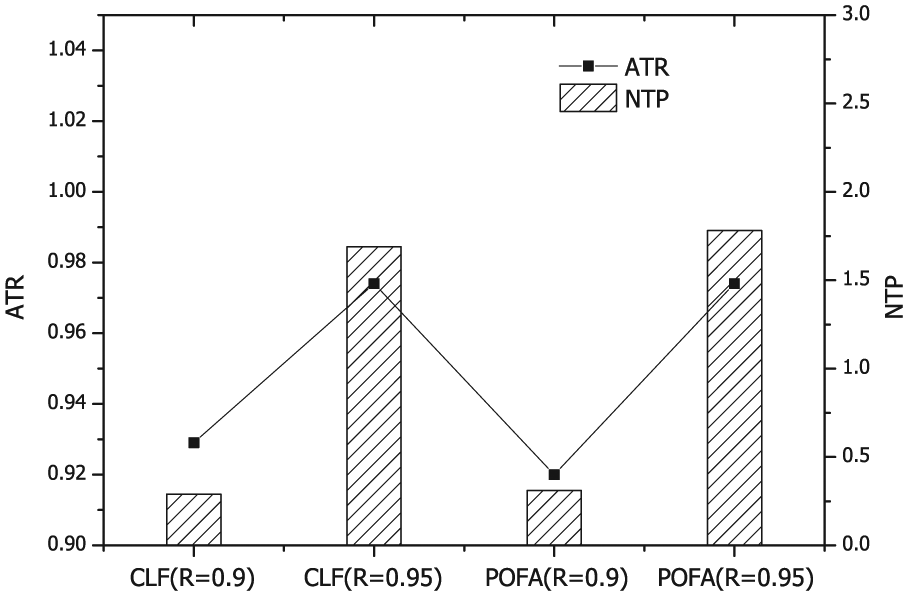
Performance of the flooding mechanism with a link error rate of 0.10.
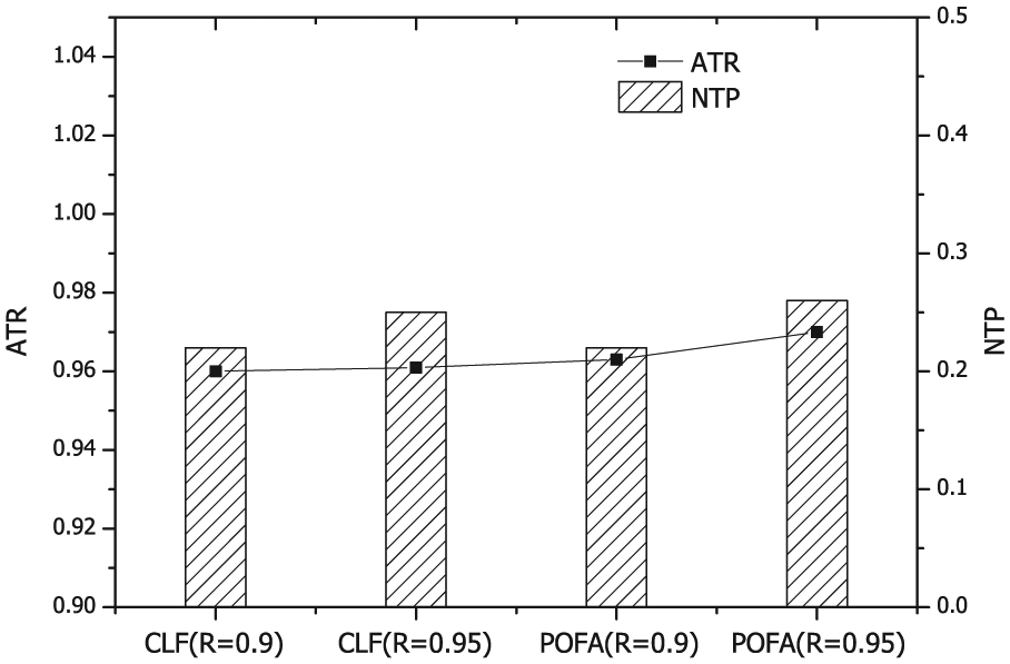
Performance of the flooding mechanism with a link error rate of 0.05.
In CLF, we take rapid coverage and balanced energy into account to allocate different priorities to one-hop neighbors and suppress the transmission of nodes that have less residual energy and fewer uncovered neighbors. With such design, we can maintain a balanced residual energy in the whole network area. We also do some experiments to show the results, as illustrated in Figures 10 and 11. In the evaluation, we set initial energy of each node is
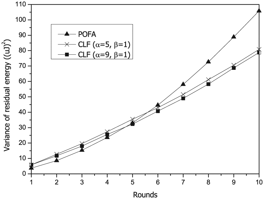
Variance of residual energy when link error rate is 0.05 and expected reliability is 0.95.

Variance of residual energy when link error rate is 0.1 and expected reliability is 0.9.
Figure 12 reveals that CLF saves more than 50% average number of ACK packets in most cases while achieving target reliability. When the link error rate is small (0.05), the ER of the senders with a single broadcasting and part of one-hop neighbors broadcasting can already make the ER greater than target reliability,

Average number of ACK packets.
Localization performance under different network topologies
We compare the RMDS against two 2D localization schemes from previous works. One scheme is the classic MDS-MAP scheme, 5 and the other scheme is REP, 22 which is also a CB localization scheme. In MDS-MAP, it just utilizes the network connectivity information and tries to estimate the distance between each two nodes with the hop counts. When applying MDS-MAP in a large-scale area with coverage holes, the communication path between nodes at the boundary of holes will deviate from the ordinary paths and become bent path. Obviously the bent path will deviate greatly at the hole boundary, which makes the estimated distance larger than their Euclidean distance, and yield great error to the localization result. In REP, it can also detect the coverage hole and amend the distance between two nodes locating at the boundary of the hole. However, it calculates the coordinates of each node in a triangulation manner with the assistance of three seeds. Our proposed scheme can calculate the distance between each two nodes, and then, all the coordinates can be obtained more precisely with decomposition of the distance matrix.
The localization accuracy is expressed quantitatively using the average localization error, defined as the average Euclidean distance between the obtained and true coordinates of all the nodes. To make the comparison meaningful, we calculate the absolute coordinates, achieved by setting the physical coordinates of five preselected nodes, and the other nodes can estimate their real positions using the relative coordinates to the preselected ones. The resulting network thus has the same scale and orientation as the original network.
In the simulations, we generate three types of node deployments with rectangular and triangular randomly generated size coverage holes, as illustrated in Figure 13(a), (c), and (e). The calculated node deployments are shown in Figure 13(b), (d), and (f). For the coverage holes with regular shape, that is, rectangular and triangular holes, the average localization error is 2.37 and 1.46 m, respectively. Compared with the network size, it suggests a very small distortion in the network layout. In contrast, MDS-MAP and REP perform poorly, with average errors of 3.37 and 2.69 m for rectangular hole, while 2.90 and 2.26 m for triangular hole. Regarding the coverage hole with randomly generated shape, RMDS also performs well, and the localization error is 3.12 m, while MDS-MAP and REP gain a error of 4.21 and 3.85 m. The error difference indicates that the RMDS can perform well in wireless networks with different coverage holes.

The network topology of the boundary and landmark nodes. (a) The original network with a rectangular hole and an average node degree of 12.2. (b) Network topology calculated by the RMDS, with an average localization error of 2.37 m. (c) The original network with a triangular hole and an average node degree of 13.8. (d) Network topology calculated by the RMDS, with an average localization error of 1.46 m. (e) The original network with a randomly generated shape hole and an average node degree of 11.4. (f) Network topology calculated by the RMDS, with an average localization error of 3.12 m.
Localization performance under different node densities
During the experiments, we also change the node density to demonstrate the performance of the RMDS by changing the communication range of each node with a small step size. Obviously, the larger the communication range is, the greater the average node degree is, resulting in a higher node density. The lowest average node degree is 8. For the two different types of network deployments, the localization performances of the different algorithms are illustrated in Figures 14 and 15. In Figures 14 and 15, the X-axis indicates the average connectivity of the whole network, and the Y-axis is the average localization error. It can be observed that the performance of our proposed algorithm is substantially better than its counterparts. In the network topology with the rectangular hole, the localization error decreases by 21.1% and 12.8% compared with MDS-MAP and REP, and the error decreases by 36.4% and 28.5% in the network with the triangular hole. Moreover, the localization error decreases with increasing network connectivity (density of node coverage).

Localization error with a rectangular hole.

Localization error with a triangular hole.
Finally, we calculate the cumulative probability density (CDF) of the three algorithms by calculating the percentage of nodes whose absolute localization error is no greater than a certain value (indicated by the X-axis). The results are illustrated in Figures 16 and 17. From the results, we can see that the RMDS produces good results and is quite robust to varying network densities.

CDF of localization error with a rectangular hole.

CDF of localization error with a triangular hole.
Conclusion
This article discusses the localization problem in large-scale WSNs with coverage holes in complex wireless environments, which is a very common scenario in underground mines or indoors. When applying the classic MDS-based localization algorithms in such situations, calculating the bent path distances between nodes using hop counts multiplied by the average physical hop distance will result in large deviations from the true Euclidean distance, which—in turn—will lead to a large localization error. In this article, we present a localization scheme called RMDS to tackle these problems that estimates the degree of curvature around a coverage hole and uses that to amend the distances between the node pairs whose communication paths are bent around the hole. To achieve this, we perform a coverage-aware and link-CLF mechanism to detect the boundary of the hole. Moreover, we embed the TOF ranging in the flooding process and propose a NLOS elimination method based on the adaptive Kalman algorithm to improve the accuracy of one-hop measured distance results affected by the refraction and reflection of radio waves in complex wireless environment. The simulation experiments show that the proposed algorithm outperforms its counterparts, works well in large-scale WSNs containing different coverage hole shapes, and is robust to varying network densities.
Footnotes
Academic Editor: Vicente Traver
Declaration of conflicting interests
The author(s) declared no potential conflicts of interest with respect to the research, authorship, and/or publication of this article.
Funding
The author(s) disclosed receipt of the following financial support for the research, authorship, and/or publication of this article: This research is supported in part by grants from the National Natural Science Foundation of China (61301114 and 51304058).