
Abstract
In the wireless communication market, Internet of Things is one of the major issues. Internet of Things is a technology which connects all objects to the Internet and enables to share the information of the objects with each other. Also, energy harvesting for batteryless devices is also one of the new issues in order to realize Internet of Things. Through the realization of Internet of Things, all objects can connect to the Internet and share own information with each other. Since the sensor communication with the low-power battery or without the battery is possible by the backscatter technique, a backscatter technique is highly useful for the realization of Internet of Things. This article proposes a scheme that a sensor is connected to the Internet and the optimal performance is obtained. For reliable backscatter technique for mobile user, this article proposes the two encoding schemes which are FM0 and Miller-n. Also, to minimize the loss of the data rate, these two encoding schemes are adaptively used according to mobility. The mobility is decided by signal-to-noise ratio and channel state. For mobile user, the proposed backscatter technique has high error performance due to proposed adaptive encoding scheme.
Keywords
Introduction
Internet of Things (IoT) is a technology which connects all objects to the Internet and enables to share the information of the objects with each other. Therefore, IoT has been studied widely and energy harvesting for batteryless devices is also one of the new issues in order to realize IoT. 1 For realization of IoT, a wireless sensor system like radio frequency identification (RFID) is widely used and variable techniques are applied.2–5 A wireless fidelity (Wi-Fi) backscatter system is one of the techniques which reflect signal to provide the Internet connectivity to the sensor system using a Wi-Fi signal and a backscatter technique. 6 The radio frequency-powered (RF-powered) device in the Wi-Fi backscatter system harvests the ambient Wi-Fi signals for batteryless transmission. A sensor in the Wi-Fi backscatter system is defined as a Wi-Fi sensor. In uplink communication of the backscatter system, a sensor receives the Wi-Fi signal from a Wi-Fi access point (AP) used as Wi-Fi helper transmitting the Wi-Fi signal and transmits the received signal to a Wi-Fi reader by reflection.7,8
However, the Wi-Fi backscatter system has the disadvantages of poor error performance by the limited power. Also, it has poor error performance for mobile users. For high reliability to mobile user, this article proposes the two encoding schemes. In the proposed encoding scheme, FM0 and Miller-n encoding are used. To obtain advantages of each encoding scheme, adaptive encoding is used to seek high reliability and high data rate in the mobile state. The performance for various cases is confirmed and is compared by simulation for error performance and throughput.
Wi-Fi backscatter system model
This section shows the simple system model of Wi-Fi backscatter communication that consists of a Wi-Fi AP, a Wi-Fi reader, and a Wi-Fi sensor in Figure 1. A Wi-Fi reader is a Wi-Fi device embedded in a smart phone and a Wi-Fi sensor is a RF-powered device as a tag. A Wi-Fi backscatter system has a communication process, which is as follows. First, a Wi-Fi AP broadcasts Wi-Fi packets to all devices. A Wi-Fi reader can read and transmit the packet information of the Wi-Fi AP, and the Wi-Fi backscatter communication from a Wi-Fi reader to a Wi-Fi sensor is defined to downlink communication. Generally, a Wi-Fi sensor uses the signal of the Wi-Fi AP to gather energy for power charge since a Wi-Fi sensor without a battery is mostly used. Also, a Wi-Fi sensor is just device that cannot decode the Wi-Fi packet from a Wi-Fi AP but can convey the information from a Wi-Fi AP. However, a Wi-Fi sensor can transmit the information of the Wi-Fi packet by the uplink communication of the proposed Wi-Fi sensor system and the uplink communication of the Wi-Fi backscatter system means Internet connectivity from a sensor to a reader.

Sensor system using the Wi-Fi backscatter communication.
In this article, the scheme obtaining optimal performance is proposed in uplink communication of Wi-Fi backscatter when a Wi-Fi reader is mobile or static. The process of uplink communication and the proposed scheme are described in the next section.
Proposed scheme
This article proposes the scheme obtaining optimal performance in uplink of Wi-Fi backscatter communication. The uplink communication means Internet connectivity from a Wi-Fi sensor to a Wi-Fi reader. A Wi-Fi sensor receives a Wi-Fi signal from a Wi-Fi AP and conveys the information “0” or “1” by the modulation of the received signal. The Wi-Fi signal is modulated to the information “0” when the Wi-Fi sensor absorbs the Wi-Fi signal. In contrast, the Wi-Fi signal is modulated to the information “1” when the Wi-Fi sensor reflects the Wi-Fi signal to the Wi-Fi reader. This modulation by the reflection is conducted using a low-power switch. The low-power switch uses the impedance and consumes less than 1 µW of power. 9 At this time, the sensor transmits the signal using the charged power by the signals of the Wi-Fi AP and the reader. The Wi-Fi signal is modulated by the sensor only when the sensor is queried from the reader.
The Wi-Fi reader decodes the signal reflected by the sensor after the transmission from the Wi-Fi AP. For the decoding at the reader, the reflected signal is analyzed through the simulation, and some features are represented as Figure 2. Figure 2 shows the amplitude of the signal when the Wi-Fi sensor transmits the modulated signal by the impedance modulation. Wi-Fi signal amplitude is represented according to each packet and means the average amplitude per packet meaning the information “0” or “1.” The modulated signal by the sensor has clear values as the binary modulation. Therefore, the Wi-Fi reader can decode the modulated signal using a simple threshold detector and the Internet connectivity between the sensor and the reader is possible. 6

Amplitude of the transmitted signal from the sensor.
In the conventional scheme in Kellogg et al., 6 the mobility of the reader is not considered. So, we propose a new scheme considering the mobility of the reader and applying the suitable encoding scheme. This article assumes that the reader is mobile when signal-to-noise ratio (SNR) and channel state are bad. Since the quality of the communication is different according to the mobility of reader, the adaptive encoding scheme is additionally applied. Also, only the mobility of the reader is considered because the reader is a mobile device embedding Wi-Fi and most sensors are fixed. The mobility is detected by the reader instead of the sensor because the sensor has very simple structure and cannot do complex processing. Figure 3 represents the communication process between the sensor and the reader in the scheme. The Wi-Fi reader transmits CTS-to-SELF to all devices CTS-to-SELF informs other Wi-Fi devices that the Wi-Fi reader keeps other Wi-Fi devices from transmitting the Wi-Fi signal while the Wi-Fi reader transmits the signal to the sensor.6,10 As a result, the sensor can communicate with the Wi-Fi reader without the interference by other Wi-Fi devices. The sensor retransmits the received signal to the reader using the backscatter technique. The reader measures SNR and a channel state between the sensor and the reader using the backscatter signal and detects the own mobility. Although the reader is not really mobile, the high encoding like Miller-4 is efficient since the reliability is improved in bad communication environment. In contrast, FM0 for data rate is efficient although the reader is not really static for the similar reason. It is expected that the reader is static when the SNR value is high and the channel state is good. In contrast, it is expected that the reader is mobile when the SNR value is relatively low and the channel state is relatively bad compared with the static reader. The channel state is represented as the amplitude of the channel in this article.

Communication process of the proposed scheme.
Figure 4 shows how the mobility of the reader is detected. The red lines mean the SNR value and the channel state when the reader is mobile. The blue lines mean the SNR value and the channel state when the reader is static. SNR and the channel amplitude are represented according to each packet having the information “1.” Through Figure 4, it is clearly confirmed that SNR and the channel amplitude of the mobile reader are lower than those of the static reader. Therefore, the mobility of the reader can be detected by the SNR value and the channel state.

SNR and the channel information for the mobility detection.
The encoding scheme is applied for more reliable communication. After the estimation for the mobility, the reader transmits the encoding information to the sensor. FM0, Miller-2, and Miller-4 are used as the encoding scheme of the sensor in the scheme. The FM0 encoding scheme has high data rate and the Miller-n encoding scheme has high reliability as n increases. 11 Since the error performance of the moving device is worse than that of the static device, the Miller encoding scheme is applied when the reader is mobile. In the next section, the performance of the Wi-Fi backscatter communication system according to the mobility of the reader and the encoding scheme is represented.
Performance evaluation
This section shows the simulation results for the schemes explained in the previous section. The simulation is based on orthogonal frequency division multiplexing (OFDM)12,13 used in the Wi-Fi system and the parameters are defined as follows. The fast Fourier transform (FFT) size is 64, the cyclic prefix (CP) size is 16, the modulation is quadrature phase shift keying, and the transmitted data by the sensor is 64 bits. The signals experience a 4-path Rayleigh fading.
In the proposed scheme, the SNR is estimated by calculating the ratio of instantaneous power of received signals and noise power. One of the methods for noise power estimation is calculation of the distance between received signals and modified preamble signals which are distorted by the channel gains. So, with closed-loop system, the estimated SNR can be used at the transmitter as a criterion of encoding scheme selection. However, for easy understanding, the feedback information about channel gains and noise power are given as follows. The relative SNR value having the value of zero and the channel amplitude having the value of one are used as the standard values for the static reader. In order to express the mobility of the reader, the relative SNR and the channel amplitude compared with the standard values are used in the simulation. In Figures 5 and 6, Static reader is the case that the SNR value is 0 and the channel amplitude is 1, Mobile reader 1 is the case that the SNR value is −10 dB and the channel amplitude is 0.8, and Mobile reader 2 is the case that the SNR value is −20 dB and the channel amplitude is 0.6. It means that SNR and the channel amplitude are low when the reader moves and Mobile reader 2 has the fastest mobility. FM0, Miller-2, and Miller-4 are used as the encoding scheme in each case.
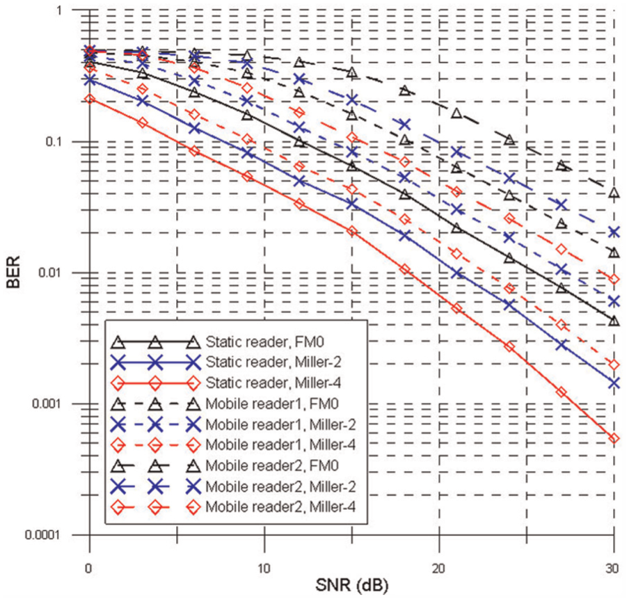
BER performance according to the mobility and the encoding scheme.

Throughput according to the mobility and the encoding scheme.
Figure 5 shows the bit error rate (BER) performance according to the mobility of the reader and the encoding scheme. In the static reader, three encoding schemes of FM0, Miller-2, and Miller-4 have good BER performance. In the mobile reader, however, it is confirmed that the BER performance is extremely degraded when the FM0 is used particularly. Figure 6 shows the throughput performance. FM0 has better throughput performance than Miller-2 and Miller-4 in all cases. In consideration of the simulation results, Mobile reader 2 uses Miller-4 for the BER performance, Mobile reader 1 uses Miller-2, and Static reader uses FM0 for the throughput performance. Therefore, the proposed scheme can obtain the optimal BER and throughput performance by the adaptive encoding scheme according to the mobility of the reader.
Conclusion
IoT is a technology which connects all objects to the Internet and enables things to share their information with each other. For realization of IoT, the sensor system like RFID is widely used. This article proposes the improved Wi-Fi backscatter system using the adaptive encoding scheme. Wi-Fi backscatter is a technique that the sensor can connect to the Internet. A sensor is a RF-powered device in this system. A backscatter technique is useful to the realization of IoT since the sensor can communicate with other devices and connect to Internet without the battery. The Internet connectivity from a sensor to a reader is possible by the uplink communication and the encoding scheme of the sensor is applied according to the mobility of the reader in the proposed scheme. The mobility of the reader is detected by this scheme and SNR and the channel state are used. The quality of the communication is degraded when the reader moves. When the reader is static, FM0 obtaining high data rate is used. In contrast, the Miller encoding scheme is used for the high reliability when the reader is mobile. Therefore, the optimal performance is obtained according to the mobility of the reader. And it is expected that the proposed scheme is usefully applied to IoT industry.
Footnotes
Declaration of conflicting interests
The author(s) declared no potential conflicts of interest with respect to the research, authorship, and/or publication of this article.
Funding
The author(s) disclosed receipt of the following financial support for the research, authorship, and/or publication of this article: This work was supported by Institute for Information & communications Technology Promotion (IITP) grant funded by the Korea government (MSIP) (No. B0126-15-1076, Development of non-powered technology combined with ambient RF energy harvesting and Backscatter data transfer).