
Abstract
The scope of a single regional indoor positioning network is often restricted to its main anchor communication range and more susceptible to obstacles. Multiple main anchors can be the basis of an indoor positioning network’s extensibility and can adapt to the complex communication environment. In this article, a novel TIME-DRIVEN opportunistic routing protocol with intelligent response is proposed. First, an extendable ultra-wideband positioning system is modeled. In two or more communication cells, anchors can act as a main or slave anchor in different areas, respectively, and a forward clock check package from the initial district to its surrounding area. They can also achieve the clock synchronization of the entire network. In this model, the anchors will be divided into different sizes of clusters, and the main anchor is elected according to the broadcast time. Furthermore, the relay anchor will be intelligently selected according to the opportunistic probability based on the received signal strength indicator. Finally, experiments are conducted to verify the performance of the method.
Introduction
Due to high data capacity, low power dissipation, robustness against multiple path fading, low cost, and co-existence with other wireless services, impulse radio ultra-wideband (IR-UWB) is considered to be very promising for in-building positioning.1–8 As shown in Figure 1, the system contains anchors (main anchor (MA) and slave anchor (SA)), a background server, and tags: anchors store and forward the packets without processing and link other anchors via UWB, the background server is in charge of processing data, and the tags send the positioning packets to the anchors via UWB. The anchor uploads the relative positioning data of the tags to the background sever. The background server calculates the position of tags via the time of arrival (TOA), time difference of arrival (TDOA), time-of-flight (TOF), or angle of arrival (AOA) algorithms.

UWB positioning system.
The Federal Communications Commission (FCC) has defined UWB signals with a fractional bandwidth of at least 20% and occupying at least 500 MHz in the allocated spectrum. To avoid interference with existing narrow-band wireless systems, the UWB transmission frequency range is within 3.1–10.6 GHz, and the maximum emission power is limited to −41.4 dBm/MHz. 3 This power constraint and extremely short pulse duration make the performance degradation great and limit the propagation distance (typically <10 m). To increase the coverage area, it is important to keep the relative clock synchronization of the MA in each region, which makes routing protocol design critical to the accuracy and reliability of the large area indoor positioning.
Traditional routing protocols4,5 treat the wireless links point to point. However, wireless links are unstable; particularly, real environments lead to high packet loss rate. Once a node no longer touches its next selected hop, the selection of path will fail, and the packet will not be forwarded to the destination. Consequently, there will be additional overhead for route maintenance and retransmission.
Opportunistic routing (OR) 6 uses the broadcast characteristic of the wireless medium and selects a set of neighbor nodes as the potential forwarder. When a node broadcasts a packet in a wireless network, all the neighbor nodes will receive a copy of the packet. OR protocols consist of two phases: candidate selection and candidate coordination. Different from traditional routing, which selects only one node as the next hop forwarder, in OR, all the neighbor nodes receiving the packet might be the forwarding candidates, which cooperate and are ranked based on certain rules. Then, the candidates’ information is inserted in the header of the packet for broadcast. In this way, candidates having received a packet are discovered, and one of them acts as the actual relay to forward the packet accordingly, so that others will be informed and discard the packet. This procedure is called candidates’ coordination. 7
In real networks, there are many selfish nodes that do not cooperate due to power saving or some other malicious reasons. Thus, the hop selection algorithm is one of the critical influences on the performance of protocols. 9 Several candidate selection algorithms have been proposed.6,10–12 For OR, the candidate selection algorithm generally contains end-to-end methods and local approaches. 13 Both methods use a predetermined metric to select and prioritize the candidate set. However, reducing energy consumption via an efficient routing algorithm is significant to prolong the network lifetime. To be energy efficient, the algorithm is supposed to have the next hop node closer to the destination or on some other energy efficient paths. However, this arrangement of data routing frequently leads the relay node to die quickly. The uneven energy consumption reduces the network lifetime and decreases the coverage ratio. If the relay nodes change dynamically to ensure that the energy consumption is even, the network connectivity can be maintained longer. Therefore, it is important to improve on adaptive ability and optimize the energy-balanced routing algorithm.
In this article, we propose a new TIME-DRIVEN OR protocol, considering the network capacity and survival time, as well as the efficiency of the traffic links. In UWB Real Time Location System (RTLS), the SAs only need to receive the clock synchronization packets from the MA. Meanwhile, the MA needs to not only forward the clock synchronization information but also keep connecting with tags. Thus, the self-adaptive selection of the MA determines the positioning accuracy of the whole area. Decreasing the complexity of the adaptive selection algorithm can effectively reduce the power consumption of the anchor and improve the service life. Meanwhile, the low complexity of the algorithm improves the load balance performance greatly. The stability of the anchor transmission power is necessary for accurate positioning tags: once the transmitting range of the MA in an adjacent cell is fixed, the transmission power needs for widening the scope of sending and improving the reliability of information, as well as for ensuring simultaneously the reliability of the clock synchronization validation package. However, high transmission power increases the overhead of the anchor, and the unstable power supply influences the accurate clock of its neighbor network. Simultaneously, the control of transmission power also considers the noise interference of the distributed network.
The remainder of this article is organized as follows: the related works are presented in section “Related works,” the system model is discussed in section “System model,” which includes a network model and energy model, the main concept of the proposed algorithm and its details are presented in section “TIME-DRIVEN OR,” the experiment result is presented and discussed in section “Experimental result and discussion,” and section “Conclusion” concludes the article.
Related works
A number of routing algorithms have been studied for wireless sensor networks (WSNs). 14 Most of them use only one node as the next hop, regardless of whether the other nodes have received the message. In a clustering routing scheme, sensor nodes are divided into clusters with different levels. Some of the clustering routing schemes have been widely recognized, such as the lowest-ID algorithm, the highest connectivity degree algorithm, distributed clustering algorithm, and weighted clustering algorithm. 15 As shown in Boukerche et al., 15 cluster-based topology can localize the routing to reduce the size of the routing table. Different assignment levels are easier to manage and more responsible to events. These algorithms with diverse emphasis of the cluster head (CH) election are applied in various environments, and the cluster structures are different. Because the link traffic lacks balance, the hot path 16 will reduce the network survival time.
For a large-scale network, CHs for the one hop data transfer protocol will cost more energy. The uneven cluster-based routing protocol can solve the hot path problem. 16 The proposed routing algorithm takes the number of idle channels of each node as its weight and selects the nodes with more idle channels as the CHs. Moreover, the algorithm employs the uneven clustering method, which can balance energy consumption among multi-hop CHs. However, most of those applications 16 have low bandwidth demands and are usually tolerant of delay. In literature,17–19 multi-hop uneven cluster-based algorithms in competition all get the simulation result, but the MA selection has some disadvantages: (1) several nodes with less energy are activated to join in the competition without the possibility of winning, which leads to death faster, (2) random activation cannot ensure that the winner is the best, and (3) each competitor can send and receive a broadcast packet and calculate it, which increases the network overhead.
The key idea of TIME-DRIVEN is intelligent response, which can reduce the inter-cluster overhead of MA election and relay selection. Anchors broadcast to be the main one, and the broadcast time is inversely proportional to the residual energy. Meanwhile, the relay calculates the difference values between opportunistic probability (OP) of the transmitter and itself to decide its response time without extra information exchange.
System model
To expand the coverage area, the article studies the relative clock synchronization of the MA in each region and the distributed clock synchronization of anchors in the whole range. The sensor network works as follows: (1) once deployed, the anchors will not be removed; (2) all the anchors have the same function of data processing and communication, as well as equivalence in status and a unique ID; (3) anchors are able to automatically adjust their transmitting power according to the distance from the receiver; and (4) benefiting from the symmetric link, once the transmitting power is known by all, the anchor can calculate its distance to the transmitter according to the received signal strength. 20 The schematic representation is shown in Figure 2.

Clock synchronization of the extendable network.
A clock signal packet is sent out by MA1. The SA receives the clock signal and adjusts its clock to synchronization. The anchors in blue are relays selected to forward the clock packets to MA2 and MA3, while MA2, MA3, and other MAs are all competition winners in the CH selection. After getting the clock packets, both MA2 and MA3 play the same role as MA1 to send the packets to its SA. This process will produce delay but does not influence real-time accurate localization of the tags in the corresponding areas. From the descriptions above, the relative clock synchronization of multiple regional networks ensures the network extension.
MA election and relay selection are, respectively, based on broadcast time and response time intelligently. The calculation of both broadcast time and response time mainly involves the residual energy of the anchors, which is applied in this article as well.
21
The model sets a threshold value,

where

Equations (1) and (2) illustrate the relationship among the energy consumption, the circuit consumption, and the distance from the transmitter to the receiver. With a comparatively short distance, the transmitting energy loss fits the free space power model, while the multiple-path fading model applies to long distance.
TIME-DRIVEN OR
In this section, the proposed protocol that promotes the weighted customized algorithm of adaptive ability and the optimized energy-balanced routing algorithm will be described. In a WSN, to obtain the candidates for a test anchor j, anchor j sends the full network broadcast message, including transmission power in the network establishment stage. The neighbor anchors calculate the approximate distance to the sending anchor according to the sending power. Using the distance, not only sending power to the anchor is adjusted but also the radius of competition is calculated.
Here, several concepts are relative to OR: forwarding anchor set (FS), OP, and relay set (RS).
Definition 1
The FS of anchor j is
Definition 2
The OP of anchor j to destination anchor i is
Definition 3
The RS from anchor j to anchor i is
The scheme includes uneven cluster formation and data transmission, and data transmission includes intra-cluster and inter-cluster.
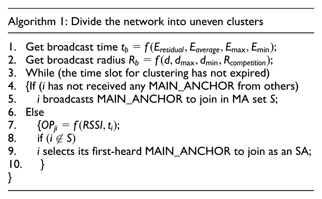
Cluster formation
In a WSN, the time for anchors to broadcast MAIN_ANCHOR is computed according to their residual energy in the first step. The anchors with shorter broadcast time will become the MA automatically. The broadcast time is expressed as follows

where
According to the receiving signal strength indicator (RSSI) from MA j, MA i can establish OP

where
For candidate selection, each anchor broadcasts MAIN_ANCHOR according to the transmission time itself. Hence, the anchor with the highest residual energy first broadcasts its message, while competition radius broadcasting 22 is not the maximum competition one to save energy. For example, the competition radius of anchor j is as follows

where
When ordinary anchors get MAIN_ANCHOR, instead of broadcasting it, they will record the information of the sender. If it is the candidates that get MAIN_ANCHOR, they will not address it. After time
After MA selection, if the ordinary anchor gets only one MAIN_ANCHOR, it will join the cluster. If it gets more than one MAIN_ANCHOR, the ordinary anchor will select the MA with the first-heard broadcast packet (the one with maximum receiving signal strength). Once an ordinary anchor has selected its MA, it forwards message JOIN_CLUSTER to inform this cluster of getting in. When the MA gets the message, it uses a high performance media access control (MAC) protocol, such as time division multiple access (TDMA), to ensure that all the nodes in the cluster send data without collision and sleep without the sending time to save energy.
After a period of working time, if more anchors die from running out of energy, which means a shorter network lifetime, the network sustainability will be poor. The more are the anchors that survive, the longer the life span attained by the network will be. The clustering scheme above can be named LEACH-ED. Compare the network survival time with that of the well-known hierarchical network protocol, that is, LEACH and LEACH-C,23,24 using node survival time and network residue energy as the evaluation index. The simulation parameter is shown in Table 1 in section “Experimental result and discussion.”
Simulation parameters.

UDP: User Datagram Protocol; MAC: media access control.
As seen in Figures 3 and 4, the new clustering scheme improves the network performance to provide longer network service.

Living nodes in network versus simulation time.

Network residual energy versus simulation time.
Next hop routing selection
MA distributes the clock synchronization signal to its SAs. The inter-cluster data transmission quality is determined by the routing. As shown in Figure 2, the relay anchor, such as MA2 and MA6, only forwards the data from the last main anchor MA1 or MA6 despite data fusion.
At the beginning of inter-cluster data transmission, it is not necessary to decide the next hop, which is the same as in traditional routing, and it only broadcasts its packets with

Packets forwarding in TIME-DRIVEN OR.
As mentioned above, there will be more than one candidate relay capable of receiving and forwarding packets such as B and C, which will cause duplicate redundant packets. Traditionally, the original packets specify their relative priority, and packets are forwarded according to the priority. This will not only increase the length of the original packets with a lower effective transfer rate but also require the forwarding anchor locating candidates and their priority in advance. The intelligent response method will eliminate packet redundancy, reduce the interaction of packets, and improve the effective transmission.
Forwarding anchors determine their response time according to the difference values of OP between themselves and sending anchors. They do not need extra information interaction, thanks to intelligent response. Suppose that the OP of the relay anchor R is
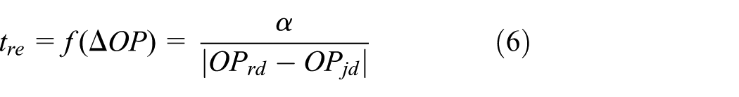
where
In its response time, hearing a higher priority anchor forwarding the packets, the relay will delete the packet copies (see lines 5 and 6 of Algorithm 2 for more details). Without sensing other higher priority forwarding of the packets, the anchor acts as a relay to forward packets. As shown in Figure 5,

Experimental result and discussion
In this section, the performance of the proposed TIME-DRIVEN OR protocol is investigated using both the simulation tools Win.exe+Cygwin+ns2.35 and a hardware test for our self-developed evaluation platform. The simulation of the protocols is for end-to-end delay, network throughput, and packet loss rate. The simulation results are shown in section “End-to-end delay, average network throughput, and packet loss rate.” The positioning error is tested in section “Positioning error on the evaluation platform test.”
End-to-end delay, average network throughput, and packet loss rate
The simulation parameters are shown in Table 1. In this part, TIME-DRIVEN OR is compared with a state-of-the-art OR protocol, that is, ExOR. 6
The simulation uses a shell to write a batch of simulation files to ensure the accuracy of the data. For each sending rate, it simulates 15 times, yielding 15 .tr documents. The file size determines whether the file data is reliable. Small file data result in deletion of the file. Finally, nearly 10 more reliable .tr documents are selected, and they are analyzed by an .awk file already written to obtain the end-to-end delay and the average network throughput. Statistically, the end-to-end delay time of each .tr file is different, but the time fluctuates around a value, and the average end-to-end delay time can be acquired. The statistics of the average end-to-end delay at the same sending rate are recorded as a .dat file. As shown in Figure 6, the TIME-DRIVEN OR can achieve an end-to-end average delay decrease in approximately 0.1 s; although at the lowest point, the optimization is not typically significant.

End-to-end average delay versus packet sending speed.
Figure 6 mainly illustrates a sending packets’ size of 512 bytes and a packets’ sending speed of 28.5 PCS. Due to the average throughput, instead of the total throughput, calculated, a shorter start time yields a higher throughput. As shown in Figure 7, with the increase in time, the average throughput gradually approximates to a stable value. The throughput of ExOR remains approximately 120 kbps, which for TIME-DRIVEN OR is approximately 250 kbps after modification. Comparing the two figures, the modified TIME-DRIVEN OR can significantly improve the network throughput.
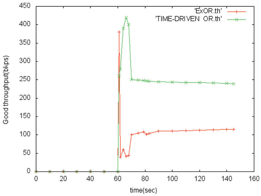
Good throughput versus the sending time.
The source anchor has a constant bit rate. The sending packet is 512 bytes, and the packet loss ratio of ExOR and TIME-DRIVEN OR is compared as shown in Figure 8.

Packet loss ratio versus packet sending speed.
With the increase in the packet sending speed, the packet loss rate of both ExOR and TIME-DRIVEN increases. TIME-DRIVEN OR has lower packet loss ratio than that of ExOR. The response time, which determines the packet routing of TIME-DRIVEN OR, is influenced by the residual energy and the RSSI. However, the forwarder priority of ExOR is put in every packet header. The packet loss ratio is frequently caused by packet congestion; thus, TIME-DRIVEN OR is more robust with respect to packet sending speed.
Positioning error on the evaluation platform test
The research of UWB positioning performance is based on our self-developed evaluation platform, as shown in Figure 9. The platform supports multiple tags in an extensible positioning area. Every positioning subarea has one MA and three SAs. The MA periodically sends time check packets to the SAs, and the SAs maintain the clock synchronization with the MA. The tags send Blink packets to the anchors. After receiving the Blink packets, the anchors send the data back to the server to calculate the precise location coordinate.
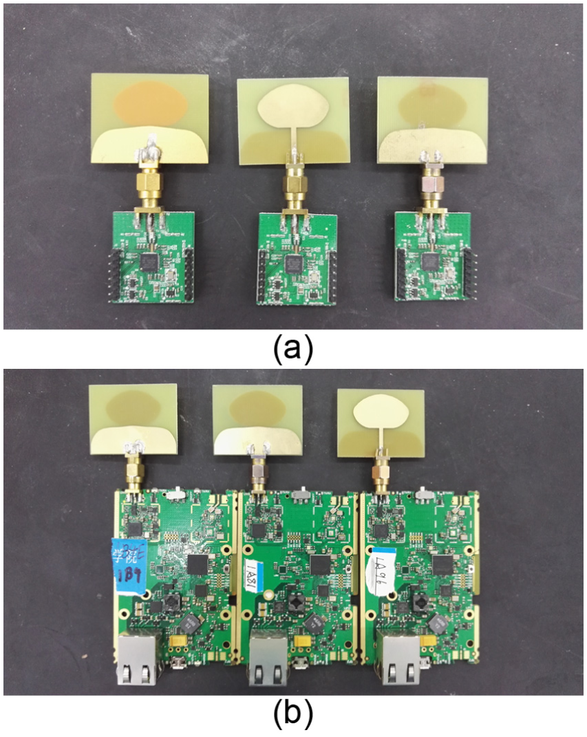
Hardware system: (a) the tags and (b) the anchors.
A total of 30 tags are tested 50 times in each round. The monitored network topology is shown in Figure 2, with the tags evenly distributed in the area. The positioning error is defined as the average Euclidean distance between the real position and the estimated position of N tags. This is expressed as follows

where N is the total number of tags with real position
The test is conducted with various numbers of tags and under the continuous extension of the area. As shown in Figure 10, the localization error of the proposed TIME-DRIVEN OR is lower than those of ExOR and LEACH. For both of them, the localization error becomes larger when the area is extended with more test tags. The clock packets are forwarded to the anchors via different routing with various node survival times, delays, and packet loss rates. The anchors maintain relative clock synchronization to calculate the positions of the tags. Moreover, the control of the temperature drift of crystals and the optimization access schemes can further improve the positioning precision.
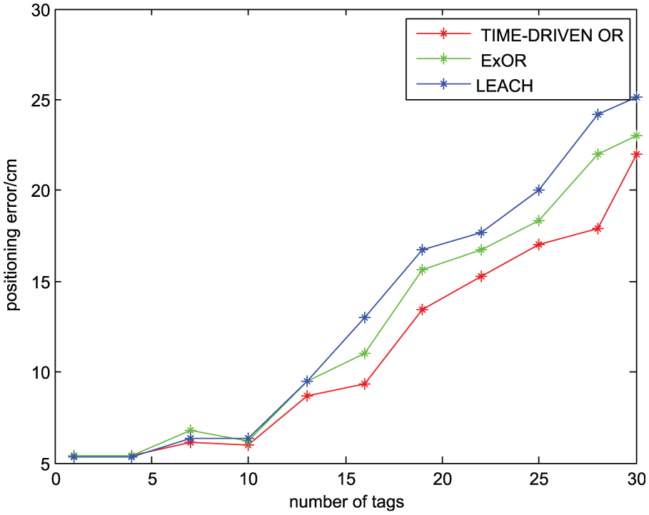
Positioning error versus number of tags.
Conclusion
In this article, we analyze the extensibility of the UWB indoor positioning network. Multiple MAs’ relative clock synchronization is modeled, based on which an energy-balanced clustering scheme is proposed. The anchors with shorter broadcast time become MAs automatically, and the ordinary anchors select their first-heard broadcast anchor as their header. After cluster formation, the relay anchor is intelligently sensed during its response time. Without hearing any other higher priority anchor forwarding packets, it will forward the packets as a relay. Both the cluster formation and the relay anchor selection are time driven without more overhead. Finally, the performance of TIME-DRIVEN OR is simulated and analyzed; moreover, the extension scheme based on our self-developed evaluation platform is tested.
There are two directions for further work: the capacity of the multiple tags model and the mobile tags handover from one positioning cell to another, based on which our hardware platform will be updated simultaneously.
Footnotes
Academic Editor: Gang Wang
Declaration of conflicting interests
The author(s) declared no potential conflicts of interest with respect to the research, authorship, and/or publication of this article.
Funding
The author(s) disclosed receipt of the following financial support for the research, authorship, and/or publication of this article: This study is supported by Major research and development plan of Hainan Province (SQ2016GXJS0098), National Natural Science Foundation of China (61461017), Natural Science Foundation of Qiongzhou University of China (QYQN201432), Sanya Institute of Science and Technology Cooperation Project (2014YD13), and Key Technological Project of Hainan Province of China (ZDXM2014085).