
Abstract
In this article, the ultra-wideband technology for localization and tracking of the robot gripper (behind the obstacles) in industrial environments is presented. We explore the possibilities of ultra-wideband radar sensor network employing the centralized data fusion method that can significantly improve tracking capabilities in a complex environment. In this article, we present ultra-wideband radar sensor network hardware demonstrator that uses a new wireless ultra-wideband sensor with an embedded controller to detect and track online or off-line movement of the robot gripper. This sensor uses M-sequence ultra-wideband radars front-end and low-cost powerful processors on a system on chip with the advanced RISC machines (ARM) architecture as a main signal processing block. The ARM-based single board computer ODROID-XU4 platform used in our ultra-wideband sensor can provide processing power for the preprocessing of received raw radar signals, algorithms for detection and estimation of target’s coordinates, and finally, compression of data sent to the data fusion center. Data streams of compressed target coordinates are sent from each sensor node to the data fusion center in the central node using standard the wireless local area network (WLAN) interface that is the feature of the ODROID-XU4 platform. The article contains experimental results from measurements where sensors and antennas are located behind the wall or opaque material. Experimental testing confirmed capability of real-time performance of developed ultra-wideband radar sensor network hardware and acceptable precision of software. The introduced modular architecture of ultra-wideband radar sensor network can be used for fast development and testing of new real-time localization and tracking applications in industrial environments.
Keywords
Introduction
The fourth industrial revolution, also known as “Industry 4.0,” is a frequently discussed topic nowadays. In the Industry 4.0, most of the work should be carried out by autonomous robots which will require visual feedback to enable their safe orientation in the working area, coping with obstacles, cooperation with humans and correct manipulation of objects, for example, identification and placement of components. Additional sensors will be needed to gain more and the accurate information for the autonomous robots. The main goal of the robot design is its optimization for production and its specifications. To fulfill these requirements, proper selection and identification of the sensors to be used for the detection and tracking of the objects is necessary. In this case, tracking of the robot movements is considered in an industrial noncooperative environment.
Different types of imaging techniques (photogrammetry, stereoscopy, structured lightning, time of arrival (TOA), and laser triangulation) are commonly used in industry and for robot navigation especially, together with others exploited for monitoring and quality control. It is crucial to know which objects are to be measured or localized to choose the right imaging technique. An overview and comparison of machine vision techniques used for robot navigation is provided by Perez et al. 1 These machine vision techniques were compared in terms of accuracy, range, sensor weight, safety, processing delay, and their influence on the environment. Some more industrial vision systems for monitoring and quality control were published in the work of Labudzki and Legutko. 2 Their use for the safety of the employee in industrial environment enhancement together with robot navigation is described by Wöhler. 3 Depending on the tracked target, they can be oriented on scene or on object tracking. For scene monitoring, they are mounted on a mobile robot and exploited for mapping, localization, and detection of obstacles, 4 or terrain classification. 5 In the object-oriented applications, the camera is usually mounted on the end effector of the robot’s manipulator (eye-in-hand configuration), in order to acquire new images by changing the camera position. The time-of-flight method with a camera for robot monitoring in eye-in-hand configuration was published in the work of Alenya et al. 6
We can conclude from the above mentioned that the machine vision techniques in connection with robotics have become main research priorities in industrial scenarios. Also, growing demand for indoor as well as outdoor localization systems is experienced in the last decade. Several methods based on different technologies and devoted for various environments are currently under research. The main are acoustic, 7,8 optical, 9 and radio-frequency (RF) methods. We can divide RF methods as continuous wave (CW), for example, the wireless local area network (WLAN) and the radio-frequecy identification (RFID), 10 and impulse. CW systems have disadvantages like low accuracy, insufficient multipath interference immunity and it is also problem if a large number of sensors are required. Short ultra-wideband (UWB) pulses have proved to be suitable for indoor use. Their short duration ensures multipath effects immunity and offers highest time resolution. Because of UWB very strict energy emission limits, 11,12 they are designed for short-range, that is, indoor sensing. This article deals with such a UWB localization technology system exploited for robot arm localization behind an obstacle.
The penetration depth of RF signals into the dielectric materials typically decreases as the signal frequency increases. However, due to the huge bandwidth of the UWB systems, and their proper distance resolution in correspondence with the achieved material penetration capabilities, an interesting property of the UWB sensors working in high-frequency bands is their ability to detect not only targets located in line-of-sight (LOS) but also objects located behind nonconductive obstacles (non-light-of-sight (NLOS), objects in dust, smoke, thick fog, etc.). 13 Localization of moving robots in 2-D space was discussed in the work of Chang and Sahai 14 and in 3-D space. 15,16 Several basic applications of UWB sensors for indoor and outdoor robot localization in LOS and NLOS scenarios were proposed based on the above-mentioned potential of UWB technology and the current state of the art of the radar signal processing.
There are many theoretical approaches to localization of objects in 2-D and 3-D, for example, TOA, angle of arrival, and measurement of received signal strength. For the radar device, several RF illuminators were proposed. They include conventional UWB radars (impulse radars, noise and pseudo-noise radars, the frequency-modulated continuous wave (FMCW) Doppler radars, stepped-frequency radars, etc.) 17 and nonconventional approaches based on WiFi application (e.g. the work of Chetty et al. 18 and Adib and Katabi 19 ). Experimental results gathered from object localization using these methods show that they are enabled for reliable localization of, for example, humans. Our experiments with the robust M-sequence UWB radar focused on the robot localization proved that even the robot behind an obstacle is visible. In this article, we show that using more sensors connected into the UWB sensor network (UWB-SN) is an efficient approach. UWB-SN improves target detection and localization capabilities by widening the identification angle of the target. The sensor network is able to exploit spatial diversity of the target scattering to decrease complexity of the monitored environment.
Theoretical aspects of exploitation and performance of the UWB-SN for object tracking were described, for example, in the work of Chang and Sahai. 14 In the publication, it was shown that the Cramer-Rao lower bound target position estimation by UWB-SN is inversely proportional to the number of measurements executed by m transmitters and n receivers. The results confirmed that application of UWB-SN increases the probability of correct target detection as well as improvement of localization accuracy. Localization methods based on UWB-SN for humans localization were experimentally validated by Rovnakova and Kocur 20 and Jovanoska and Thoma. 21
State-of-the art overview shows that the basic localization methods and algorithms for the UWB-SN are available. Still, UWB-SN real-time hardware and software has to be developed for practical application of discussed UWB-SN. As far as we know, no UWB-SN for detection, localization, and tracking of generic objects which could be potentially used for the above-mentioned scenarios has been described in available literature sources. Some solutions are in the work of Oppermann et al. 22 (sensor network for outdoor sports and lifestyle applications) and the work of Zwirello et al. 16 (indoor scenarios). Both sensor networks were designed for the localization of the target with active markers. That is the main difference between the UWB-SN described in this article and the UWB-SN discussed by Oppermann et al. 22 and Zwirello et al. 16
Based on a wide range of promising applications of UWB sensors mentioned in this article, considering the advantages of the UWB technologies and robot localization methods as well as the current state of the art in the UWB-SN implementation area, we decided to develop the testing equipment for a wireless real-time UWB-SN. The equipment can be used for the development of various UWB-SN applications for detection, localization, and tracking of moving objects. In this article, we introduce the novel hardware structure of the abovementioned equipment, which will be represented by sensor network with centralized architecture using new wireless M-sequence UWB radar (localization sensor with an embedded processor and standard WLAN interface creating the communication infrastructure for UWB-SN, Figure 8). The main contribution, will be described in the next sections, is the proposed hardware concept of UWB-SN localization device.
The impulse response (IR) method will be used for the localization of moving objects. The IR approach is too complex to be included in a single paper in details; therefore, it will be described very shortly here. The applicability of the proposed UWB-SN concept will be illustrated on offline processing of the data captured from experiments oriented on the moving robot tracking in NLOS scenario. The results show that the introduced concept of UWB-SN is interesting and promising.
UWB systems are here described in terms of application possibilities and exploitation of UWB illuminating signals for measurement, which use systems based on continuously transmitted electromagnetic wave. In the spread-spectrum systems, the occupied frequency band is considerably wide. However, in combination with extremely low power, occupation of the spectrum is not that significant and brings the advantage of improved system robustness in terms of transmission channel parameters.
UWB systems based on continuously transmitted electromagnetic wave
The M-sequence-based systems discussed in this article can be classified as the devices with continuously radiated electromagnetic wave. The stimulation signal is emitted continuously in contrast to the conventional impulse radars which transmit short pulses. As shown in the simplified schematics of the M-sequence generator (Figure 1), the clock signal is modulated by a pseudorandom bit sequence. A linear feedback shift register (LFSR) consisting of sequential logic circuits is used to generate the pseudorandom sequence. 13

Simplified block schematics of the M-sequence generator.
The basic parameter of the signal is the periodicity of the stimulation signal given by the number of shift register bits. The period M is given by

where N is the number of the shift register bits dependent on the system used, usually 9, 12, or even 15 for the most recent systems. Periodicity can be considered as an advantage because it allows use of receiving circuits working at lower frequencies than the clock frequency of the M-sequence (stimulation signal) generator of the transmitter. It means that receiver operates in so-called subsampling mode and uses the stroboscopic effect for the sampling of the received signal. The principles are described in more details in the work of Rovnakova and Kocur 23 and Razavi. 24 The transmitted signal is a noise-like stochastic signal. Its waveform in the time domain after the sampling process is depicted in Figure 2.

Part of the generated pseudorandom binary sequence waveform.
The maximum length binary sequence (MLBS), also known as the M-sequence, is a special type of a pseudorandom binary sequence (PRBS). The term pseudorandom is used, because the stimulation signal x(t) has a certain period (dependent on the LFSR length), after which the bit sequence is repeated. Therefore, it is not the real stochastic, but a quasi- or pseudorandom signal. Parameters of the pseudorandom signal are very close to the real random signals. As an example, the autocorrelation function Rxx(τ) can be mentioned as follows

The autocorrelation function has the short impulse shape (similar to Dirac impulse) and the power spectrum of the pseudorandom signal x(t) is given by the Fourier transformation of its autocorrelation function as follows

The PRBS signal 25 consists of elementary pulses (chips), whose number is dependent on the generator LFSR length and which are pseudorandomly distributed within a single signal period.
Signal whose autocorrelation function is narrow has a large bandwidth. Therefore, it is appropriate to use such a signal as the stimulation signal, that is, signal transmitted by the UWB sensors with high resolution dependent on the clock signal frequency. By examining the cross-correlation function Rxy(τ) between the mentioned transmitted (stimulation) signal and the received signal, we can obtain various information about the space illuminated by the stimulation signal. The cross-correlation function is defined by the following

The information of interest is included in the IR h(τ), especially in its shape, position, magnitude, and other parameters which can be seen directly from the IR (Figure 3), or can be calculated, as for example the effective bandwidth. When observing a target, the IR includes information about the behavior of the target placed between the antennas (e.g. between the transmitting and receiving UWB sensor antenna feeding points) under the influence of the radiated signal. The IR, as well as the auto and cross-correlation functions, is given by the convolution


Possible shape of the received IR. IR: impulse response.
For the equation between the transmitted stimulation signal x(t) and the system response y(t), we can write

Then, if the autocorrelation function is the Dirac impulse δ(τ), equation (5) can be simplified

From the practical point of view, equation (7) means that the cross-correlation function of the received and transmitted stimulation signals is proportional to the IR function. Length of the IR function is proportional to the length of the autocorrelation function of the transmitted signal x(t) and it can be directly considered as the IR of the object illuminated by the stimulation signal x(t) (OUT-object under test).
Regarding the operating frequencies, these devices are capable of operation from tens of Hz up to tens of GHz. Therefore, they easily cover the whole UWB band with a large reserve. Generated stimulation signal waveform in time domain is depicted in Figure 2, where a part of the signal period can be seen as measured in real time. The spectrum of the signal is shown in Figure 4 and the received signal in the form of the IR in Figure 3. Common IR processing algorithms may consider various IR parameters as its rising and falling edge, width, shape, or amplitude.

Generated M-sequence in baseband.
UWB sensor systems
The UWB devices operating with the continuously transmitted electromagnetic wave modulated by the M-sequence are possible to connect with each other and realize cooperative sensor networks and systems. Under the UWB sensor system, we can imagine one or more sensors using ultrawide frequency spectrum in defined band, in our case in baseband up to approximately 6 GHz. Individual sensors (sensor nodes) may be connected by different interfaces into the UWB-SN. These interfaces can be classified according to their use as wireless (RF communication modules operating in unlicensed the industrial, scientific and medical (ISM) bands) and wired interfaces. The wireless interfaces transmit mostly synchronization pulses, because the devices in the UWB-SN require proper synchronization for their correct function. On the other hand, wired interfaces distribute the clock signal to all nodes and synchronization is performed by each node autonomously.
Basic UWB sensor node design
The basic configuration of the UWB sensors used nowadays depicted in Figure 5 is the result of the development of the M-sequence UWB devices.
26,27
The scheme of the UWB sensor can be divided into the following blocks according to their functions: Basic block diagram of a UWB sensor. UWB: ultra-wideband. Transmitter – Input and output amplifiers connected to the clock signal input and M-sequence generator output. – The M-sequence generator responsible for the generation of stimulation signal according to its internal feedback structure. It may include 9 or 12 (the newest version 15) bit LFSR which specifies sensing range. In the case of a 9-bit LFSR, the range covers several meters, if the 15-bit version is used, the sensing range can achieve tens to hundreds of meters (250-300 m). The sensor resolution can be adjusted by the clock frequency, while even the resolution of tenths of a millimeter can be achieved under optimal conditions. Because of their sensing range, the UWB sensors are also known as the short-range devices. – The transmitter also includes synchronization circuits with binary divider. – Modulator used for optional modulation of the output signal. Receiver or a pair of receivers – Similarly to the transmitter, the receiver has amplifiers on its inputs and outputs as well. However, the cascade low noise amplifier (LNA) together with buffers and the other front-end circuits is placed at the input of the receiver. – Wideband sampling gates with a track and hold amplifier responsible for tracking and measurement of instantaneous input signal level, that is, equivalent time sampling. – The actual device concept depends on the given application and working conditions of the sensor. For example, thru-wall measurements and object localization in 2-D space use the conventional block schematic shown in Figure 5. For other scenarios, for example, for a sensor network for 3-D mapping, n-such sensor topologies can be used, or n-receivers, or n-receivers and m-transmitters can be used alternatively.
28

The parts of the transmitter and the receiver are described in more details in the work of Sachs. 13
Modifications of UWB sensor devices
As mentioned above, the UWB sensors as the wideband devices are basically multipurpose and principally modular devices in terms of clock signal time base settings as well as in sense of a number of transmitters and receivers, for example, more transmitters and receivers can be used for multiple input multiple output configuration. These systems can be applied mainly in distributed configurations of the sensors, for example, to improve monitoring of moving targets and its accuracy in complex environments. Thanks to its relatively simple structure and robust timing and synchronization system, it is easy to extend the devices to an arbitrary number of input and output channels and therefore to the arbitrary number of sensor network nodes. The solution is depicted in Figure 6. This type of the modified UWB sensor node has been successfully used as a wideband system for noninvasive scanning in medical applications. 29

Block diagram of a multichannel structure of the UWB sensor. UWB: ultra-wideband.
However, the standard structure of the sensors with a single transmitter extended with low-pass filters for UWB systems 30 and two or more receivers, as shown in Figure 5, is used in most cases. The basic version of the UWB sensor can be extended by circuits for wireless synchronization between the transmitter and receiver. The synchronization over the wireless link (Figure 7) adds a degree of freedom in terms of arbitrary positioning of the UWB sensor transmitter and receiver. The main problems of such systems are contact interruptions and interference from external sources which cause difficulties in narrowband channels. A possible solution for the realization of such a sensor could be the use of narrowband microwave systems combined with a narrow radiation angle of the antennas used for synchronization. Moreover, if the transmitter moves with respect to the receiver, it is necessary to ensure stable visibility conditions. Such a system could be used under laboratory conditions, but it is not that straight-forward in real environments. In this case, the solution for the synchronization of two sensors described in the next section is more viable.

Transmitter and receiver synchronization by wireless link.
Sensor node with RF communication module
The conception of the analog part (transmitter and receivers) of the UWB sensor remains unchanged according to the block diagram in Figure 5. However, the sensor or the sensor node is equipped with an additional RF communication module. We use the term sensor node, because thanks to the wireless access to the nodes, the UWB-SN can be easily created. The sensor network consists of a given number of nodes, which allow for distribution of control commands and mutual synchronization. As opposed to the conception from Figure 7 which transmits the clock signal directly over the wireless interface, in this case, control commands for individual nodes are transmitted (e.g. synchronous start of all sensors at the same time). Under the node, a complete UWB sensor (transmitter and receivers), including the RF communication module, is meant.
Another example could be a system, where along with the synchronization signals, the preprocessed data stream from the individual UWB sensors is carried over the radio channel. In addition to the RF communication module, this type of sensor has to be equipped with a low-power data processing unit based on an advanced embedded controller platform. Dependent on the application, it is possible to apply various mathematical algorithms on the measured data. In the case of the proposed sensor network, the UWB sensor node can be exploited for the movement tracking and detection of the robotic arm in definite space in a noncooperative environment. The UWB sensor node by itself can execute advanced algorithms, for example, background subtraction, detection, and localization in space. 31 –33 At the Department of Electronic Engineering and Multimedia Communication in cooperation with the Ilmenau University of Technology (TUI), the prototype of the proposed sensor node as well as the sensor network was realized. 34 Consequentially, a commercial wireless UWB sensor node was constructed (Figure 8). Data from these wireless UWB sensors can be sent via WLAN to the Data Fusion Centre, which ensures primary sensor initialization, synchronization, and processing of the received data in real time. 35 In our case, an ordinary personal computer was used as the Data Fusion Centre because the conventional WLAN interface was exploited for the RF communication. Therefore, a tablet or another mobile device with a standard WLAN interface can be used as the Data Fusion Centre also.

Node of the UWB sensor network (m: explore sensor head with embedded controller). (a) Photograph and (b) backside of m: explore sensor head with power, data, and controller connectors.
UWB sensor network
When designing the UWB-SN, it is crucial to select proper UWB sensors (radar devices). As mentioned earlier, radar devices using various illuminators were developed. They include “conventional” UWB radars (impulse radar, noise and pseudo-noise radar, FMCW Doppler radar, stepped sine radar, etc.) or new nonconventional approaches exploiting WiFi systems. The scenario of the UWB-SN usage described in this article includes localization and tracking of the moving robot. The developed UWB-SN is applicable to LOS as well as NLOS scenarios. The essential concept of the target localization in the UWB-SN is based on the assumption, that raw radar data are represented by the IRs of the environment, through which the electromagnetic waves propagate from the transmitting T(x) to the receiving R(x) antennas of the sensors. Considering these requirements, the M-sequence UWB radar was chosen as the sensor for the UWB-SN. 13 The reasons for this decision can be shortly summed up as follows:
Experimental testing of the M-sequence UWB sensor and developed signal processing algorithms has proved that by their combination we are able to localize and track the robot arm. Moreover, the UWB sensor has additional useful properties. Its operational parameters, such as system bandwidth (up to several GHz), resolution accuracy (1–3 cm), and range (17–40 m) are controlled by the system clock frequency. Therefore, the single radar system can be easily adapted to various scenarios. The transmit power of a single radar sensor is usually between 1 mW and 10 mW. Thanks to the M-sequence signal exploitation, the transmitted energy is equally distributed along the whole M-sequence period.
The unique characteristic of the M-sequence UWB radars is their ability to operate simultaneously in the same frequency and time period, while their mutual interference is negligible. The detailed analysis of the mentioned property in the work of Zetik 36 showed that this effect is caused by the clock frequency deviation between the individual system clock sources of the radars. It was proved in the work of Zetik 36 that only a few kHz difference between the clock frequencies of the radars ensures negligible correlation between the M-sequences transmitted by them and therefore their mutual interference can be omitted. This property of the M-sequence radar systems was considered as their major advantage during their development. Therefore, no special algorithms are needed to control the UWB-SN in terms of time and frequency coordination of the individual sensors. The ability of the M-sequence UWB systems to operate correctly also under narrowband interference condition and in coexistence with other sources of electromagnetic radiation (WiFi, cellular phones, communication infrastructure of the UWB-SN, radio and TV broadcast, Bluetooth communication, etc.) is considered as their further exquisite advantage over the other systems. 13,37
Architecture of the UWB-SN
The proposed UWB-SN has the star topology with a single central node (CN) and multiple UWB sensor nodes (SNs, Figure 9). In the proposed network, the CN operates in the master mode, while the sensor nodes operate as slaves. Each sensor node consists of the M-sequence radar and the embedded controller, that is, data processing unit equipped with a WLAN transceiver. Signal captured by the UWB radar sensor node can be independently processed by the embedded controller using the algorithms for tracking of the moving targets behind an obstacle for example introduced in the work of Rovnakova and Kocur. 32 The processing consists of multiple steps, including background subtraction, weak signal amplification, detection, TOA estimation, compensation of the obstacle influence, and target localization. Locally estimated coordinates of the targets [x, y, optionally z] form a low-speed data stream, which can be transferred through the WLAN interface to the CN. The CN, a standard personal computer with a WLAN interface, combines the data from the individual sensors. Data combining for the discussed UWB-SN can have centralized architecture 20 and all locally estimated target coordinates gained from SNs can be processed in the Data Fusion Centre. Data transferred to the common center will be time-synchronized and transformed to the common coordinate system. The data sets from each SN form input data for the moving target tracking (MTT) system, or even a multiple MTT system.
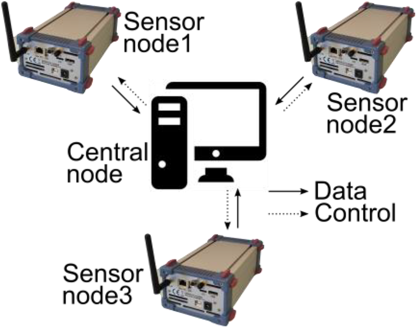
Star topology of the proposed UWB sensor network. UWB radar and signal processing unit are included in each sensor node, data fusion and localization are implemented in central node equipped with the personal computer. UWB: ultra-wideband.
UWB-SN components
The discussed SN uses the UWB radar radiating the pseudorandom MLBS (M-sequence) as the sensor, as described in the second section. As mentioned above, the M-sequence radar has multiple basic advantages which make it an ideal choice for short-range sensing. It transmits continuous low-power signals in mW range even in the thru-wall applications. The power levels are lower than typical GSM devices or WiFi hotspots radiate during transmission. Therefore, the M-sequence radar radiation is safe for humans in the proximity of the device.
During our research, the SN was created, which uses the new M-sequence UWB sensor equipped with the embedded controller and WLAN interface manufactured by Ilmsens GmbH (Ilmenau, Germany) (Figure 8). The UWB radar node monitors the area of the interest and gathers continuous series of IRs (raw radar data) of the environment, through which the electromagnetic waves propagate (from transmitting to receiving antennas of the sensor). The embedded controller with the WLAN interface receives the raw radar data and by executing the algorithms described, for example, in the work of Rovnakova and Kocur, 32 it is able to estimate coordinates of the moving targets. The embedded controller executes all computationally expensive processing in the SN and acts as the signal processing core. Because it is equipped with the WLAN interface, it ensures the real-time communication between the SN and CN as well. A more detailed description of main software functions which can be implemented in these SN can be found in the work of Drutarovsky et al. 34 The hardware functions are described in the following sections.
Wireless communication module with integrated core for processing and generation of synchronization signals
Thanks to its versatility, the standard UWB radar front-end can be implemented into a many sensor network consisting of the control unit (concentrator) and for example three UWB sensors.
The UWB sensor, as a single node of the sensor network, is equipped with three antennas. One antenna enables for transmitting the stimulation signal, while the remaining antenna pair is used for reception of the reflected signals. The technical parameters of the sensor node used in this case are as follows.
RF properties: System clock rate: 13.312 GHz; UWB transmit signal: 12th order M-sequence/ 4095 chips; RF output power Tx: −7 dBm; RF input power Rx1/2: up to 0 dBm, −14 dBm (1 dB compression point); LNAs at the receiver inputs; and T&H buffer in subsampling mode. Digital properties: Digital interface: USB2.0, high-speed (480 MBit/s); ADC characteristics: 2-channel 14 Bit, subsampling ratio 1:512; and Data processing: configurable synchronous averaging (48×–262,144×).
The radar frequency may vary dependent on its application. In this case, the internal clock generator was used. However, it is possible to connect the UWB sensor to an external clock source and use it for various measurement scenarios.
The transmitter core is based on the LFSR which generates the pseudorandom spreading bit sequence. The bit sequence is then mixed with the sine wave signal at the carrier frequency and transmitted as the stimulation signal. The principle is depicted in Figure 5.
The frequency divider is a part of the synchronization unit (Figure 5). The unit ensures synchronous clocking of the sampling circuits of the receiver and capture of exactly one sample from the given period of the received signal (the subsampling principle, as a property of the M-sequence).
In addition, the sensor network nodes are equipped with an additional interface for wireless transmission of the measured data in real time. Therefore, they are capable of, for example, primary data preprocessing by Hadamard transformation and autocorrelation function calculation which outputs so raw IR data. The core of the computational unit consists of a pair of powerful processors on system on chip (SoC) with the advanced RISC machines (ARM) architecture Samsung Exynos5422 (4× Cortex™-A15 2.0 GHz and 4× Cortex™-A7 1.4 GHz), which are a part of the ODROID-XU4 platform manufactured by the Hardkernel co. (Anyang, South Korea). 38 The module also includes a 2-GB RAM memory, the embedded multi-media card (eMMC) flash storage, 3-D graphical accelerator Mali™ T628, various standardized interfaces to interconnect with the UWB sensor, and a radio communication module which operates in a non-licensed band according to the 802.11 standard. The computational power of this module is fully sufficient for the primary data processing and synchronization by pilot signals between the sensor nodes and the control node of the sensor network. Therefore, the individual sensor nodes are responsible for the signal reception, primary data preprocessing, and their transmission to the common network node (data fusion center), where the final data processing occurs. As the result of this process, the trajectory of the robot arm, or even arbitrary moving objects (e.g. operators) is plotted.
Wireless UWB-SN application
In this case, the UWB sensor was designed mainly for localization and tracking of the robot arm (or its predefined part) which was moving in the defined space in the xyz coordinates behind the obstacle. This solution has high application potential, especially in situations, when conventional sensors have high failure probability or if the conventional sensor functionality may degrade because of the noncooperative environment with, for example, low visibility, dust, or even in the case of fire. Another advantage of the proposed solution is that the UWB sensor can be located outside the working area of the robot arm and does not require direct visibility.
For this application scenario, a configuration of UWB sensors exploiting four receiving antennas and one transmitting antenna was used. A pair of receiving antennas was connected to the first sensor module, which radiated the illumination signal from the transmitting antenna and monitored the moving target in horizontal plane as well. The other pair of the receiving antennas was connected to the second sensor module which observed the target’s movements in vertical direction. This way, the sensor network was created of two UWB radars which were strictly synchronized to allow for the further data processing of the received signals. Finally, the data were combined and the resulting movement of the robot arm in the spatial coordinates was displayed. Using the additional sensor connected into the wireless sensor network, it is possible to effectively improve the target detection and localization by widening the target identification observation angle. Such a sensor network is able to exploit the spatial diversity of the target scattering to decrease complexity of the monitored environment.
The UWB sensor antennas were placed relatively close to the target, just behind the reach of the robot gripper. The measurements were taken in an LOS as well as in NLOS scenarios behind the obstacle simulated by the plasterboard wall (Figure 10). Various scenarios of the robot arm movements were observed, from simple horizontal and vertical movements to a complex trajectory in all possible directions. Because of the data processing and display complexity in 3-D space, only the linear horizontal movement is displayed in Figure 10. The arm was moving in a perpendicularly way to all antennas.

(a) Measurement scenario. (b) Through-the-wall experimental sensor network application based on the M-sequence UWB radar system with robot gripper movement detection from the tracking algorithm (blue dashed line). (c) Impulse responses—detail of the area of interest. (d) Number of 553 impulse responses with varying amplitudes as well as rising and falling edges, in the case, when the arm was moving in a perpendicularly way to the antennas. (e) Radargram from RX1. (f) Radargram from RX3.
Measurement was performed in the short time interval, and results from the measurement and the signal processing from receiving antennas Rx1 and Rx3 are shown in Figure 10(e) and (f), respectively. These figures represent raw radar data (top) and after background subtraction (bottom) arranged to the radargram. The tracking algorithm result (blue dashed line) for this scenario is shown in Figure 10(b). For better comparison, the real movement between the two endpoints with known predefined coordinates (red points P1 and P2) is also shown in the figure. Comparing the known robot arm trajectory between the given endpoints and the trajectory estimated by the tracking algorithms, it is possible to consider the accuracy of the described method.
The proposed method requires the proper antenna configuration. 39 The antennas were placed as follows: One pair of the receiving antennas was placed horizontally, while the transmitting antenna was located between them. The second pair of receiving antennas was placed above and below the transmitting antenna (the transmitting antenna was again placed in the middle). For better scenario description, please refer to Figure 10(a) and (b), where the UWB radar, antennas, simulated obstacle, and the robot arm can be seen.
Conclusion
Robots have become a core element of Industry 4.0 and flexibility can be incorporated into them by sensor technologies in order to achieve the requirements and functionalities of the new applications. It is necessary to improve the accuracy and collaborative work with humans, which means making decisions in real time and triggering actions. For these goals, visual feedback is the key issue, thus 3-D machine vision is the future of robotics. In this article, a basic idea of wireless UWB sensing has been explained. All parts of whole UWB system and digital signal processing have been introduced as well. From the experimental results, it can be seen that selected hardware and method of signal processing works quite very well. For the future work will be deployed and tested complex wireless UWB-SN with more UWB sensors for performing of 3-D measurements and advanced data processing.
The article describes wireless UWB-SN hardware for robot gripper monitoring behind the obstacle. It uses star topology with centralized data fusion center. Each SN uses M-sequence wireless UWB radar front-end with 12th order pseudorandom M-sequence and embedded controller as well, developed by the Ilmsens GmbH (Ilmenau, Germany). Preprocessing of radar signals and locally executed signal processing algorithms are performed by the pair of powerful processors on an SoC with ARM architecture Samsung Exynos5422 (4× Cortex™-A15 2.0 GHz and 4× Cortex™-A7 1.4 GHz), which are a part of the ODROID-XU4 platform manufactured by the Hardkernel co. (Anyang, South Korea). Implemented signal processing algorithms are linked as dynamic libraries and can be easily modified in the future development.
It can be seen from Figure 10 that selected method of signal processing works very well for the griper performed simple movements in two axes behind the obstacle, but using more sensors connected into the UWB-SN would be an efficient approach. UWB-SN improves target detection and localization capabilities by widening the identification angle of the target. The sensor network is able to exploit spatial diversity of the target scattering to decrease complexity of the monitored environment and to improve the more accurate sensing even behind the obstacle. Developed UWB-SN has modular architecture that we can easily extend from hardware as well software point of view. Our future development will concentrate on improvement of embedded signal processing algorithms.
Footnotes
Acknowledgement
The authors would like to thank the Slovak Cultural and Educational Grant Agency (KEGA) and the Slovak Research and Development Agency.
Declaration of conflicting interests
The author(s) declared no potential conflicts of interest with respect to the research, authorship, and/or publication of this article.
Funding
The author(s) disclosed receipt of the following financial support for the research, authorship, and/or publication of this article: This work was supported by the Slovak Cultural and Educational Grant Agency (KEGA) under the contract no. 054TUKE-4/2016, the Slovak Research and Development Agency under the contract no. APVV-15-0055, the Slovak Research and Development Agency under the contract no. APVV-15-0692, and the Slovak Cultural and Educational Grant Agency (KEGA) under the contract no. 062TUKE-4/2017.