
Abstract
Underwater wireless sensor network attracted massive attention from researchers. In underwater wireless sensor network, many sensor nodes are distributed at different depths in the sea. Due to its complex nature, updating their location or adding new devices is pretty challenging. Due to the constraints on energy storage of underwater wireless sensor network end devices and the complexity of repairing or recharging the device underwater, this is highly significant to strengthen the energy performance of underwater wireless sensor network. An imbalance in power consumption can cause poor performance and a limited network lifetime. To overcome these issues, we propose a depth controlled with energy-balanced routing protocol, which will be able to adjust the depth of lower energy nodes and be able to swap the lower energy nodes with higher energy nodes to ensure consistent energy utilization. The proposed energy-efficient routing protocol is based on an enhanced genetic algorithm and data fusion technique. In the proposed energy-efficient routing protocol, an existing genetic algorithm is enhanced by adding an encoding strategy, a crossover procedure, and an improved mutation operation that helps determine the nodes. The proposed model also utilized an enhanced back propagation neural network for data fusion operation, which is based on multi-hop system and also operates a highly optimized momentum technique, which helps to choose only optimum energy nodes and avoid duplicate selections that help to improve the overall energy and further reduce the quantity of data transmission. In the proposed energy-efficient routing protocol, an enhanced cluster head node is used to select a strategy that can analyze the remaining energy and directions of each participating node. In the simulation, the proposed model achieves 86.7% packet delivery ratio, 12.6% energy consumption, and 10.5% packet drop ratio over existing depth-based routing and energy-efficient depth-based routing methods for underwater wireless sensor network.
Keywords
Introduction
Underwater wireless sensor networks (UWSNs) are growing in popularity in academics and industries due to their wide range of application domains, including ecosystem monitoring, disaster risk reduction, secondary navigation, energy exploration, and monitoring. Due to powerful unique technologies in underwater monitoring, ocean surveillance, marine surveillance, and custom development for sensing underwater benchmarks, the domain UWSNs has received considerable attention recently. Collecting sensor nodes, base stations, and sink nodes creates a UWSN. 1 In UWSN, all the sensor nodes are strewn across the water, mainly from the exterior to the base. It primarily captures the data and transmits it to the sink nodes, further transmitting it to the base station. Sensors monitor the shallow water ecosystem, including temperature, and transfer the data obtained to a sink node via a single or multiple hops. 2 Numerous directorial protocols have been released in earlier works that consider underwater information sharing via acoustic signals and their shortcomings, including a high failure rate, propagation delay, limited bandwidth, and high energy consumption. 3
In UWSN transmission, three routing methods are typically used. At the first direct transmission method, every sensor node directly sends a datagram to the sink. This may consequence in the reduction of nodes located a considerable distance from the sink endpoint. Its second transmission method is based on a hop-by-hop transmission.
Each entity detects information and transfers it to the sink by choosing the closest neighbor as a routing path. 4
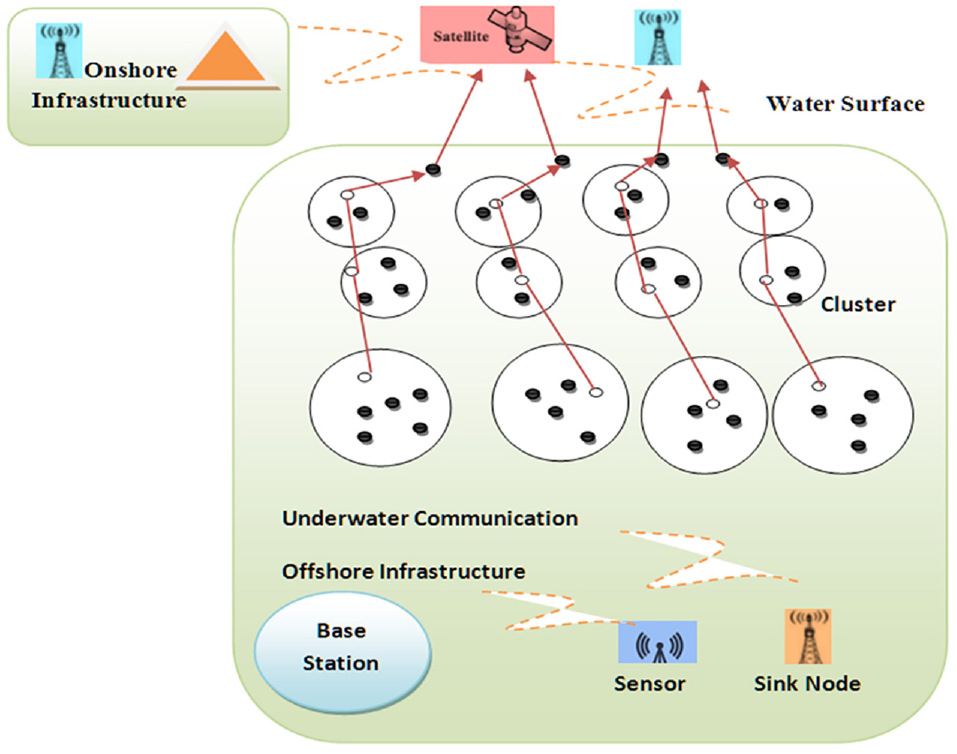
Subsequently, the endpoints’ quantity increases nearer to the sink nodes. Due to this simple fact, nodes stop growing sooner at the beginning stages. Thus further, the performance and lifetime of a network tend to decrease. The third routing protocol, widely recognized as “clustering-based routing,” is one of the most intriguing to investigators. Every underwater detecting node can send its collected data to its correlating cluster heads (CHs). They then send their accumulated data to the Base station. Accurate and complete transmission between nodes is reduced, bandwidth usage is decreased, and the network’s performance is enhanced in this way. 5 Figure 1 shows the architecture of the proposed UWSN. The workings of UWSN are very much similar to traditional WSNs. UWSNs have several distinctive features, that is, long end-to-end delay, limited bandwidth, and high bit error rate. 6

The architecture of UWSN.
A routing technique, which is based on depth data, reduces delay time and energy usage. In this technique, when an information sender sends the data to another node with a lower depth value than the sender and has overlapping lower depth neighbors, the data will be transmitted to the minor depth node. Another popular method is genetic algorithm (GA). 7 It also hunts for optimum solutions by imitating the perfectly natural evolutionary change, can address the optimization issues, and are efficient in determining the best multi-hop path between source and destination. A random framework is commonly used to initialize the GA population. A fitness function analyzes the best participants and picks them for further production. The population can improve, and the best solution is discovered repeatedly, performing selection, mutation, and crossover procedures. 8 However, there are several issues that we must overcome to achieve the performance of UWSNs. The most common issues include battery performance, installation, energy consumption, and long delay. Due to the dynamic environment, UWSN encounters several issues, that is, higher energy consumption, re-transmission, high power consumption, and lack of accuracy. UWSN’s current energy routing study primarily focuses on efficient energy utilization. This research presents a depth-controlled and energy-balanced routing protocol (EEP) based on enhanced GAs for UWSNs. 9
The key contribution of this research includes the following:
The proposed EEP approach for extending the network’s lifetime via depth configuration. To achieve the right balance of energy utilization among clusters near sink nodes and nodes away from sink nodes, EEP rejects the lower energy points and floats up the higher energy clusters.
We have taken forward an approach to determine the time once the nodes must be modified. Then, we establish a process to ensure data transmission, thus increasing the network’s lifetime.
The proposed EEP approach utilized an enhanced genetic algorithm (EGA) to explore optimum multi-hop routing paths for cluster head nodes (CHNs) to transfer network packets toward the Source Nodes and focuses on a modified encoding approach that encrypts routing paths with chromosomes and nodes with genes.
Furthermore, a back propagation neural network (BPNN) applied for data fusion operation is enhanced by incorporating a highly optimized momentum technique that can improve energy efficiency by reducing data duplication and transmission.
This research integrates two clustering routing protocols, GA, and data fusion strategies, utilizing a Depth-Controlled and Energy-Efficient Protocol unique in UWSNs. The simulation results confirmed its efficacy in advancing the lifetime of the network.
This research article is organized as follows: first section covers the introduction, second section covers related works, third section covers materials and methods, fourth section covers results and discussions, and fifth section covers the conclusion and future research.
Related work
Underwater networking utilizes water as the mode of interaction compared to a conventional sensor network; as a result, communications systems for earth-based sensor networks are useless deep underwater. 10 Acoustics transmissions are generally employed for long-distance underwater sensor networks. In contrast, transmitters are utilized for short-distance sea-level information exchange. However, radio signals travel long distances at extremely low frequencies, necessitating massive antennas and considerable network throughput, reducing UWSNs’ entire network lifespan. Furthermore, auditory transmission has a much longer delay than radio transmission; many existing terrestrial wireless sensor methodologies and policies and procedures cannot be comfortably applied to UWSN. 11 Over the last 15 years, UWSNs have been the area of investigation for researchers. Several researchers have suggested several routing algorithms for UWSNs for energy optimization. A few of them are as follows.
Review based on clustering protocols
Various researches have been done based on clustering protocols. The author addressed a low-energy adaptive clustering hierarchy (LEACH) for energy discussed at the research. 1 The CHNs are chosen to use a probabilistic model in the Leach algorithm; however, the residual energy of endpoints is not considered. Gola and Gupta 12 introduced an underwater cluster-based approach depending on electromagnetism for UWSNs. The Voronoi graph establishes clusters, and the Jellyfish breathing procedure is used for CHN classification. This arrangement can obtain high energy saving s well as improve the network.
Simaiya et al. 13 suggested an underwater cluster depending on an adaptive routing mechanism, which significantly improves the network model and creates the route discovery given the exploratory nature of beam routing. The Cluster based Anycast Routing Protocol (CBAR) also uses a route optimization notification process and a power control method. Khan et al. 14 introduced an information fusion method premised on BPNNs. However, they also placed the input sequence of BPNNs throughout directly binding. They set the hidden and output layer upon layer in Basic format. For energy efficiency measures, the fusion data indicating the input information is forwarded to the node. Nazareth and Chandavarkar 15 presented an information gathering and fusion method involving portable SN collection centers. The data elements are chosen regularly. The containers are where data processing occurs, minimizing energy and extending the network’s life. 16
Review based on localization routing
In the study by Goyal et al., 8 a routing method termed “Vector-based Forwarding” is suggested. Almost every sensor is assumed to be aware of its position in this method. Sensors mostly send network packets with the sender, location, destination, and range details. Requires a collaborative effort can only be picked from clusters in a liquid with a specific diameter. In the study by Choudhary and Goyal 17 predicated on the Vector-Based Forwarding Protocol (VBF) guidelines, enhanced methods have been suggested. The proposed scheme increases delivery ratios and reduces energy usage in some instances.
A focused bream routing (FBR) is introduced in investigation 18 to reduce the power consumption in UWSNs. FBR utilizes various transmitting power requirements when choosing a route. The FBR procedure’s RTS/CTS method causes a long end-to-end latency and extreme power consumption. Albukhary and Bouabdallah 19 suggested a depth-controlled route (DCR) discovery. Once the greedy geospatial packet forwarding method fails in route discovery, the entire connected device can modify its detail to organize the network’s topology. DCR is the first geospatial routing technique for UWSNs, which considers the sensor network node opportunity to walk vertically for network optimization.
Based on localization-free routing
A localization-based routing algorithm requires complete location details. However, location tracking is difficult to come by in the underwater ecosystem. As a result, numerous localization-free routing strategies have been designed.
The research used a conventional localization-free routing method named depth-based routing (DBR) which has been used in the previous research. 20 Each endpoint in this procedure is assumed to have a depth sensor. DBR chooses the next forwarder predicated on depth data. DBR is an easy-to-use networking technique. However, it does have some serious flaws, such as high power consumption and long delay. An energy-efficient depth-based routing algorithm (EEDBR) for UWSNs has been developed in the previous analysis 21 to enhance DBR’s power consumption issue. In aspects of energy usage, network lifetime, end-to-end delay, and waiting time, the proposed EEDBR increases efficiency. In the research by Wahid et al., 22 H2-DAB is presented. Here, each entity needs to get a Hop ID. A Hop ID of an endpoint shows the number of hops between the neighbor nodes. The base station chooses the nodes only with the shortest Hop ID as carriers. This results in the void geographic area phenomenon.
Review based on GA
Maqsood et al. 23 presented a hybrid GA to maximize the routing protocol, which encrypts the pathways as genetic material and introduces unique mutation and crossover procedures for recognizing the best possible topology. Furthermore, the fitness function has been created by considering the network’s energy usage, long delay, and bandwidth utilization. Khater et al. 24 developed an efficient GA to maximize the data transmission route discovery by utilizing a straightforward encoding procedure, a unique crossover procedure, and an optimized mutation procedure. They also defined objective functions depending on the energy expenses and flow delay, which can reduce power consumption and expand the network’s average life span. Haque et al. 25 introduced a routing scheme premised on GAs used to find the appropriate paths between source and destination to fulfill the demands of multi-cast conversations, enhancing the delay-tolerant.
Comparison of various routing protocols of UWSNs
Table 1 represents the comparisons of various routing protocols widely used in UWSNs.
Comparison of various routing protocols of UWSNs.

UWSN: underwater wireless sensor network.
Materials and methods
This section covers the proposed EEP method for energy-efficient routing in the UWSNs. 35 The most critical problems with cluster formation are the development of clustering algorithms, the massive decrease in energy consumption for information broadcast, and the optimization of cluster node selection in UWSNs. The proposed UWSN EEP model’s complete working method is as follows.
Proposed energy-efficient routing model
The energy consumption issue is the core of UWSN’s findings. Overcoming the energy consumption of UWSNs is always essential due to the limited energy storage of UWS nodes and the complexity of changing or charging the current battery underwater. To overcome energy issues, we present in this research a depth-controlled and energy-balanced routing protocol EEP for UWSN. This proposed approach adjusts the depths of lower energy endpoints and exchanges them with higher energy nodes to ensure consistent energy utilization in the UWSN.
The proposed Depth-controlled and energy-efficient routing protocol (DCEER) routing protocol also utilized an EGA and DA for UWSNs. The proposed method also used a GA based on a particular encoding strategy, a crossover procedure, and an improved mutation procedure. Furthermore, a BPNN applied for data fusion operation is enhanced by incorporating a highly optimized momentum technique that can improve energy efficiency by reducing data duplication and transmission. Furthermore, the proposed EEP also utilized an enhanced cluster head node (OCHN), choosing a strategy to analyze the remaining energy and directions of each participating nodes. 36 The proposed model used the following assumptions:
There will be two types of participating nodes: First is a UWS node, which is immovable and split further into CHNs and CMNs since clustering, as well as a Sink Node, which is positioned on the outer edge of the surveillance region.
There will be only one Sink Node in the network, the target node that contains the energy supply. Underwater sensor endpoints have restricted energy and do not include energy supply.
Normal undersea nodes all have the same baseline energy and an identification number. A localization method will be used to determine the positions of each of the nodes.
The proposed EEP method utilizes a balance routing protocol (BRP) and Aggregation ring protocol (ARP). The primary goals of these two protocols are to reduce the energy consumption in UWSNs. BRP is a protocol that contains two methodologies and is predicated on hybrid packet forwarding. To evaluate the transmission pathway of the data packets, a location-based routing algorithm establishes a tree with nodes representing sensors and guided edges representing links among sensing devices. The packets will then be sent out using a data-balanced transfer technique. BRP splits each network node’s limited energy. 37 Mostly during multi-hop propagation, a transmitter is reasonably close to the sink node; hence, more energy is required to communicate the overall traffic. Figure 2 shows the design of the proposed model for UWSN. The proposed technique is divided into two phases.
Designing of the proposed UWSN model.
Data transmission phase. The connections established during the first phase are transformed based on the energy level during the second phase. The division method divides individuals consequently to improve desired communication energy balancing acts and dramatically increases the network’s lifetime. 38
Designing of proposed EEP Model for UWSN. The energy consumption scheme of UWSNs distinguishes it from the energy-consuming approach of WSNs due to the attributes of the underwater communication network. The numerical solution is depicted in equation (1)

where a particular node in the network receives an energy threshold value, distance represents the distance between sender and receiver node E (distance, fc) and defines the lowest power consumption by a node to transmit the data fa. Here, i represents the frequency of a node. It can be defined as equations (2) and (3)


Since the exposure region of any sensing element is boundary-based, provided the private network radial distance NR, a node density ND, the width of each circle sector RingW, the max limit of hops MaxH, and the cumulative number of participants Np can be represented as equation (4)
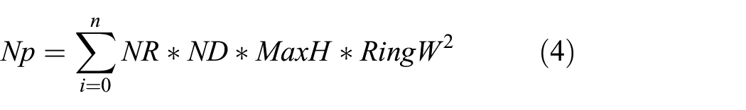
The connectivity of UWSN is subdivided into different small ring areas Ar1 … Arn, from inside to exterior. The maximum number of ring areas can be identified as (RingW/OT) offered RingW, being the network radius, and OT, the optimal connectivity path length threshold of sensing devices. Figure 2 shows the structure of the UWSN model for communication in water.
EGA. This section describes the proposed EGA process used to find the best multi-hop pathways among CHNs and further SNs. It includes a new encoding method and specific selection, crossover, and mutation phases. The best paths can increase data transmission, lower packet drop ratios, and lower energy consumption, extending the network’s lifetime and boosting performance.
Problem formulation. When developing the GA to discover the best pathways, we consider that there are only (N − 1) CHNs and One Sink Node. A Sink Node must be the final destination. A source node is the CHN which requires transferring information. A transmission node is connected to each CHN node in the network. Let Yij, Dij, Eij, and Kij represent the connection indication, connection cost of energy, connection latency, and duration, correspondingly, connecting node i and node j. The time it takes for node i to transfer data packets is Dti, and the time it takes for node j to accept data packets is Dtj.
Dlmax represents the maximal delay of the route. Whenever a connection exists among nodes i and j, the frequency of Yij equals 5. Else the combined value of Yij is 0. We consider the searching for multi-hop routes to be a multi-objective optimization issue, only with the goal of finding the best route at the lowest cost. 39 An objective formula (Fobj) is obtained as follows


Encoding phase in EGA. The EGA method encrypts routing pathways as chromosomes and all the participating nodes as genes. The first gene represents an origin node on a chromosome. The last gene also represents the target node on the set of chromosomes. Because the genes inside each chromosome are not always constant, distinct route optimization pathways have various connections and nodes. Furthermore, a gene cannot repeat at several positions within identical chromosomes. This indicates that every node inside a path from the source to the destination can only be present once to avoid looping and increase the path’s efficiency. Figure 3 illustrates the entire encryption procedure for EGA.

Encryption process in EGA.
Operations in EGA. The proposed EGA method utilizes the following fundamental functions: Initialization Phase in EGA—A pair of chromosomes is used to determine the overall population at the beginning. A GA is wiser to seek an optimum solution since it has additional starting chromosomes. However, the method needs longer to converge and misuses time and energy. A minimal set of chromosomes can consume system resources but also result in adverse consequences. A random selection method is used to begin the chromosomal creation process. The first gene in this research demonstrates the origin node. The origin node’s adjacent nodes provide the second-level gene. In contrast, the next node’s adjacent nodes give the third-level gene, which takes place until the destination node.
The routing scheme in EEP
The whole portion provides the enhanced GA, which is utilized to search for the best possible multi-hop pathways among the sender and receiver nodes. The novel lossless encoding strategy and the septic mutation, selection, and crossover operators are discussed. 40
The best pathways can increase transmission rate, shorter packet drop ratios, and reduce power consumption, advancing network lifetime and enhancing performance. The following steps will take place in the implementation of the EGA method. Figure 4 shows the working of the proposed UWSN EEP model.
Step 1: The base station keeps track of UWSN’s sensor devices and creates cluster neighborhoods.
Step 2: Using the proposed EEP strategy, each cluster territory obtains information from cluster members. This method accepts each independent node’s energy condition when transmitting data. At the same time, a large portion of the portable sensor clusters is placed into standby mode. As a result, the early stages of project network nodes placed into the sleep state can be quickly spotted. The preliminary energy can be assigned to be supervised. 41
Step 3: The cluster endpoints are chosen from every team of cluster territories. The Neighbor Discovery Methodology is used to establish head-to-head connectivity. This method assigns the corresponding Cluster transmitter and assists sustainable energy in information exchange in the simplest way possible.
Step 4: This should also be retained at every cycle of cluster node creation. Once new digital endpoints arrive or are relocated, this method predicts the accepted nodes and the cluster territories.
Step 5: Sensor nodes are switched from one position to combine information over the network utilizing GA after composting each cluster group and newly appointed Cluster nodes in each cluster territory.
Step 6: Protocol extracting the energy level at each cluster community and rebalancing the cluster endpoints is universally recognized as the most straightforward way. After that, they anticipate the base station condition beyond passing to the dead battery scenario to drop through the Energy Scheduling strategy in the system.
Step 7: In the UWSN, access points can use the Localization Method to monitor their position to reduce energy consumption and expand the network’s lifetime.

Proposed UWSN EEP model workflow.
Simulation results and discussion
This section covers the simulation details of the proposed UWSN EEP model, existing DBR, and existing LEACH protocol. The network lifetime, power consumption, and packet drop are the critical parameters used to evaluate a routing protocol’s efficiency and performance in communication. The investigations were performed using the MATLAB simulator. 42 MATLAB can take advantage of sensor nodes, analysis techniques, pattern recognition, computer vision, object recognition, regulatory compliance, control mechanisms, communication systems, remote sensing, and other applications. It is created by MathWorks and is also a shortened form of “matrix and laboratory.” Matplotlib is a comprehensive solution for science investigation, structural engineering, and a wide range of scientific problems requiring accurate numerical estimations. Figure 5 shows the MATLAB script for keeping the clusters alive in UWSN. Table 2 shows the details of the simulation parameters.

MATLAB code of proposed EEP UWSN.
Details of simulation parameters.

Energy consumption
The overall energy utilized by the network for transmissions, receiving, and data gathering is referred to as energy consumption. 43 Figure 6 shows the simulation outcomes for energy consumption of the UWSN network for various routing protocols. The proposed EEP models have better energy consumption levels over existing DBR and EEDBR protocols. The simulation was performed from 10 to 100 rounds. Once the number of rounds increases, energy consumption also increases. In the network at round 20, the proposed EEP methods show 12.5% of energy consumption, minimum. As for round 80, the proposed EEP model shows 20% energy consumption which is better than existing DBR and EEDBR methods.

Graph total energy consumption (in %) versus the number of rounds.
Packet delivery ratio
A packet delivery ratio (PDR) is calculated as the overall packets transmitted to the total packets received from a source and destination to a target device on the network.44,45 Figure 7 shows the packet delivery ratio % of the UWSN network for various routing protocols. The proposed EEP method offers a better packet delivery ratio % than the existing DBR and EEDBR for all the possible instances in the network. The simulation results show that for node 50, the DBR method shows 83.5% PDR, EEDBR shows 85.47%, and the proposed EEP method shows more than 90% PDR. As the number of nodes is 100 to 300, the proposed EEP method offers more than 7% PDR than EEDBR and more than 10% PDR over the DBR method.
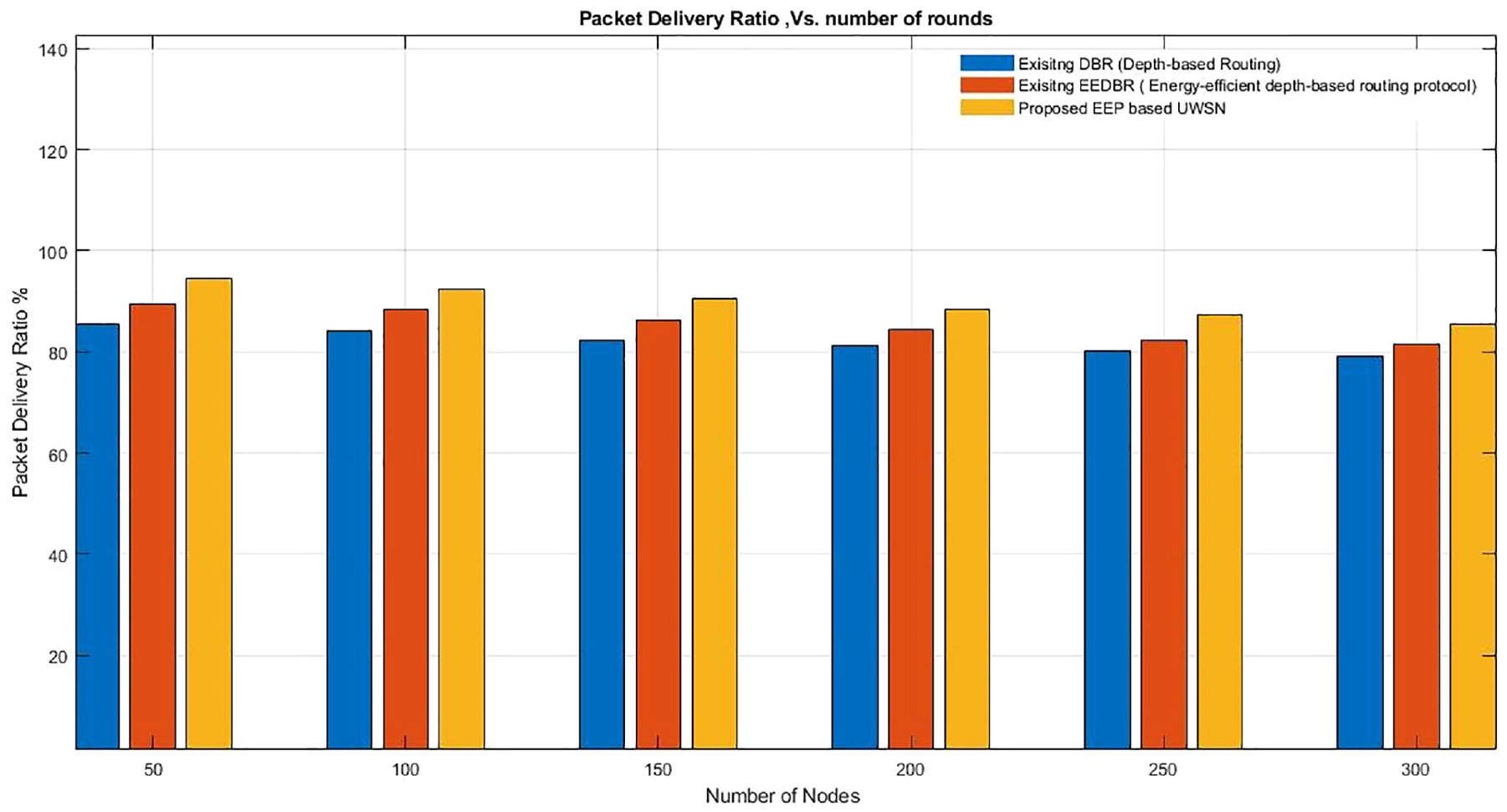
Graphpacket delivery ratio (%) versus number of rounds.
Packet drop ratio
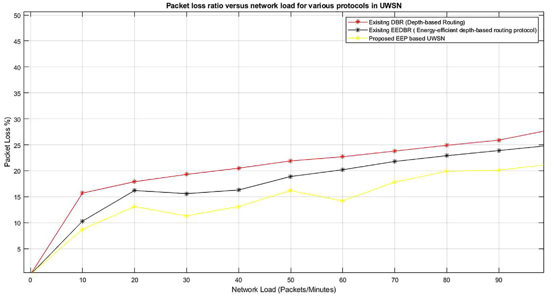
Packet loss can occur whenever one or even more sent packets fail to reach their desired target. 46 Suppose a node in the network joins the UWSN, it will not participate in the transmission process until it receives authorization. Figure 8 shows the simulation results for the graph packet loss ratio of the UWSN network for various routing protocols. This graph is plotted among Packet loss % and Network load (Packet/Minutes). The proposed method performs better for all instances from 10 to 90 packets per minute from network load. The proposed EEP method has a Less than 10% packet loss ratio for network load 10, which is minimum in the network. DBR shows 15.5% of other existing methods in this instance, and EEDBR shows 10.5% packet loss. The proposed EEP method has a better packet loss ratio for network loads of 10 to 90 packets per minute.

Graph packet loss ratio (%) versus network load (packet/minutes).
The lifetime of the network
A performance measurement parameter in UWSNs is network lifetime, measured as the time it takes for the first sensor’s power to run out. 47 The frequency of active nodes, connections, and distribution impacts the network’s average lifespan. A performance measurement parameter in UWSNs is network lifetime, measured as the time for the first sensor’s power to run out. The frequency of active nodes, connections, and distribution impacts the network’s average lifespan. Figure 7 shows the simulation results for network lifetime and the number of nodes when the radius is 5 km. Figure 8 shows the simulation results for network lifetime and the number of nodes when the radius is 10 km. Figures 9 and 10 indicate that the network’s lifetime of all techniques gets reduced with the rise in the network radial distance and number of nodes. The proposed EEP method shows a better network lifetime in both scenarios when the radii are 5 and 10 km and number of nodes is 50 to 300.
Graph network lifetime versus number of nodes (for radius 5 km).

Graph network lifetime versus number of nodes (for radius 10 km).
Figure 11 shows the simulation graph for network lifetime and various network radius. This graph shows that once the network radius increases from 1000 to 8000 m, the network’s life is also reduced. The proposed EEP method offers a better network lifetime over existing DBR and EEDBR methods in all the instances of the UWSN network.
Figure 12 shows the simulation results for network lifetime regarding the number of nodes alive. The graph is plotted among the number of active nodes versus a number of rounds. The curve shows that the active nodes decrease once the number of rounds increases from 100 to 1000.
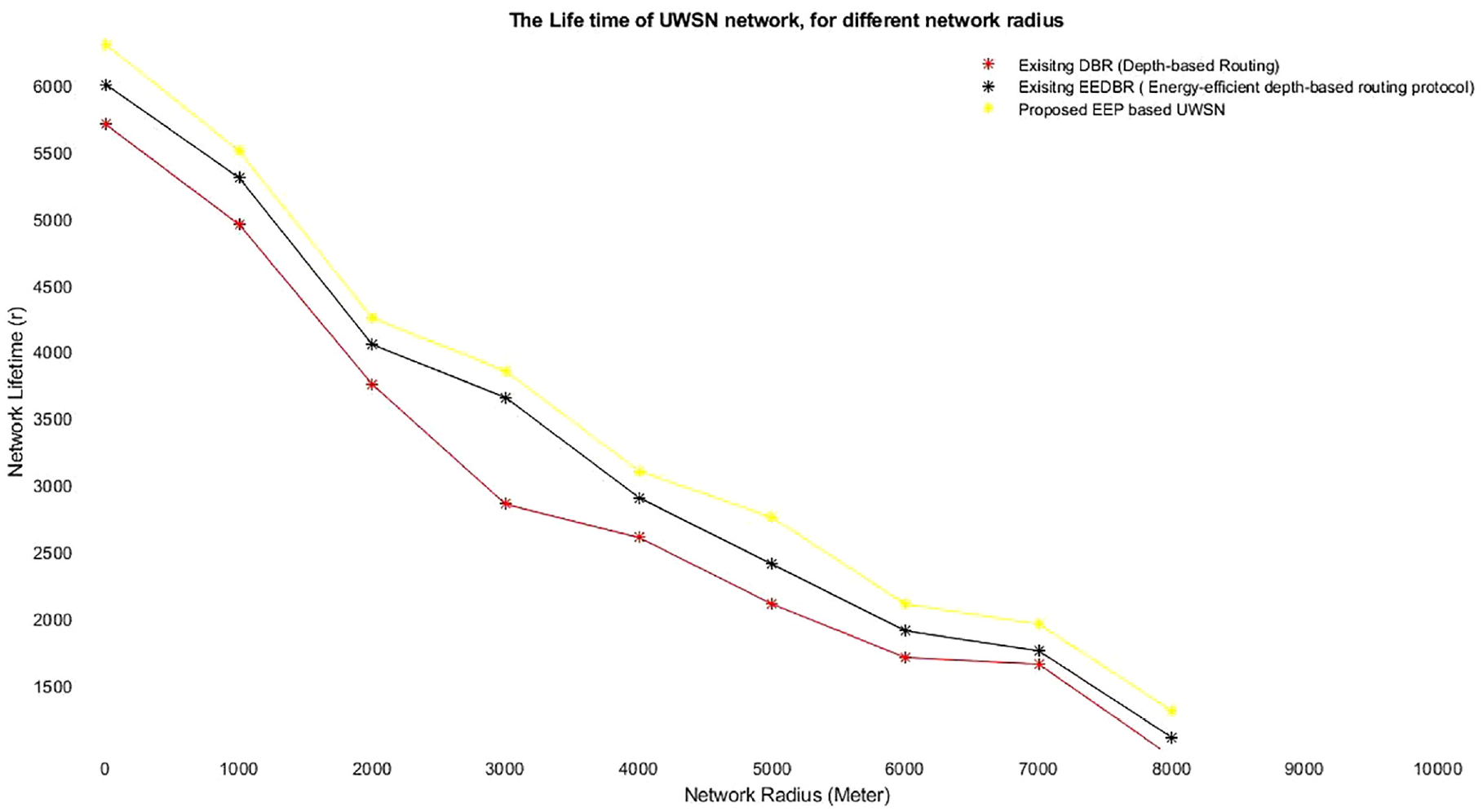
Graph network lifetime versus different network radius (in Meter).

Graph number of nodes alive versus number of rounds.
The proposed EEP method shows a higher number of alive nodes over existing DBR and EEDBR methods.
Throughput
The total components of relevant data that a platform can transform in a predetermined period are throughput. 48 The throughput is calculated for two scenarios with a 5 and 10 km radius. The network throughput results for scenario 1 (where the radius is 5 km) are displayed in Figure 13, and scenario 2 (where the radius is 10 km) are depicted in Figure 14. The simulation results clearly show that the network throughput is higher when the number of nodes is lesser in both scenarios. The proposed EEP method shows better throughput results over existing DBR and EEDBR methods.

Graph network throughput versus number of nodes (for the radius of 5 km).

Graph network throughput versus number of nodes (for the radius of 10 km).
Network transmission loss results
The power at one stage in a UWSN transmission network is compared to the power at another location and the connection.16,49–52 The lesser results for network transmission loss show better performance. Figure 15 shows the simulation results of network transmission loss for various methods in UWSN. This graph shows that the network transmission loss increases once the network’s radius increases. The proposed EEP method shows better performance (less transmission loss) for all the network instances from a radius of 1000 to 8000 m over existing DBR and EDBR methods.

Graph network transmission loss result versus network radius.
Conclusion and future work
In UWSN, the replacement of batteries is complex due to the wide size and typical structure of water, so energy-efficient routing in UWSN is always required. This research presented an energy-efficient protocol (EEP) based on EGAs, including a depth threshold and energy level division for UWSNs. The technique is divided into two phases: routing and data transmission. The proposed EEP model is developed to fix high energy usage, less packet delivery ratio, throughput, long end-to-end delays, and network transmission loss. The underwater surveillance region is layered across this proposed EEP protocol, and IoT device sensors are categorized for each layer. The proposed EEP method and existing DBR and EEDBR methods are implemented in the MATLAB simulation environment for UWSN. The simulation outcomes demonstrate the strength of the proposed EEP method in terms of better performance, that is, higher throughput, less packet loss percentage, higher packet delivery ratio, better network lifetime, and alive nodes. The spatial advancement of the energy ring sectors and the larger model of dynamic depth thresholds will be considered in future work. We will also try to reduce the time complexity of the proposed EEP model, which is currently higher (O(n2)), over existing DBR and EEDBR methods.
Footnotes
Handling Editor: Lyudmila Mihaylova
Declaration of conflicting interests
The author(s) declared no potential conflicts of interest with respect to the research, authorship, and/or publication of this article.
Funding
The author(s) disclosed receipt of the following financial support for the research, authorship, and/or publication of this article: The Research General Direction has funded this research at Universidad Santiago de Cali under call no. 01-2021.