
Abstract
Dose measurement with ionization chamber is essential to deliver accurate dose to the tumor in radiotherapy. The cylindrical Farmer-type ionization chamber is recommended by various dosimetry protocols for dose measurement of radiotherapy beams. The air-equivalent graphite wall Farmer-type ionization chamber (FAR 65 GB) of active volume 0.65 cm3 with aluminum as the central electrode material was fabricated. Various dosimetric parameters were studied for the newly developed ionization chamber in cobalt-60, 6 and 18 MV photon beams. The preirradiation and postirradiation leakage of the chamber was within 0.08%. The long-term stability and the stem effect of the chamber were within 0.07% and 0.3%, respectively. The sensitivity of the ionization chamber was found to be 22.15 nC/Gy. The chamber shows linear response with dose for cobalt-60, 6 and 18 MV photon beams. The ion recombination correction factor increases with increase in bias voltage. For all energies and field sizes, the polarity correction factor is almost closer to unity. The ion recombination and polarity correction measurements show that the polarizing potential and polarity recommended during the calibration of ionization chamber should be used for routine measurement to avoid the uncertainty. The chamber response is independent of dose rate and energy. The chamber is cost-effective and shows precise and reproducible response. The study carried out confirms that the newly fabricated ion chamber can be used in the measurement of absolute dose for high-energy photon beams.
Introduction
The aim of radiotherapy is to deliver dose to the tumor with an accuracy of −5% to +7% of the prescribed dose. 1 In order to deliver accurate dose, the dose verification with ionization chamber in water or water-equivalent phantom is essential, as this quantity relates close to the biological effects of radiation. The cylindrical thimble-type ionization chamber is recommended for calibration of radiotherapy beams. The dose delivered to a given point in the medium is determined by measuring the amount of charge produced in the small air cavity placed in the medium. 2 –4 The dose delivered to the medium can be calculated from the total charge or saturation charge produced in the air cavity according to Spencer-Attix theory. 5
The design and specification of the thimble chamber used for dose measurements in radiotherapy are described in various protocols. 1,6 –8 According to the protocols mentioned in the literature, the cavity volume of the chamber should be between 0.1 and 1 cm3. The internal diameter of the chamber air cavity should be less than 7 mm, and length should be less than 25 mm. The construction of the chamber should be homogeneous, but the central electrode material differs from that of the wall material due to technical reasons. The choice of the material plays an important role in the energy response of the chamber. Graphite wall ionization chambers usually have better long-term stability and uniform response than plastic wall chambers. However, plastic wall chambers are more robust and suitable for routine measurements. The change in ambient temperature and air pressure should be taken into consideration for the ionization produced in the air cavity. The humid air may also affect the chamber response. As ionization chamber is an instrument of high precision, attention needs to be paid to test their dosimetric performance.
The use of ionization chamber in teletherapy beam requires various correction factors. The response of ionization chamber depends on radiation dose, dose rate, chamber material, volume, chamber polarity, applied voltage and beam quality. Although the clinical radiotherapy departments require more than 1 Farmer-type ionization chamber, it is not possible to have as the commercially available chambers are very expensive. The present study focuses on the design and dosimetric characteristics of newly developed Farmer-type cylindrical ionization chamber (FAR 65 GB) by Rosalina Instruments India Private Limited (Mumbai, India).
Materials and Methods
Chamber Design and Characteristics
The thimble-type cylindrical ionization chamber is designed according to the specification provided by the International Atomic Energy Agency Technical Report Series (IAEA-TRS) protocol. 1,6 Table 1 shows the detailed technical specification of the chamber. The newly developed chamber is shown in Figure 1.
Farmer Chamber (FAR 65 GB) Technical Specification.


Farmer-type ionization chamber (FAR 65 GB).
Treatment Units
Theratron 780C telecobalt machine and Clinac DHX linear accelerator (Varian Medical Systems, Palo Alto, California) were used for dosimetric measurements. Clinac DHX is a dual-energy linear accelerator capable of delivering 6 and 18 MV photons and 5 electron beam energies. It incorporates single-focused millennium MLC as tertiary collimator that consists of 60 pairs of tungsten leaves with central 40 leaf pairs of 5-mm projected leaf width at isocenter and 10 leaf pairs of 10-mm projected leaf width on either side of the isocenter.
Dosimetric Study
The chamber characteristics and various dosimetric parameters were evaluated for the newly developed Farmer-type ionization chamber. The Farmer chamber was used along with the calibrated Dose1 electrometer (Scanditronix Wellhofer, Germany) for all dosimetric measurements, and the calibration factor for the electrometer is 1.
Preleakage and postleakage check
The ionization chamber was connected to the electrometer with power-on condition and kept for an hour to attain the thermal stability of the chamber and electrical stability of the electrometer. The natural (preirradiation) leakage may occur due to dirty connectors, wet desiccators, no sufficient time given for the instrument to stabilize, and no preirradiation dose given to the chamber. The preirradiation leakage of the chamber was tested for a period of 5 minutes, and measurements were repeated for 5 times. Radiation-induced (postirradiation) leakage associated with the chamber is identifiable only after the exposure of the chamber to radiation. If radiation-induced leakage is present, there will be a continued collection of charge even after the beam has been turned off at a similar rate. Radiation-induced leaks vary in their magnitude; nevertheless, it may be ignored if the leakage is small. The radiation-induced leakage of the chamber was tested for a period of 5 minutes, and measurements were repeated for 5 times. A radiograph of the developed farmer chamber was obtained to check the chamber specification and manufacturing defect.
Stability check
Stability check of ionization chambers is vital as they are relatively fragile and may be with little or no visible sign of damage. Strontium-90 (90Sr) check source was used to verify the overall sensitivity, long-term stability of the ionization chamber and its measuring assembly. The source, chamber and measuring assembly had been kept in the measuring room, at least 1 hour prior to the measurement, to ensure that the source and chamber are at similar temperature. The stopwatch, barometer and thermometer were used in the measurement. The ionization chamber was inserted into the source holder in a reproducible position closer to the source. The time required to give a specified charge was determined using stopwatch. The measurement was repeated 10 times. The atmospheric pressure and temperature in check source housing were recorded, before and after measurement. The instrument was corrected for air density with the atmospheric pressure (P) in mbar and temperature (T) in °C using the following relation:

The standard pressure and temperature values are 1013.2 mbar and 20°C. The standard uncertainty and standard error of the mean for short- and long-term stability were obtained from the corrected reading.
Km and Katt factor
K m is a correction factor that accounts for non-air equivalence of chamber wall of graphite material (ρ = 1.82 g/cm3) and buildup cap material of Delrin (ρ = 1.4 g/cm3), which can be calculated using the following relation 6 :

where α is the fraction of ionization inside the air cavity due to electrons from the chamber wall, (1 − α) is the fraction of ionization due to electrons generated in the buildup cap, s air,wall is the stopping power ratio of air to wall material, (μen/ρ)wall,air is the ratio of mass energy absorption coefficient for wall material to air, s air,cap is the stopping power ratio of air to buildup cap material, and (μen/ρ)cap,air is the ratio of mass energy absorption coefficient of cap material to air.
K att is a factor that accounts for attenuation in the walls of ionization chamber. The value of K att was computed by Monte Carlo method for different types of chambers that are provided in the literature. 6 For cylindrical and thimble-type ionization chambers, the recommended value is 0.990 ± 0.005.
Overall perturbation factor (PQ)
The overall perturbation factor (P Q) is the product of various perturbation correction factors for cylindrical ionization chamber of quality Q, and it can be calculated using following relation 9 :

The factor P cav corrects the response of an ionization chamber for the effects related to the air cavity, predominantly the in-scattering of electrons produce different electron fluence in the presence and absence of air cavity in the medium. P dis accounts for the effect of replacing a volume of water with the detector cavity of the inner radius r cyl (mm), when the chamber reference point is taken to be at the center of the chamber.

P wall (Equation 5) accounts for the difference in photon mass energy absorption coefficient and electron stopping powers of chamber wall material and medium. A sleeve made of silica (ρ =2.3 g/cm3) was used as a waterproof to protect the chamber. 1

where s wall,air is the stopping power ratio of wall material to air, (µen/ρ)w,wall is the ratio of mass energy absorption coefficient of water to wall material, s sleeve,air is the stopping power ratio of sleeve material to air, (μen/ρ)w,sleeve is the ratio of mass energy absorption coefficient of water to sleeve material, and s w,air is the stopping power ratio of water to air for the beam quality Q.
The value of α and τ can be determined for the chamber of wall thickness t w and sleeve thickness t s using Equations 6 and 7:


P cel corrects for the response of an ionization chamber for the effect of central electrode during in-phantom measurements in high-energy photon.
Determination of KQ,Q0
The beam quality correction factor (

The value of
Absorbed dose to water calibration factor
As per the reference conditions recommended for telecobalt beam in the TRS 398 protocol, the chamber was placed at 5-cm depth in water phantom with 10 × 10 cm2 field size and 80 cm source to skin distance (SSD). The measurement was carried out in 34 × 40 × 35 cm3, WP 1D manual water phantom (Scanditronix Wellhofer). The meter reading M developed was recorded for the developed ionization chamber used in this study. The ionization chamber of volume 0.65 cm3 (FC65-G; Scanditronix Wellhofer) having the valid absorbed dose to water calibration factor for reference beam quality (Q0) was used as a reference chamber. With the same measurement condition, the developed chamber was replaced by the reference chamber, and the meter reading M ref was recorded. The calibration factor for the developed ionization chamber was determined from the following equation:

where
Linearity and stem effect
The linear response of the developed chamber was investigated as a function of dose ranging from 0.4 to 4.1 Gy using telecobalt beam. The chamber was placed at 5 cm water-equivalent depth in white polystyrene (ρ = 1.045 g/cm3) phantom with 10 × 10 cm2 field size and 80 cm SSD. The dimension of white polystyrene (RW3 solid phantom material) is 30 × 30 cm2 with various thicknesses of 1, 2, 5, and 10 mm plates. In linear accelerator, the chamber was placed at 10 cm water-equivalent depth in polystyrene phantom with 10 × 10 cm2 field size and 100 cm SSD for 6 and 18 MV photon beams to find the dose linearity as a function of monitor units ranging from 10 to 1000 MU.
For the verification of stem effect, the chamber was exposed at the depth of 5 cm for the field size setting of 10 × 30 cm2 (width × length) and 30 × 10 cm2 (width × length). The percentage variation in response of the chamber for the above-mentioned field size setting reflects the stem effect.
Chamber response with bias voltage
The chamber response was studied by varying the bias voltages from 50 to 500 V, with an increment of 50 V for all 3 beam energies used in the study. The set field size used was 10 × 10 cm2 at 5-cm depth for cobalt beam and at 10-cm depth for both 6 and 18 MV beams.
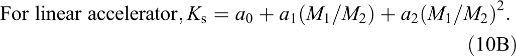
Ion recombination correction factor (ks)
The ion recombination and multiplication are influenced by the potential applied to the ionization chamber. 10,11,12 K s was measured for γ rays of telecobalt and high-energy X-rays of linear accelerator at 5 and 10 cm water-equivalent depth in polystyrene phantom respectively, with the bias voltages of +300 and +150 V for field sizes ranging from 5 × 5 cm2 to 30 × 30 cm2 in 60Co beam and from 3 × 3 cm2 to 30 × 30 cm2 in 6 and 18 MV photon beams. Also, K s was determined for various bias voltages ranging from +50 to +500 V, with +300 V as a nominal operating voltage with 10 × 10 cm2 field size. The ion recombination factor can be experimentally determined using “half-voltage technique” with the nominal operating voltage (V 1) and lower voltage (V 2) for the obtained meter readings M 1 and M 2, respectively, using the following equations:

Polarity correction factor (Kpol)
The polarity effect of ionization chamber was checked for the use of opposing polarizing potential. The polarity effect can be accounted using a correction factor as given in Equation 11.

where M + and M − are the electrometer readings obtained at positive and negative potential, respectively, and M is the electrometer reading obtained with the polarity used routinely (positive or negative).
K pol was measured for 60Co at 5 cm and for 6 and 18 MV photon beams at 10 cm water-equivalent depths in polystyrene phantom with the bias voltages of +300 and −300 V. The measurement was carried out for field sizes ranging from 5 × 5 cm2 to 30 × 30 cm2 in 60Co beam and from 3 × 3 cm2 to 30 × 30 cm2 in 6 and 18 MV photon beams.
Dose rate effect
The measurement was carried out in 6 and 18 MV photon beams at 10 cm water-equivalent depth in polystyrene phantom with 10 × 10 cm2 field size. The chamber response was recorded for 100 MU exposure with dose rate ranging from 100 to 600 MU/min.
Energy dependency
To investigate the energy dependency of ion chamber, measurements were carried out at 5 and 10 cm water-equivalent depth in polystyrene phantom for an exposure of 2 Gy dose in 60Co and high energy X-rays (6 and 18 MV beams) for the field size of 10 × 10 cm2.
Results and Discussion
Preleakage and Postleakage Check
The preirradiation leakage and postirradiation leakage for the developed chamber were 0.48 × 10⁻¹⁰ C and 0.53 × 10⁻¹⁰ C respectively. The measurement shows that the preirradiation and postirradiation leakage of the developed ionization chamber was within 0.08%.
Stability Check
The stability of the chamber was verified using 90Sr check source. The results of the short- and long-term stability of the chamber were consistent with the international standard International Electrotechnical Commission (IEC)-60731 protocol. 13 Table 2 shows the standard uncertainty and standard error of the mean of the dosimeter during stability check. In Figure 2, the radiographic image of the ionization chamber clearly demonstrates that there is no defect in the ionization chamber.
Stability of the Developed Ionization Chamber.


Radiograph of the chamber (FAR 65 GB).
Perturbation Factors
The non-air equivalence of wall material (K m), correction for attenuation by wall material (K att), and displacement correction factor (P dis) were calculated for the chamber, and the values were found to be 0.995, 0.990, and 0.9988 respectively. The values of different perturbation factors calculated for 60Co, 6 and 18 MV photon beams are tabulated in Table 3.
Perturbation Factors for the Chamber (FAR 65 GB).

a K pol and K s for 10 × 10 cm2 field size.
Absorbed Dose to Water Calibration Factor
The absorbed dose to water calibration factor for the chamber was found out by cross-calibration method with the calibrated reference chamber at the reference beam quality (Q0 = 60Co beam). The cross-calibration was done according to the IAEA-TRS 398 protocol, and the value of absorbed dose to water calibration factor (N D,W, 60Co) and the sensitivity of the chamber were found to be 4.514 × 10⁷ Gy/C and 22.15 nC/Gy respectively.
Linearity and Stem Effect
The dose response of the chamber was linear between the dose range from 0.4 and 4.1 Gy with telecobalt beam, and the linear response is shown in Figure 3A. A good linear response was observed for photon beams of 6 and 18 MV ranging from 10 to 1000 MU. The response of the chamber normalized to 200 MU is graphically represented in Figure 3B.

A and B, Linearity of the chamber.
The stem effect of the ionization chamber for the field configuration of 10 × 30 cm2 (width × length) and 30 × 10 cm2 (width × length) was measured and calculated. The percentage variation in response of the chamber for the above-mentioned field size setting was found to be within 0.3%.
Chamber Response With Bias Voltage
The chamber response was studied by varying the bias voltages from 50 to 500 V with an increment of 50 V for all energies as shown in Figure 4. The response was found to be increasing for all energies by 8% to 9% as the applied voltage was increased from 50 to 500 V. It was observed that as the applied voltage is beyond 300 V, the change in ionization response was within 2% for all energies.

Chamber response for the applied bias voltage.
Ion Recombination Correction Factor
The ion recombination correction factor (K s) for different field sizes with 60Co, 6 and 18 MV photon beams for the nominal and reduced voltages is represented in Figure 5A. The variation in ion recombination correction factor was 0.6% in 60Co beam, when the field size was increased from 5 × 5 cm2 to 30 × 30 cm2. Similarly, the variation was found to be 2.6% and 2.7% for 6 and 18 MV photon beams respectively. The recombination correction factor has attained saturation beyond 10 × 10 cm2 field for all beam energies. Figure 5B shows the variation in ion recombination correction factor for different applied bias voltages with 10 × 10 cm2 field size. The ion recombination correction factor was found to increase with increase in bias voltage. The charges produced in the chamber during irradiation are collected completely when the sufficient voltage is applied to the chamber. When the chamber is used below the saturation voltage, some of the charges produced by radiation are recombined, which leads to a loss in dosimetric signal.
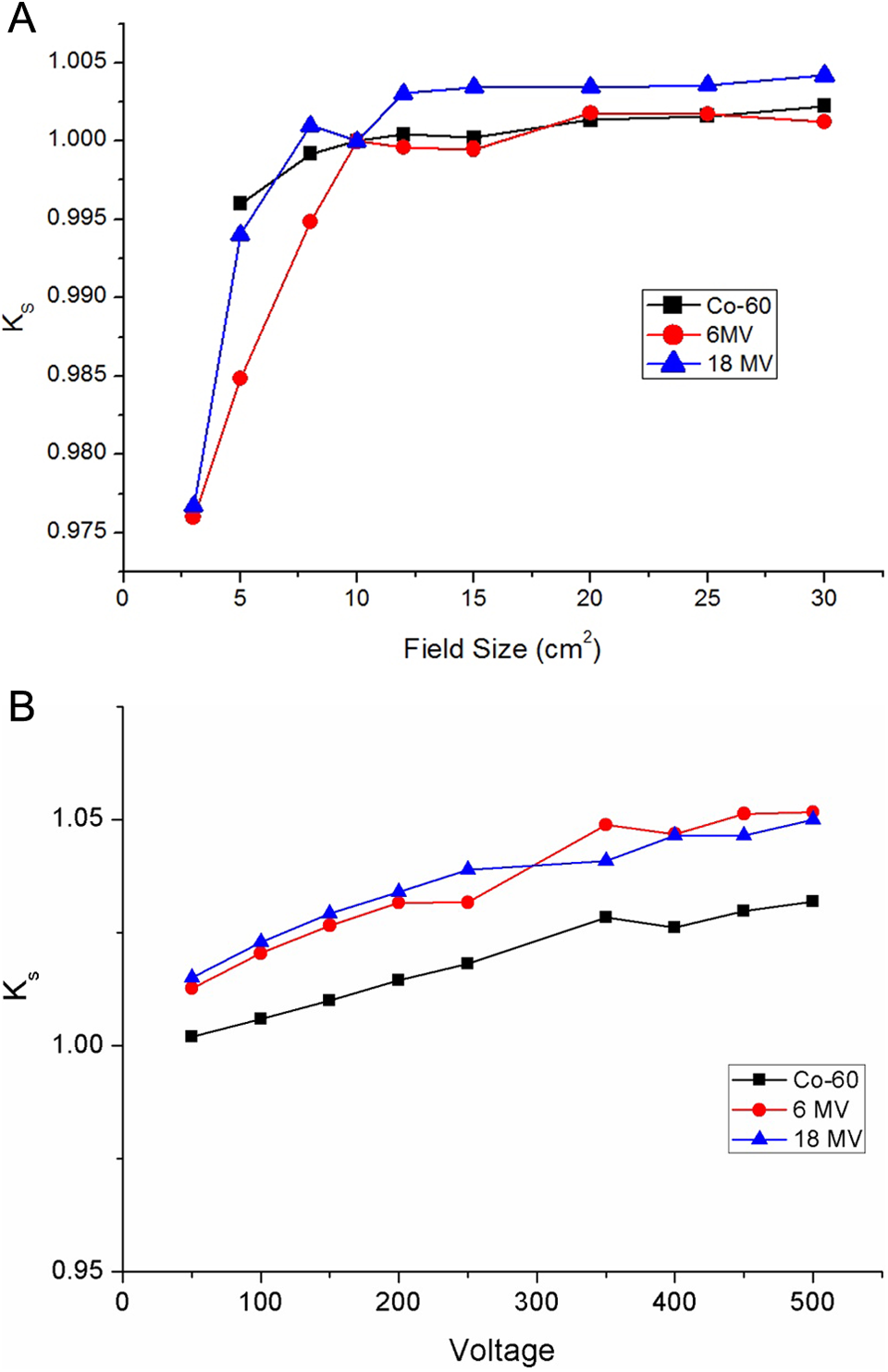
A and B, Ion recombination correction factor.
Polarity Correction Factor
Figure 6 shows the polarity correction factor (K pol) for different field sizes of 60Co, 6 and 18 MV photon beams. No noticeable variation in polarity correction factor was observed for change in field size. The results depicted in Figure 6 show that the difference in K pol noticed was less than 1%. For all energies, the polarity correction factor with varying field sizes was found closer to unity.

Polarity correction factor.
Dose Rate Effect
The ion chamber response for various dose rates ranging from 100 to 600 MU/min for 6 and 18 MV photon beams normalized at 400 MU/min is shown in Figure 7. The maximum deviation was found to be 0.4%. The results obtained show that the response of the chamber is independent of dose rate for both energies.

Dose-rate effect of the chamber.
Energy Dependency
The response of the chamber for energy dependency was determined with different energies of photon beams. Figure 8 shows the plot of energy versus response of the ionization chamber. The dependency of detector on energy does not change significantly (<1%) and was well within the measurement uncertainty. The chamber response was found to be independent of energy.

Chamber response for the energy.
Conclusion
The air-equivalent graphite wall chamber (FAR 65 GB) of volume 0.65 cm3 was fabricated and calibrated against the reference chamber calibrated at the secondary standard laboratory. It is certain that the developed chamber is suitable for dosimetry of photon beams in radiotherapy according to the IAEA-TRS 398 protocol. Added advantages are the cost-effectiveness and long-term stability with leakage less than 0.1%. The measurements carried out with the newly developed ion chamber had shown a linear response with dose, independent of dose rate and energy. The overall uncertainty of the chamber is lesser than the literature recommended values. 14 The valuable work carried with the newly fabricated ion chamber (FAR 65 GB) confirms that this can be used for measuring absolute dose in high-energy photon beams.
Footnotes
Acknowledgments
The authors would like to acknowledge Rosalina Instruments India Private Limited for providing newly developed Farmer-type ionization chamber to carry out this study.
Declaration of Conflicting Interests
The author(s) declared no potential conflicts of interest with respect to the research, authorship, and/or publication of this article.
Funding
The author(s) received no financial support for the research, authorship, and/or publication of this article.