
Abstract
Open surgery requiring cytoreduction still remains the primary treatment course for many cancers. The extent of resection is vital for the outcome of surgery, greatly affecting patients’ follow-up treatment including need for revision surgery in the case of positive margins, choice of chemotherapy, and overall survival. Existing imaging modalities such as computed tomography, magnetic resonance imaging, and positron emission tomography are useful in the diagnostic stage and long-term monitoring but do not provide the level of temporal or spatial resolution needed for intraoperative surgical guidance. Surgeons must instead rely on visual evaluation and palpation in order to distinguish tumors from surrounding tissues. Fluorescence imaging provides high-resolution, real-time mapping with the use of a contrast agent and can greatly enhance intraoperative imaging. Here we demonstrate an intraoperative, real-time fluorescence imaging system for direct highlighting of target tissues for surgical guidance, optical projection of acquired luminescence (OPAL). Image alignment, accuracy, and resolution was determined in vitro prior to demonstration of feasibility for operating room use in large animal models of sentinel lymph node biopsy. Fluorescence identification of regional lymph nodes after intradermal injection of indocyanine green was performed in pigs with surgical guidance from the OPAL system. Acquired fluorescence images were processed and rapidly reprojected to highlight indocyanine green within the true surgical field. OPAL produced enhanced visualization for resection of lymph nodes at each anatomical location. Results show the optical projection of acquired luminescence system can successfully use fluorescence image capture and projection to provide aligned image data that is invisible to the human eye in the operating room setting.
Introduction
Despite the improvements in minimally invasive surgery techniques and endoscopic imaging choices, open surgery is still the choice of surgeons for many procedures where tactile feel, large working space, and other factors are important. Diagnostic imaging modalities including computed tomography (CT), magnetic resonance imaging (MRI), and positron emission tomography/single photon emission computed tomography enable noninvasive detection of primary and metastatic tumors throughout the body for staging of disease and presurgical planning. While minimally invasive surgical approaches are increasingly shown beneficial, open surgery is still the mainstay in many oncologic surgeries. Surgeons rely on tactile as well as visual cues to differentiate cancer from surrounding healthy tissues, particularly as tissue locations shift with patient position, after each incision and during exploration. Therefore, enhancement of tissue contrast by optical reporters that selectively accumulate in cancer tissue, lymphatics or even nerves can greatly improve surgeon confidence, speed procedures, and increase accuracy of resection, eliminating repeat surgeries and increasing cure rates. 1,2
In the operating room (OR), sterility is imperative and space and time are limited. These considerations explain some difficulties in introducing new imaging technologies to the OR. Most intraoperative imaging systems are mobile (CT, MRI, and ultrasound) but are very bulky. These must be wheeled into place alongside the operating table and surgeon for use, then returned when finished. For CT and MRI, intraoperative systems are necessarily bulky and heavy due to limitations of detection technologies. Intraoperative ultrasound requires patient contact and constant guidance by an experienced surgeon. Thus, there is little motivation to elevate ultrasound from standard wheeled units. In contrast, optical imaging provides noncontact and full-field view during imaging. 3 Optical imaging is able to detect biological events ranging from molecular and subcellular levels to organ systems with large field of view (FOV) and high frame rate, resolution, and sensitivity.
Fluorescence Image-Guided Surgery
Optical imaging utilizes nonionizing radiation. At the near-infrared region (NIR; 700-1000 nm), tissue absorption and autofluorescence are minimal, increasing depth penetration and reducing background signal, respectively. 4 Fluorescence imaging enables real-time, high-resolution mapping of contrast agent distribution in superficial structures.
Fluorescence imaging can be utilized to improve visualization in sentinel lymph node (SLN) biopsies. 5 In patients, cancer cells may appear first in the sentinel nodes before spreading to other areas of the body. While peritumoral injection of radioactive colloid or blue dye are currently used in SLN biopsies, fluorescence imaging can be more sensitive and selective, improving the chance of accurate removal. Fluorescence molecular imaging has been demonstrated to improve identification and subsequent removal of ovarian cancer peritoneal metastases in humans. 6
Here we describe a fluorescence image capture and projection strategy, optical projection of acquired luminescence (OPAL) that promises to significantly enhance the ease of use, and adoption of fluorescence guidance for open surgery procedures including real-time guidance of SLN biopsy. This new method features rapid acquisition of fluorescence intensity maps from the operating field and then projects this acquired fluorescence image information directly onto the patient rather than on an out-of-field digital display (Figure 1). The OPAL system will improve workflow in the OR over other methods by providing fluorescence visualization on demand, via nondisruptive, overhead projection, leaving the surgeon free to operate unimpeded.

Artistic rendition depicting the fluorescence-guided surgery enhancement with optical projection of acquired luminescence (OPAL) direct projection. Direct display of fluorescence image information onto the imaging field simplifies use of fluorescence during oncologic procedures.
Materials and Methods
Optical Projection of Acquired Luminescence System
We upgraded our preclinical prototype OPAL system 7 for use in a clinical OR environment. A 2500 lumen, consumer grade digital light processing (DLP) projector provided sufficient brightness and FOV at 1 to 1.5m above the surface. A 0.3 megapixel, monochrome CMOS camera (Firefly MV, Pointgrey Research, Richmond, Canada) with 785 nm EdgeBasic long-pass edge filter (Semrock BLP01-785R-25) was affixed to the projector with FOV centered at 1 m. Excitation light was provided by handheld, high power 780 nm, 420 mW output light-emitting diode (LED; Thorlabs M780L2) with 26.5 mm diameter Carclo polycarbonate collimating lens and 769/41 nm BrightLine single-band bandpass filter (Semrock FF01-769/41-25). The OPAL system was affixed to a mobile LED surgical light (Harmony LED585, Steris Corp, Mentor, Ohio) via custom-machined aluminum adapter fitting the central hub (Figure 2).
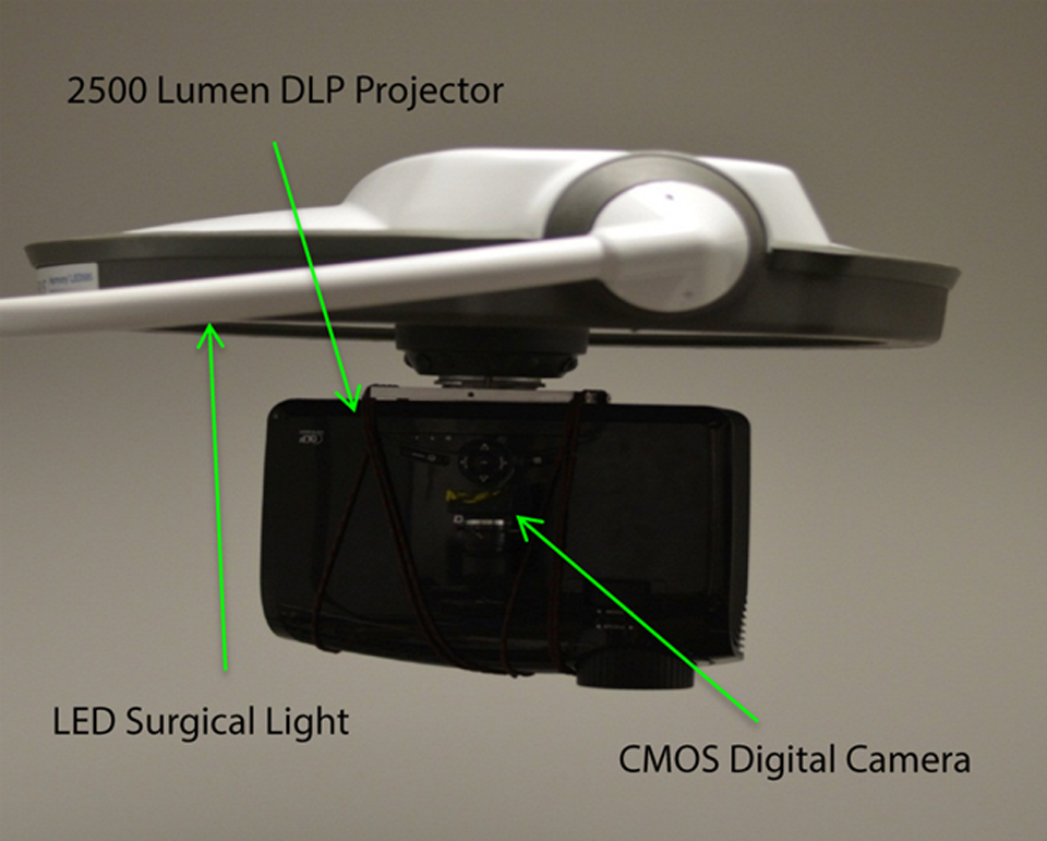
Picture of optical projection of acquired luminescence (OPAL) system attached to light-emitting diode (LED) surgical light for operating room (OR) applications.
System Overview and Design
The complete system consists of 3 essential components: a camera, a projector, and a processing unit. By applying a horizontal integration approach in our design process, we streamlined the system around a single control center or enterprise service bus (ESB). 8 The ESB manages all communication between independent components and subsystems and routes inputs and outputs to their appropriate destinations (Figure 3). For this system, a MATLAB function comprises the ESB, enabling easy modification and multiplatform compatibility.
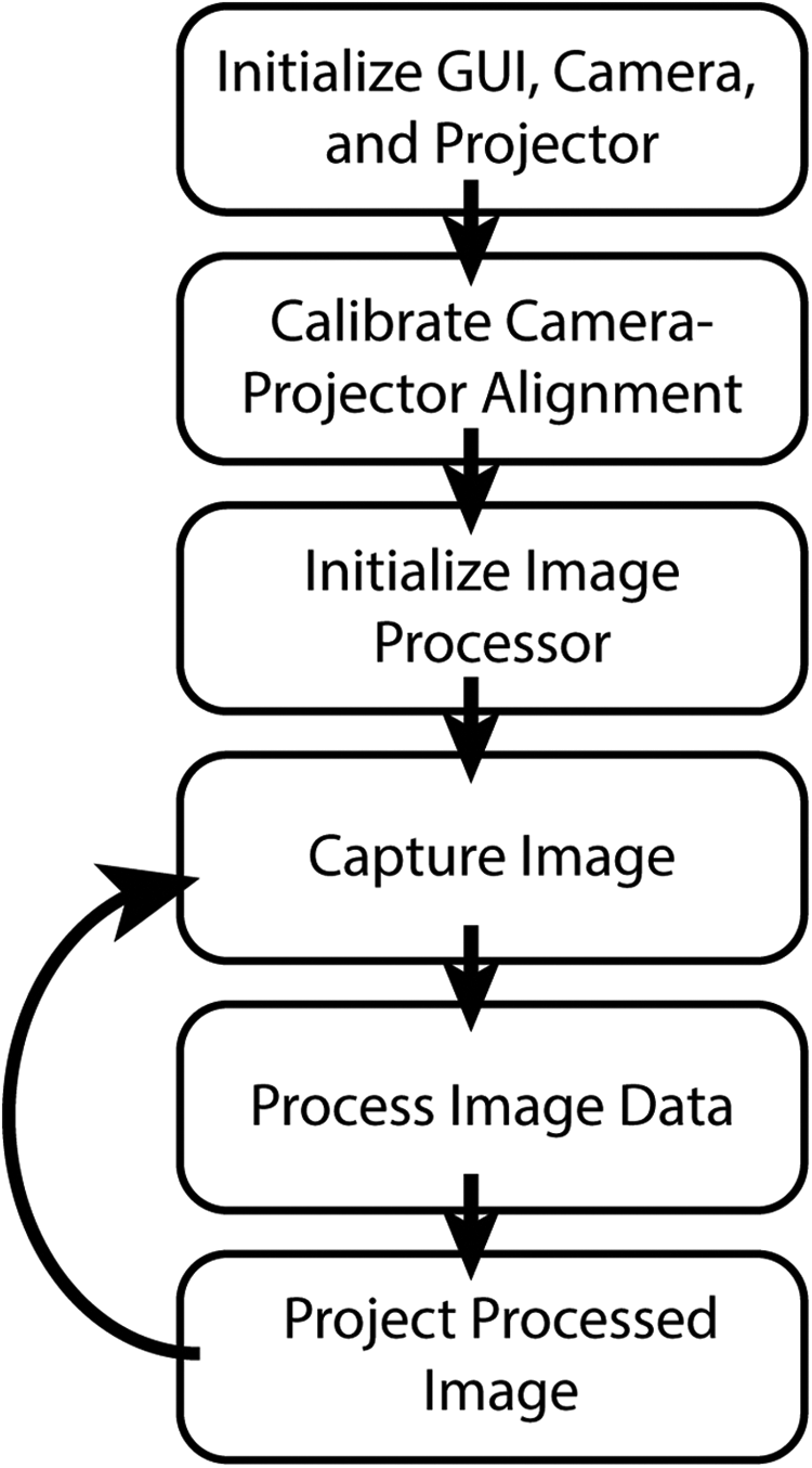
Workflow of optical projection of acquired luminescence (OPAL) control system.
Projector
The defining feature of this product comes in the form of a projected image through a projector with sufficiently high luminosity. After complete image processing, the ESB sends the processed data to the projector as a Java application run through MATLAB. To ensure proper alignment, the projector provides the ESB with a set of resolution and display parameters for accurate coregistration with received data.
Enterprise Service Bus
The ESB serves as both a router for all connections to and from components and a processing center to ensure that the data being routed to a component is compatible with that component. This allows for flexibility in exchanging different component models and ease of adding or removing components to the system. However, with each added component, the ESB gets increasingly complex internally as a result of managing so many connections. 8
Alignment Calibration
Since the camera and projector exist in separate coordinate systems and possess different FOVs, alignment calibration is necessary to match captured and projected images to the surgical field. To calibrate the camera–projector system, we picked the projector’s field as our reference frame and applied transformations to the camera’s frame to conform it to the reference frame. After characterizing every frame, all operations and calculations can be done in the reference frame, and results can then be transformed back to another frame if necessary.
Prior to use, calibration is performed through a series of steps that includes projecting and capturing images. Specifically, we use a basic shape (eg, square, circle, rectangle, etc) with a known set of coordinates and dimensions in the reference (projector) frame. The system then projects this shape onto a blank surface located at the same distance away as the operational subject. The camera captures a still image of the shape, which is processed to determine the same set of coordinates and dimensions of the shape in the camera’s frame. We found that shapes with discrete edges were most easily and accurately processed due to MATLAB’s included corner detection algorithms.
Accuracy of alignment of the projected image with detected signals was evaluated to verify calibration and evaluate object size limits of detection. To perform this method, the alignment calibration routine was evaluated first, as described earlier. Then an image with 9 dots, 5 of which had diameter 1.5 mm and 4 with diameter 1.0 mm (P0), was projected onto a flat, nonfluorescent surface. The camera was then triggered to capture an image of the FOV, including all dots projected in P0. This image (C1) was then thresholded and resized using calibration parameters and the resulting image (P1) projected. A second camera trigger captured this image (C2). This procedure was repeated 9 times each at 2 separate threshold levels, 80% and 99% using Otsu’s automated thresholding. The Euclidean distance between centroids and overlap correlation was compared for each dot in C1 and C2 to evaluate the accuracy of alignment based on location and size, respectively.
Image Processing
When applying only one threshold to the image, each pixel is contrasted with the entire image, sometimes causing important, lower fluorescence intensity signals to be drowned out by brighter ones nearby. Contrast limited adaptive histogram equalization (CLAHE) adjusts the contrast of an image by comparing first the histogram of small regions of the image to neighboring regions, and then sets a cutoff point at a certain level on the histogram. Any points above that cutoff are then redistributed across the entire histogram. After performing these contrast limitations, normal adaptive histogram equalization occurs and a transformation is applied across each region, based upon the distribution function of neighboring regions. 9 Thus CLAHE reduces the difference in contrast levels between smaller and larger areas of fluorescence, preventing the smaller areas from being drowned out. The difference in detail between simple global thresholds compared to using our CLAHE processing method is demonstrated in Figure 4A-C. User-based input allows real-time customization of image processing and display functions when desired (Table 1), accessed within the graphical user interface (GUI), including threshold sliders, colormap drop-down menus, and image capture button (Figure 4D).

Demonstration of on-the-fly automated thresholding for real-time projection of fluorescence information showing (A) raw fluorescence image data from the camera, (B) simple thresholding of A, and (C) contrast-limited adaptive histogram equalization threshold of A. D, A simplified graphical user interface for optical projection of acquired luminescence (OPAL) control and visualization with (1) threshold level slider, (2) 8-bit colormap selector, (3) color selector for binary threshold images, (4) image capture button, and (5) on/off button for real-time projection. Images of (left) raw camera capture and (right) processed image for projection are displayed on the controller’s computer monitor.
List of Control Options in the OPAL Graphical User Interface for User-Based Input.

Abbreviations: CLAHE, contrast limited adaptive histogram equalization; OPAL, optical projection of acquired luminescence; GUI, graphical user interface.
After applying the histogram equalization, a 2-dimensional (2D) median filter is applied to the image for additional noise reduction. Then the appropriate color map is applied to the image while the image data are converted to an appropriate data type for projection. Using information collected from the system calibration, the necessary frame transformation is applied to the image. This final processed image can then be projected as long as the projection setting is activated. 10 Otherwise, the processed image can still be previewed on the controller’s monitor in real time.
Intraoperative Demonstration of OPAL Imaging for Regional Lymph Node Dissection in Swine
All animal studies were conducted in accordance with protocols approved by the Washington University Animal Studies Committee. For all 3 studies, 35-kg female Yorkshire pigs were premedicated with atropine (0.04 mg/kg given intramuscularly) and a cocktail consisting of Telazol (tiletamine and zolazepam), ketamine, and xylazine (1 mL/50 lb [22.7 kg] of body weight given intramuscularly) prior to induction and maintenance of anesthesia with isoflurane (1% to 5% v/v in O2) by intubation. Vital signs were monitored during anesthesia. As a model of SLN biopsy for gynecologic cancer, 5 mg/mL indocyanine green (ICG) dissolved in sterile water (Sigma Aldrich, St. Louis, Missouri) was injected intradermally (0.1mL into 3 sites, bilaterally) of the vulva using an insulin syringe with a 29-gauge needle. For the SLN imaging in the second study, 5 mg/mL ICG was injected (0.3 mL) into the leg using an insulin syringe with a 29-gauge needle. To model SLN for head and neck cancer surgery, 5 mg/mL ICG was injected (0.3 mL) under the skin at the base of the chin as a single injection. All pigs were euthanized about 5 minutes postinjection by intravenous potassium chloride.
For intraoperative guidance, the OPAL system was positioned directly over the operating field, approximately 1 m above the skin surface. The handheld excitation light source was operated by an assistant, directed by the surgeon, to illuminate the region of interest without blocking the OPAL FOV. Automated system calibration was performed to ensure alignment of acquired and projected images. Acquired fluorescence images’ threshold level can be adjusted by the user via slider in GUI and resulting fluorescence mask displayed by projector onto the operating surface. Image mask was projected in green light for ideal visual contrast at 10 to 15 frames per second. Superficial inguinal lymph nodes were identified by transdermal fluorescence prior to incision and the region illuminated with green light. Guided by the location of green light, a single incision was made to expose the inguinal lymph nodes and complete the biopsy.
Results
Process Control and Accuracy
The basic functionality of our system is reliant upon accurate projection such that the projector illuminates the same location where the camera detects fluorescence. It is also vital for the calibration process to be in control. After each calibration, projected items should remain at the same locations even after halting and resuming the projection. That is, the calibration error should remain consistent within each calibration attempt.
Using a flat surface placed 1.00 m away from the lens of the projector and 1.11 m from the camera lens, we repeatedly captured a physical image and then projected that same image on top of itself. The calibration error measurement was taken as the distance from the center of the physical image to the center of the projected image. This process was repeated several times per sample. Each sample consists of the measurements taken after each independent calibration. With 95% confidence, the true mean calibration error was between 1.01 and 1.75 mm. The mean was tested using a 2-sided Student t test with an α level of 0.05 (Prism 5.0, Graphpad, San Diego, CA).
Accuracy of Alignment
Correlation between images was similar for both threshold levels (80% and 99%). However, the correlation for the 80% is lower than correlation for the 99% threshold levels. For each case, there is a variation in the Euclidean distance between centroids with the distance between centroids being better for the 80% than the 99%. This is due to the difference in thresholds resulting in smaller dots in the 99% with greater relative differences in centroids for each dot.
In addition, these results demonstrate the detection resolution of this system for fluorescent 1.5 and 3 mm diameter objects at a distance of 1 m. The accuracy of alignment is sufficiently high to accurately locate these objects within the operating field. Errors of size were due to overestimation by nearly double for 1.5 mm objects; however, accuracy of alignment was very high at both threshold levels (Figure 5).
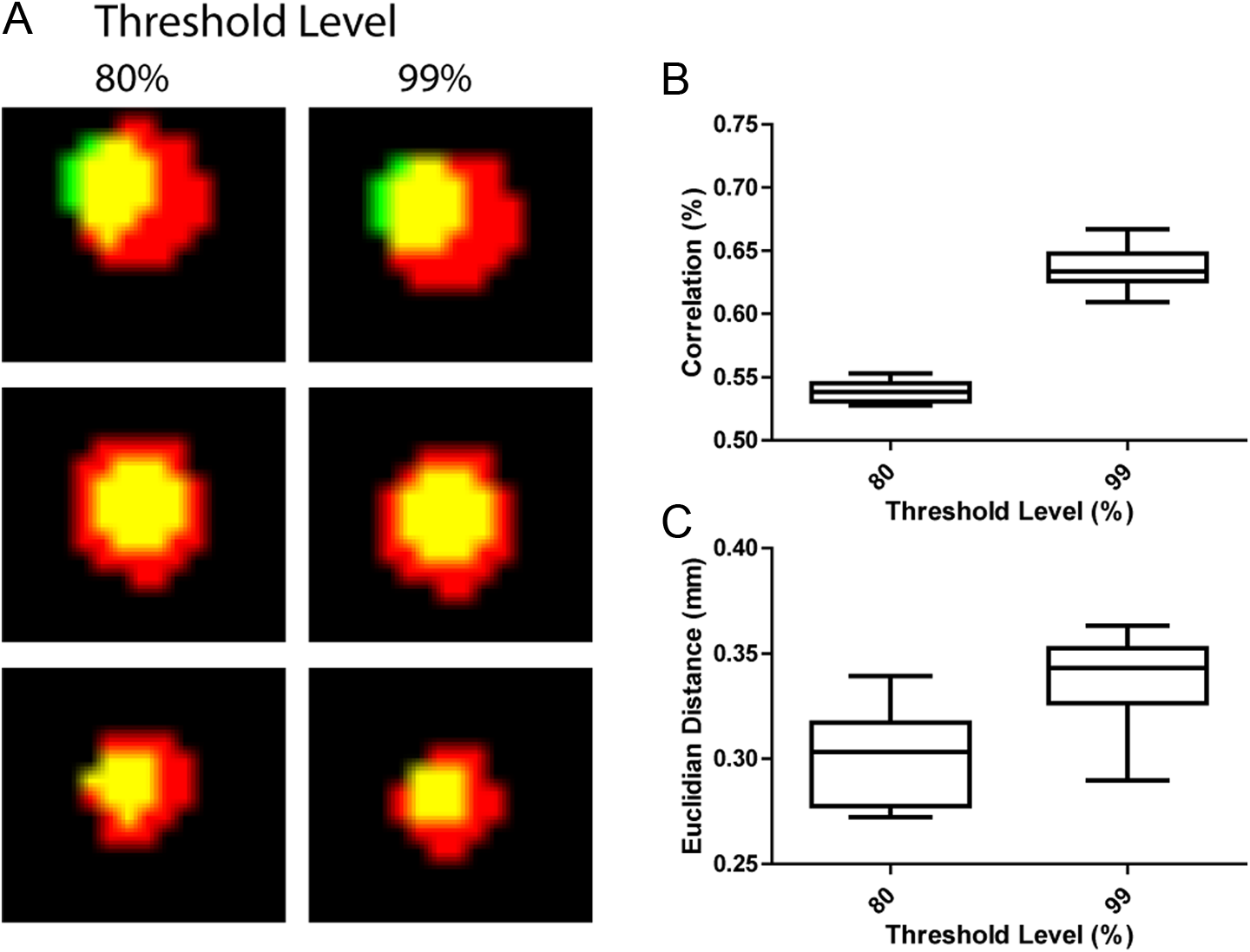
Analysis of alignment accuracy of optical projection of acquired luminescence (OPAL) system. (A), Overlay of image captures from initial projected spots (green) with thresholded (80% and 99% levels), reprojected spots captured at a distance of 1 m from OPAL system, demonstrating high resolution detection and accurate projection of 3.3 mm (top and middle rows) and 1.5 mm (bottom row) spots throughout the full field of view. Further analysis demonstrated relatively low correlation of localization (B) due to overestimation of spot size and high accuracy of alignment (C) as measured by the Euclidian distance between spot centroids.
Model of SLN Biopsy for Gynecological Cancer
There was visible on-field visualization of ICG transport to the regional lymph node after intradermal injection in vulva of female pig. Acquired fluorescence image information was projected onto the imaging field in monochrome green to facilitate localization and biopsy of the SLN. The right and left inguinal nodes were visualized and removed with guidance from OPAL technology. Green illumination tracked well with lymph node location to guide lymph node biopsy (Figure 6). This initial study illustrated the benefits of onfield visualization of the projected green fluorescence preincision, postincision, and postremoval. Fluorescence signal was confirmed to be localized to the lymph node and surrounding lymphatic vessels.

A, Intraoperative optical projection of acquired luminescence (OPAL) use identifying locations of inguinal lymph nodes after intradermal injection of indocyanine green (ICG) in vulva of female pig. (A), Transdermal fluorescence detection of inguinal lymph nodes (lower) and after initial skin incision (upper). (B), Representative raw fluorescence image capture from OPAL camera. (C), Resulting thresholded, binary image map created from B for projection onto surgical field.
Model of SLN Biopsy for Melanoma of the Lower Limb
After intradermal injection in the leg of the pig, there was definite on-field visualization of fluorescence from the ICG in the FOV preincision. To facilitate removal of the lymph node, the acquired fluorescence was projected in monochrome green onto the field. The fluorescence tracked well during removal of the tissue. Figure 7 illustrates the on-field visualization of the projected green light pattern after skin incision and elevation of suspected lymph node. Fluorescence signal was confirmed to be localized to the superficial lymph node and surrounding lymphatic vessels.

(A), optical projection of acquired luminescence (OPAL)-guided biopsy of superficial lymph nodes demonstrating indocyanine green (ICG) accumulation after intradermal injection in the lower hindlimb. (B and C), Representative raw fluorescence image capture and thresholded, binary image map for projection, respectively.
Model of SLN Biopsy in Head and Neck Cancer
After the pig was injected in the neck, there was strong on-field visualization of fluorescence preincision. The acquired fluorescence information was projected onto the imaging field in monochrome green. A gland in the neck was visualized and removed with guidance from OPAL technology. The gland was primarily composed of fatty tissue but was visualized with fluorescence due to the presence of lymphatic tissue. A small piece of tissue was removed which was green, verifying the presence of ICG. Figure 8 illustrates the on field visualization of the projected green fluorescence preincision and postincision. Fluorescence signal was confirmed to be localized to the lymph node with the presence of ICG. This tissue was highly fluorescent.

Optical projection of acquired luminescence (OPAL) highlighting of cervical lymph node after intradermal injection of indocyanine green (ICG) in the ventral to the mandible. A, A handheld near-infrared (NIR) light source illuminates the area of interest, exciting ICG fluorescence which is detected and reprojected by OPAL. B, ICG accumulation is confirmed by green color in lymph node, confirming accuracy and sensitivity of OPAL (C).
Discussion
Here we have reported a novel device for intraoperative fluorescence detection and fluorescence-guided SLN biopsy in large animals, replicating the clinical OR environment. Application of OPAL for detection of ICG fluorescence in lymph nodes and lymphatic vessels in large animal models of SLN biopsy demonstrates feasibility for intraoperative surgical guidance in human medicine.
Intraoperative optical imaging devices have now been developed for fluorescence imaging during surgical procedures. 3,6,11 –14 Optical imaging systems designed for use in the OR, such as ultrasound systems, have become less bulky over time. Devices can now be categorized as handheld or hands-free. Handheld optical spectroscopy (contact) and imaging (noncontact) devices are prevalent. Handheld devices are still encumbered with wired connections to light sources, computers, and monitors and require constant attention by the operating team. Hands-free devices, once positioned, require little interaction other than attention to adjacent display monitors, on the system itself or a nearby wall. Display of images on monitors may distract surgeons from focusing on the area of interest and compromise surgeons’ coordination, thus affecting surgical outcome. These limitations favor the development of real-time optical imaging systems for intraoperative procedures.
Reported hands-free fluorescence imaging systems collect and display fluorescence data in real time with anatomical image overlay, spectral deconvolution, background subtraction, and contrast enhancement. 2,6 Upcoming technological improvements promise head-mounted, see-through displays with stereoscopic vision to directly enhance the surgeon’s view of the surgical field with fluorescence information 15 though many hurdles must be overcome before this head-mounted technology will be adopted routinely by surgeons.
In contrast, OPAL system was mounted to an overhead surgical light for unobtrusive, intraoperative detection of ICG in tissues and lymph nodes. Green light signals rapidly alerted surgeon and surgical team to ICG location, even below the surface, without distraction of offset computer monitors, handheld cameras, or head-mounted devices and their associated connecting cables.
After site-specific injection, ICG traveled from site of injection to draining lymph nodes within minutes, enabling localization of the lymph node prior to incision in most cases. Indocyanine green has been shown to be equally or more sensitive and specific for SNL detection compared with radioactive colloid and blue dye injections. 1 While fluorescence detection is limited by tissue light attenuation to a few centimeters below the skin surface, lymphatic transport was visualized in real time. In addition, camera-based fluorescence detection is much more sensitive than naked-eye visualization of blue dye.
Using the handheld excitation device, sweeping the NIR illumination over the area of interest was effective in localizing ICG in tissue by fluorescence signals projected onto the skin or tissue surface. This was effective for noninvasive lymph node detection prior to incision in the groin (Figures 6 and 7) but not as good in deeper set cervical lymph nodes (Figure 8) due to depth-dependent light attenuation.
The projection of monochrome green was very strong, confirming locations of ICG for all 3 scenarios, aiding in discovery and resection of the lymph nodes. The OPAL projections successfully tracked, while tissues were moved and excised. While the projection of green light onto the FOV was successful in identifying regions of interest, this significantly altered the color and contrast of the tissues. On-demand or intermittent projection of fluorescence image data may be preferable to continuous projection. A delineation of color would provide more information on the presence of ICG than a single shade of monochrome green.
By projecting fluorescence that is darker in areas of higher ICG accumulation and lighter in areas of low ICG accumulation, the surgeon would be better informed on where to make the incision and which tissues to resect. This would also allow the surgeon to make decisions concerning the margins producing lower risk to damage adjacent vital structures. Alternately, brighter illumination sources could be used to fully illuminate the whole surgical field without affecting color temperature of surgical lighting. This would make the OPAL system truly hands-free. The applied calibration algorithm utilizes 2D imaging and shape detection algorithms using MATLAB functions. Feature detection and data projection display was excellent with detection of objects smaller than 2 mm and highly accurate size and colocalization of projected images on a flat surface. Alignment is likely to suffer in significantly nonflat environments as can be expected during surgery, requiring improvements in depth-of-field focus for camera and projection. Advanced calibration processes could include 3-dimensional imaging and depth perception to create much more detailed coordinate system (frame) characterizations and transformations and be integrated with surgical navigation systems. These improvements will be helpful in some ways, but may come at the expense of refresh rates. The system would benefit significantly if much of the foundation were written in a more efficient, lower level language such as C++.
Conclusion
Fluorescence imaging is used regularly in human medicine to assess patency of blood vessels and ureters during surgery. Near-infrared light (700-1000 nm) penetrates biological tissue much better than visible light, and background fluorescence is lower in this region as well. The human eye has highest sensitivity to green light (∼550 nm) and insensitive to light beyond 750 nm. 16 Digital camera sensors are much more sensitive to NIR light than human eyes. New high-intensity LED surgical lighting has optimal color rendering without the infrared component of previous halogen and other light sources. These factors led to the OPAL concept in which NIR fluorescence can be detected concurrent with surgical lighting then displayed directly on the operating field for high visual contrast.
Fluorescence image capture and direct projection with NIR fluorescent molecular probes will provide significant enhancements to current fluorescence guided surgery methods. Light beyond 750 nm is not visible to the human eye, so cannot be detected directly. Green light provides excellent contrast against red/white/yellow background within the abdomen. Projection of anatomically aligned fluorescence image data directly onto the surgical field will eliminate the need for digital monitor display during open surgery. This will make fluorescence information available to the entire surgical team.
Additionally, the OPAL system is similar in operation to other intraoperative imaging systems currently employed in the OR, allowing for a smooth transition into the OR. Because the OPAL system is primarily composed of the projector system, laptop, and NIR illumination source, the system is highly portable, providing easy implementation in the OR without disrupting normal surgical routine.
Footnotes
Acknowledgments
We are grateful to Michael Talcott, DVM, DACLAM and DCM Veterinary Surgical Services staff for technical assistance with animal studies.
Declaration of Conflicting Interests
The author(s) declared no potential conflicts of interest with respect to the research, authorship, and/or publication of this article.
Funding
The author(s) disclosed receipt of the following financial support for the research, authorship, and/or publication of this article: This study was supported by grants from the National Institutes of Health Office of Research Infrastructure Programs (K01OD010935) and the Barnes-Jewish Hospital Foundation BJHF-7583-55.