
Abstract
Purpose:
Scatter significantly limits the application of the dual-source cone-beam computed tomography by inducing scatter artifacts and degrading contrast-to-noise ratio, Hounsfield-unit accuracy, and image uniformity. Although our previously developed interleaved acquisition mode addressed the cross scatter between the 2 X-ray sources, it doubles the scanning time and doesn’t address the forward scatter issue. This study aims to develop a prepatient grid system to address both forward scatter and cross scatter in the dual-source cone-beam computed tomography.
Methods:
Grids attached to both X-ray sources provide physical scatter reduction during the image acquisition. Image data were measured in the unblocked region, while both forward scatter and cross scatter were measured in the blocked region of the projection for postscan scatter correction. Complementary projections were acquired with grids at complementary locations and were merged to form complete projections for reconstruction. Experiments were conducted with different phantom sizes, grid blocking ratios, image acquisition modes, and reconstruction algorithms to investigate their effects on the scatter reduction and correction. The image quality improvement by the prepatient grids was evaluated both qualitatively through the artifact reduction and quantitatively through contrast-to-noise ratio, Hounsfield-unit accuracy, and uniformity using a CATphan 504 phantom.
Results:
Scatter artifacts were reduced by scatter reduction and were removed by scatter correction method. Contrast-to-noise ratio, Hounsfield-unit accuracy, and image uniformity were improved substantially. The simultaneous acquisition mode achieved comparable contrast-to-noise ratio as the interleaved and sequential modes after scatter reduction and correction. Higher grid blocking ratio and smaller phantom size led to higher contrast-to-noise ratio for the simultaneous mode. The iterative reconstruction with total variation regularization was more effective than the Feldkamp, Davis, and Kress method in reducing noise caused by the scatter correction to enhance contrast-to-noise ratio.
Conclusion:
The prepatient grid system is effective in removing the scatter effects in the simultaneous acquisition mode of the dual-source cone-beam computed tomography, which is useful for scanning time reduction or dual energy imaging.
Keywords
Introduction
Cone-beam computed tomography (CBCT) using an X-ray source and a single flat panel detector has been widely used in a variety of applications in both radiology and radiation oncology. 1 –3 Recently, we developed and benchmarked a dual-source, dual-detector CBCT system, which has several advantages over the single-source CBCT system. 4,5 The dual-source CBCT can provide dual-energy imaging without the use of fast kilovoltage switching. 6 It may also reduce the total scan time required compared to current single-source CBCT systems and can be configured with 2 noncoplanar imaging chains to alleviate cone-beam artifacts. 7 A dual-source onboard CBCT system would also allow for simultaneous, orthogonal radiographs, or digital tomosynthesis, which have been shown to be highly useful for target localization in radiation therapy. 8 –10
Scatter has been a major problem with kilovoltage CBCT due to its large imaging field size. Scattered radiation detected by the imager can severely degrade image quality by inducing significant scatter artifacts, degrading the CT number linearity, and reducing the contrast-to-noise ratio (CNR). The effects of scatter are even more severe for dual-source CBCT due to the cross scattering between the 2 X-ray sources. Many techniques have been proposed to address the scatter issue. These techniques can be generally divided into 2 major types: (1) direct scatter reduction during image acquisition 11 –15 and (2) postscan scatter correction, in which scatter distributions are measured and/or modeled for each patient and subtracted after the scan. 16 –21 However, the efficiency of direct scatter reduction methods is frequently limited and often requires increased dose to the patient. Postscan scatter correction methods do not address the scatter-related X-ray quantum noise and can potentially degrade the CNR. 18,22 In addition, the traditional scatter correction methods using beam blocks typically require 2 scans to measure scatter and acquire image data separately. Consequently, patient dose is increased, and the accuracy of scatter correction is limited because scatter was measured under a condition different from the image acquisition condition. Recently, Wang et al developed a moving blocker system, 23,24 and our group developed a synchronized moving grid system (SMOG) 25,26 to combine both scatter reduction and scatter correction in the system. Our preliminary study using SMOG on a single-source CBCT system showed that it effectively removed the scatter artifacts and enhanced CNR while using similar imaging dose and scan time as a conventional CBCT system. 26 However, no such technique has been developed for the dual-source CBCT system. We recently developed an interleaved acquisition mode for the dual-source CBCT system to avoid the cross scatter between the 2 X-ray sources. 4 However, the method requires doubling of the scanning time and does not address the forward scatter issue.
In this study, we will develop prepatient grids for scatter reduction and correction for the dual-source CBCT system to address both the cross scatter and forward scatter issue. Static grids were attached to both X-ray sources during the image acquisition of the dual-source CBCT to provide physical scatter reduction. Similar to the SMOG system, image data were measured in the projection region unblocked by the grids, while both forward scatter and cross scatter were measured in the projection region blocked by the grid for postscan scatter correction. Complementary projections for both sources were acquired through multiple scans with grids offset by a distance equal to the grid interspace after each scan and were then merged to form complete projections for reconstruction. Experiments were conducted with different phantom sizes, grid blocking ratios, image acquisition modes, and reconstruction algorithms to investigate their effects on the scatter reduction and correction. The image quality improvement by the prepatient grids was evaluated both qualitatively through the artifact reduction and quantitatively through CNR, Hounsfield-unit (HU) value accuracy, and uniformity.
Materials and Methods
Experimental Set Up
Dual-source CBCT system
Our in-house-developed dual-source CBCT system consists of 2 X-ray tubes (Varian G-242; Varian Medical System, Palo Alto, California) and 2 flat panel detectors (PaxScan 4030CB; Varian Medical System) positioned orthogonally to each other, as shown in Figure 1. 5 In this system, both tubes and detectors are fixed, and the object being imaged is rotated by the rotational stage to acquire projections at different angles. The distance between each detector and the center of the rotational stage is 50 cm, and the distance between each X-ray source and the center of the stage is 100 cm, same as the set up in the clinical on-board imager system on a Linac. The size of each flat panel detector is 397 × 298 mm2 with a pixel pitch of 194 μm.

Experimental set up of the dual-source cone-beam computed tomography (CBCT) system.
Bowtie filters for full fan scans were attached to both X-ray sources. Two prepatient 1-dimensional grids made of 95WNICu tungsten alloy were attached in front of the bow tie filters for scatter reduction and scatter measurement. The thickness of each grid is 3.5 mm. Using the attenuation coefficient of tungsten at energy of 100 keV, it can be calculated that only 9.00E-14 of incident photons will pass through the 3.5-mm thick grid. Therefore, it is reasonable to assume that no primary photons will go through the blocked area of the grid. The grid blocking ratio is defined as the ratio of blocked area and unblocked area. In this study, grids with blocking ratios of both 1:1 and 2:1 were used to investigate the effects of grid blocking ratio on the scatter reduction and scatter correction. Similar to our previous studies, 4 120 kVp and 1 mAs (40 mA and 25 ms) per projection were used, and 554 projections per detector were acquired evenly spaced over 360°, giving a total of 1108 projections over 360°.
Acquisition modes
The following 3 acquisition modes were investigated in our study: simultaneous mode, interleaved mode, and sequential mode. In the simultaneous mode, the 2 X-ray tubes fire simultaneously and the 2 detectors record at the same time at each scan angle during a 1 rotation scan. In the interleaved acquisition mode, the tubes fire alternatively at each scan angle with the rotational speed of the stage reduced to half. In the sequential mode, the 2 X-ray tubes fire sequentially in 2 separate scans. The simultaneous mode has the shortest scanning time as well as the most significant scatter effects among the 3 acquisition modes. Details of the 3 acquisition modes were described in our previous studies. 4
Scatter Reduction, Correction, Penumbra Derivation, and Projection Merging
The grids attached to the X-ray sources provide physical reduction of the scatter by blocking part of the beams. The postscan scatter correction, penumbra derivation, and projection merging process are implemented in 5 steps as shown in Figure 2: (1) acquire blank scan (without phantom) and phantom scan with grids; (2) estimate the scatter distribution based on the measured scatter data from blocked areas in each blank scan and phantom scan projection using a cubic spline interpolation/extrapolation along the longitudinal direction; (3) subtract the scatter distribution from projection images for scatter correction; (4) negative logarithm transformation of the division of the scatter-corrected phantom scan projections and the corresponding scatter-corrected blank scan projections to derive image information in both the unblocked region and the penumbra region of the grids; and (5) complementary projections are acquired at each angle with the grid offset by a distance equal to the grid interspace after each exposure, and complete projection images are obtained by merging the scatter-corrected complementary projections. Note that step 4 derives the image information in the penumbra region of the grid by dividing the phantom scan by the blank scan in the penumbra region. To circumvent the “division by zero” problem in regions where the blank scan signal is minimal under the grid penumbra, we defined a “dead area” as a region with intensity less than a cutoff value, for example, less than 10% of the blank scan signal in the unblocked region. The dead areas were masked during the division process. Deriving image information in the penumbra region effectively reduced the blocked regions in the projections and is a key step for achieving complete projections without blocked regions after projection merging, as demonstrated in our previous studies. 25,26

An example to illustrate the scatter correction and projection merging procedure using grid of blocking ratio 1:1.
Due to the unavailability of a motor to automatically move the grid back and forth at each angle, the grid was static during each full rotation scan and was manually moved to complementary positions in-between scans in our experiments. The number of the scans needed is determined by the grid blocking ratio. For example, the 1:1 grid blocks half of the X-ray beam in each projection, and 2 projections are needed at each angle to obtain complete information. As a result, 2 scans are needed with the grid off set in-between scans.
The effect of scatter reduction only was also studied using the partially blocked projections directly for reconstruction without the scatter correction process. Basically, the scatter reduction only method uses the same process as shown in Figure 2 except skipping steps 2 and 3.
Reconstruction Algorithms
Both the Feldkamp, Davis, and Kress (FDK) back projection method and the iterative reconstruction with total variation (TV) method were used for CBCT image reconstruction to evaluate their effects on the image quality after scatter reduction and correction. 27,28 The FDK method reconstructs images by directly back project the filtered projections. The TV-based iterative reconstruction used in this study takes an adaptive approach proposed in the ASD-POCS (adaptive-steepest-descent projection onto convex sets) algorithm developed by Sidky and Pan. 28 A relative weighting factor between TV minimization and the data fidelity optimization is chosen as the initial starting point, and the algorithm will automatically and adaptively adjust the weighting factor during iterations to balance the effects of data fidelity optimization and TV minimization. The effectiveness of the algorithm is partially determined by the initially chosen relative weighting factor. However, the sensitivity of the final results to this weighting factor is less than that in the traditional TV iterative reconstruction methods with a fixed relative weighting factor for the TV minimization.
In general, the FDK method has high computation efficiency but is prone to noise and artifacts caused by undersampling. The iterative reconstruction with TV regularization has low computation efficiency but is effective in reducing the noise or streak artifacts caused by undersampling in the reconstructed images. However, the TV regularization term may also lead to blurriness of the image.
Evaluation Methods
The CATphan 504 (PhantomLab, Salem, New York) commonly used in CT QA (CT quality assurance) was used in this study to evaluate the image quality improvement with scatter reduction and correction. The size of the phantom was varied by attaching different annuli outside the CTP404 module of the CATphan to study the effects of the phantom size on the scatter reduction and correction efficiency. In this study, phantoms with the diameters of 15, 20, and 30 cm were investigated.
The effectiveness of scatter reduction and scatter correction was analyzed qualitatively by evaluating the artifact reduction and quantitatively by evaluating the CNR, the accuracy of reconstructed HU values, and the uniformity of reconstructed images. The CNR defined in our previous study was measured for 4 inserts of different contrasts in the CTP404 module using regions of interest (ROIs) drawn both in the inserts (red circles) and in the region adjacent to the inserts (yellow circles), as shown in Figure 3. 26
To evaluate the HU accuracy, the reconstructed pixel values were converted to HU values using a linear regression between mean reconstructed values of the 8 inserts in Figure 3 and their corresponding nominal HU values. The uniformity was evaluated in the uniformity module of the CatPhan. The uniformity index was obtained by calculating the standard deviation of the mean values of 5 ROIs (20 × 20 pixels) located in the center and boundary of the phantom, as shown in Figure 4.

Axial view of the CTP404 module with inserts of different contrasts. The red circles are the ROIs inside the inserts, while the yellow ones are the ROIs surrounding the inserts. ROIs indicates regions of interest.

Axial view of the conventional cone-beam computed tomography (CBCT) of the CTP486 uniformity module of the CATphan. Five regions of interest (ROIs) were defined (1 is in the center and the other 4 are at the edge) to calculate the uniformity of the image.
Results
Scatter Correction and Projection Merging
The profiles of the center column in a projection image are shown in Figure 5 to illustrate the scatter measurement, estimation, and correction process for blank scan and phantom scan projections. To avoid the penumbra effect of the grid, only the measured data inside the central one-third of each blocked region are used for scatter estimation. The average of these scatter data is used as the sampled scatter value at each blocked region, as shown in Figure 5. A cubic spline interpolation/extrapolation is carried out to estimate the entire scatter profile based on the sampled scatter values at different blocked regions in the projection.

An example illustrating the scatter estimation and correction process in (A) a blank scan and (B) a phantom scan. The blue solid line is the original 1-dimensional (1D) profile in the longitudinal direction in a blank/phantom scan projection. The star dots are the measured scatter in the blocked areas. The black line is the interpolated scatter distribution. The red solid line is final profile after scatter correction by subtracting the black line from the blue line.
The negative logarithm transformation was then applied to the division between the scatter-corrected phantom scan projections and the corresponding scatter-corrected blank scan projections to derive the image information in the partially blocked projection. Complementary partially blocked projections were added together afterward to obtain a complete projection at each scan angle. This process was repeated for different scan angles to obtain a complete set of scatter-corrected projections for CBCT reconstruction. Figure 6 shows an example of projection merging between 2 complementary projections.

Profiles extracted from complementary projections acquired using 1:1 grid after blank scan normalization and negative logarithm transformation. A, The red and blue solid lines were from 2 complementary projections acquired with the grid shifted by 1 grid interspace. B, Profile of the merged projection.
Effects of Acquisition Modes on Scatter Reduction and Correction
Figure 7 shows the images reconstructed by the FDK method using scatter reduction and correction for different acquisition modes. As indicated by the arrows, the scatter artifacts in the original images have been substantially reduced after scatter reduction and correction. Table 1 shows the change in CNR after scatter reduction and scatter correction for different acquisition modes. Four ROIs of different contrasts in Figure 3 were used to evaluate the effects.
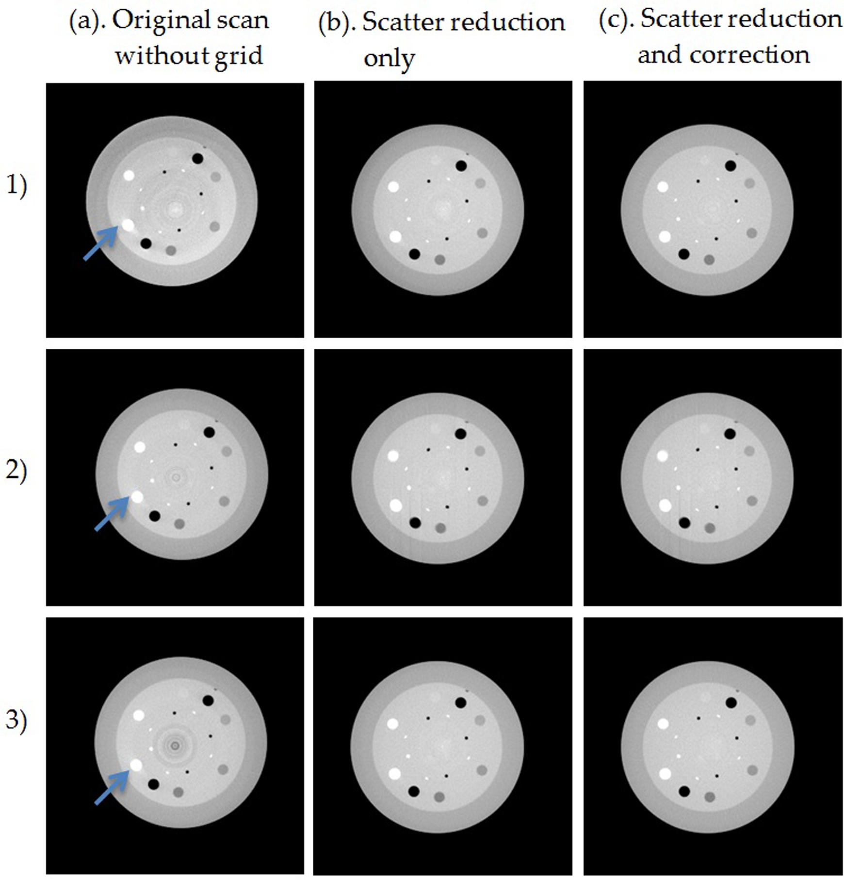
Reconstructed images of a CATphan of 20 cm diameter using (1) simultaneous, (2) interleaved, and (3) sequential acquisition mode. The 2:1 grid was applied for scatter reduction and scatter correction. From left to right column: (A) without grid, (B) scatter reduction only, and (C) scatter reduction and correction. Window width of 1000 HU and window level of −200 HU were used for all images. The Feldkamp, Davis, and Kress (FDK) method was used for reconstruction. HU indicates Hounsfield unit.
Comparison Between CNR Acquired by Simultaneous, Interleaved, and Sequential Modes.a
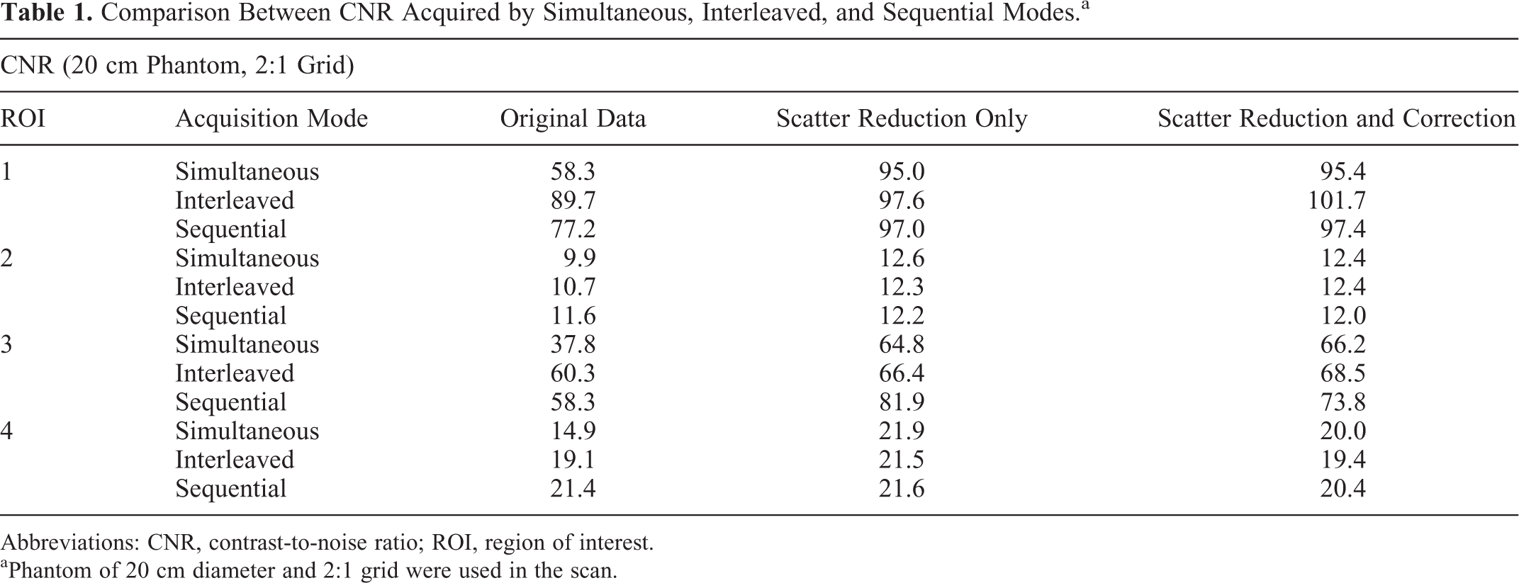
Abbreviations: CNR, contrast-to-noise ratio; ROI, region of interest.
aPhantom of 20 cm diameter and 2:1 grid were used in the scan.
Effects of Phantom Size on Scatter Reduction and Correction
Figure 8 shows the effects of phantom size on the scatter reduction and correction for the simultaneous acquisition mode. The FDK method was used for reconstruction. Scatter artifacts, such as streak artifacts indicated by the arrows, were reduced after scatter reduction and removed after scatter correction. Note that the bright ring in the peripheral regions of the images for the 30-cm-diameter phantom in Figure 8 is caused by truncation artifacts. 29,30 Table 2 shows the change in CNR after scatter reduction and scatter correction for different phantom sizes in the simultaneous acquisition mode.

Reconstructed images of a CATphan of 15, 20, and 30 cm diameters (from first to third row) acquired by simultaneous mode (dual source). The 1:1 grid was applied for scatter reduction and scatter correction. From left to right column: (A) without grid, (B) scatter reduction only, and (C) scatter reduction and correction. Display for first and second: window width of 1000 HU and window level of −200 HU were used. Display for third: window width of 2200 HU and window level of 100 HU were used. The Feldkamp, Davis, and Kress (FDK) method was used for reconstruction. HU indicates Hounsfield unit.
Comparison Between CNR in CBCT Images Acquired for Various Phantom Sizes.

Abbreviations: CBCT, cone-beam computed tomography; CNR, contrast-to-noise ratio; ROI, region of interest.
Effects of Grid Blocking Ratio on Scatter Reduction and Correction
Figure 9 shows the effects of grid blocking ratio on the scatter reduction and correction for the simultaneous acquisition mode using the FDK reconstruction method. As indicated by the arrows, the scatter-induced artifacts were substantially reduced by scatter reduction only and were removed after correction using both grids. Table 3 shows the change in CNR after scatter reduction and correction using 1:1 and 2:1 grids in the simultaneous acquisition mode.

Reconstructed images of a CATphan of 20 cm diameter acquired by simultaneous mode (dual source). The 1:1 (first row) and 2:1 grids (second row) were applied for scatter reduction and scatter correction. From left to right column: (A) without grid, (B) scatter reduction only, and (C) scatter reduction and correction. Window width of 1000 HU and window level of −200 HU were used for all images. The Feldkamp, Davis, and Kress (FDK) method was used for reconstruction. HU indicates Hounsfield unit.
Effects of Scatter Reduction and Correction for Different Grid Blocking Ratios.

Abbreviations: CNR, contrast-to-noise ratio; ROI, region of interest.
Effects of Reconstruction Algorithm on Scatter Reduction and Correction
The above-mentioned results were all generated by FDK reconstruction algorithm. Noise was increased in the scatter correction process, degrading the CNR especially for large phantom. Figure 10 shows the comparison of CBCT images reconstructed by different algorithms after scatter reduction and correction in the simultaneous acquisition mode. As shown in the figure, noise was reduced substantially by the iterative reconstruction method. Table 4 shows the CNR of the inserts reconstructed by different algorithms.

Reconstructed images of a CATphan of 20 cm diameter acquired by simultaneous mode (dual source). The 1:1 grid was applied for scatter reduction and scatter correction. Images were reconstructed from the Feldkamp, Davis, and Kress (FDK) method (first row) and iterative method (second row). From left to right column: (A) without grid, (B) scatter reduction only, and (C) scatter reduction and correction. Window width of 1000 HU and window level of −200 HU were used for all images. HU indicates Hounsfield unit.
Effects of Reconstruction Algorithms on Scatter Reduction and Correction.

Abbreviations: CNR, contrast-to-noise ratio; FDK, Feldkamp, Davis, and Kress; ROI, region of interest; TV, total variation.
Improvement in the HU Accuracy by Scatter Reduction and Correction
Table 5 shows the calibrated HU values in the reconstructed CBCT images of a phantom of 20 cm diameter acquired with the 1:1 grid and simultaneous acquisition mode.
HU Accuracy in Reconstructed CBCT Images of Phantom of 20 cm Diameter Acquired With the 1:1 Grid and the Simultaneous Scanning Mode.

Abbreviations: CBCT, cone-beam computed tomography; HU, Hounsfield unit; ROI, region of interest; LDPE, low density polyethylene; PMP, polymethylpentene.
Improvement in the Image Uniformity by Scatter Reduction and Correction
Table 6 shows the uniformity index of the reconstructed CBCT images after scatter reduction and scatter correction. A phantom of 20 cm diameter, 1:1 grid, and simultaneous acquisition mode were used for this study.
Uniformity Index of 3 Image Sets: Original CBCT, CBCT Reconstructed With Scatter Reduction Only, and CBCT Reconstructed With Scatter Reduction and Correction.a

Abbreviation: CBCT, cone-beam computed tomography.
aThe phantom of 20 cm diameter, 1:1 grid, and simultaneous mode were used.
Discussion
Effects of Scatter Reduction and Correction for Dual-Source CBCT
All the above-mentioned studies showed that scatter artifacts in the CBCT acquired in the simultaneous acquisition mode were reduced by scatter reduction and were removed by the scatter correction method. Scatter reduction alone was shown to enhance CNR, while adding scatter correction may enhance or degrade CNR due to the increase in both the contrast and the noise in the scatter subtraction process. Note that in Table 1, high-density inserts, such as ROI3 (HU = 990) and ROI4 (HU = 340), had more decrease in CNR after scatter correction alone in the sequential mode compared to low-density inserts, such as ROI1 (HU = −1000) and ROI2 (HU = −35). This may be due to the fact that high-density inserts generate more scatter and correspondingly higher noise in the scatter signal. As a result, the effect of noise enhancement is more prominent during the scatter subtraction process leading to poorer CNR for high-density inserts in the reconstructed images.
The HU accuracy was improved by both scatter reduction and scatter correction. Combining scatter reduction and scatter correction achieved the best accuracy for HU values. The image uniformity was also improved by both scatter reduction and correction due to the reduction and removal of the cupping artifacts caused by scatter, respectively.
Effects of the Acquisition Modes of the Dual-Source CBCT
Comparing different acquisition modes, the original images from the simultaneous acquisition mode had the lowest CNR due to the cross scatter between the 2 X-ray sources. Interleaved mode had similar CNR as the sequential mode due to the avoidance of cross scatter during the scan. For all the 3 modes, CNR increased after the scatter reduction but slightly decreased for some inserts after the scatter correction alone due to the increase in noise in the scatter subtraction process. The simultaneous mode had the largest enhancement of CNR and achieved similar CNR as interleaved and sequential modes after scatter reduction and correction. This showed that the prepatient grid system was effective in reducing and correcting both forward scatter and cross scatter in the simultaneous acquisition mode, which is the most preferable among the 3 acquisition modes due to its scanning efficiency.
Effects of the Phantom Size
Regarding the effects of the phantom size, CNR decreased substantially as phantom size increased due to the increase in scatter, as shown in Table 2. Same as before, scatter reduction increased the CNR while scatter correction decreased the CNR slightly for some inserts. Combining scatter reduction and correction led to enhancement of the CNR. Note that even though scatter reduction and correction can effectively remove the scatter to obtain similar contrasts for different phantom sizes, the CNR after scatter reduction and correction for a larger phantom was still substantially lower than that for a smaller phantom. This is because the higher scatter signal generated by the larger phantom corresponds to higher magnitude of noise, which leads to higher noise after scatter subtraction and therefore lower CNR in the scatter-corrected CBCT images.
Effects of the Grid Blocking Ratio
Regarding the effects of the grid blocking ratio, results showed that higher grid blocking ratio achieved substantially more enhancement of CNR than lower grid blocking ratio due to the more drastic physical reduction in the scatter. It can also be intuitively understood that grids with a high grid blocking ratio blocks out more primary beams and shapes the cone beam into multiple fan beams, which effectively reduces the scatter and enhances CNR. However, on the other hand, higher grid blocking ratio requires more complex imaging procedures and image processing to obtain complete projection information of the patient. Thus, higher grid blocking ratio may be more preferable for imaging larger patients with severe scatter effects to balance between efficiency and image quality in the dual-source CBCT.
The effects of phantom size and grid blocking ratio can also be explained mathematically as following: denote variables S and P as the mean values of the detected scatter and primary signals after scatter reduction by the grid, respectively; denote variable nc as the noise of the line integral image after scatter reduction and correction; and then the variance of nc can be calculated as follows, as explained in the article published by Zhu et al
22
:

A smaller phantom or higher grid blocking ratio will lead to lower S/P due to the smaller imaging scatter volume. Based on this equation, it will lead to lower var(nc) and higher CNR in the reconstructed images after scatter reduction and correction, which is consistent with the above-mentioned results and discussion.
Effects of Reconstruction Algorithms
Results showed that the iterative reconstruction with TV regularization achieved substantially higher CNR than the FDK method in the original CBCT images acquired without grids due to the noise suppression by the TV algorithm. The enhancement of CNR by scatter reduction and correction was also more dramatic for the iterative method than the FDK method.
Limitation of the Current Study
In this study, both grids were attached statically to the 2 X-ray sources during the scan due to unavailability of motors to move the grid during the scan. As a result, multiple scans were acquired to obtain complete projection information, which limited the scanning efficiency of the dual-source CBCT system. In the future, dual motors will be developed to move both the grids back and forth at each angle to acquire complete projections during 1 scan, similar to that proposed in the SMOG system. 26 With the moving grid system, the dual-source CBCT can potentially reduce the scanning time to half of that of a single-source CBCT or perform dual energy imaging within 1 scan with minimal scatter effects from both forward scatter and cross scatter.
Conclusion
A method using prepatient grids has been developed for scatter reduction and scatter correction for a dual-source CBCT system. Results showed that the method effectively removed scatter artifacts, enhanced CNR, and improved the HU accuracy and image uniformity in the simultaneous acquisition mode. The simultaneous mode achieved comparable CNR as the interleaved and sequential modes after the scatter reduction and correction. Increasing the grid blocking ratio led to more physical scatter reduction and as a result less scatter artifacts and higher CNR. Increasing the phantom size led to more scatter generated and lower CNR after scatter reduction and correction. The iterative reconstruction with TV regularization was also effective in reducing the noise caused by the scatter correction algorithm to enhance the CNR.
Footnotes
Authors’ Note
All authors certify that this article has not been published in whole or in part nor is it being considered for publication elsewhere.
Declaration of Conflicting Interests
The author(s) declared no potential conflicts of interest with respect to the research, authorship, and/or publication of this article.
Funding
The author(s) disclosed receipt of the following financial support for the research, authorship, and/or publication of this article: This work was supported by the National Institutes of Health under Grant Nos. R01-CA166948 and R01-CA184173, with further support provided by a research grant from Varian Medical Systems.