
Abstract
Objectives
Irreversible Electroporation (IRE) is a non-thermal minimally invasive cancer therapy used in the treatment of liver tumors. However, the therapy entails an electrical current flux which can be high enough to cause a noticeable temperature increase. Therefore, the analysis of the heat distribution is important: during any IRE treatment, the target area is intended to be treated with non-thermal effects, where existing thermal effects should not damage nearby sensitive structures. This article aims to compare the established two parallel needles electrode setup, used by FDA-approved electroporation delivering devices, to a single needle, multiple electrode prototype design.
Methods
Levels and distributions of the temperature at different distances from the applicators during an IRE liver treatment were investigated. The prototype results were collated with already published in-vivo data. All electrode configurations were analyzed numerically in COMSOL Multiphysics for different pulse protocols.
Results
The extension of coagulation necrosis predicted by the model matched available in-vivo data. While the maximum average temperature during pulsation was higher for the prototype (74 °C) than for the two-needle IRE setup (57 °C), the thickness of the coagulation necrosis around the conductive electrodes was in the same range for both configurations. However, the location differed completely: the necrosis engendered by the prototype was located inside the tumor, while the two-needle IRE setup created necrosis outside the tumor, potentially closer to sensitive structures.
Conclusion
The results highlighted the importance of heat distribution analysis for the design of new IRE needles as well as for IRE treatment planning. Proper analysis ensures that the non-thermal effects are maximized while minimizing any potential thermal damage to surrounding sensitive structures.
Keywords
Introduction
Cancer is the group of diseases caused by an uncontrollable growth of abnormal cells due to certain changes (mutation) in the DNA within the cells. 1 Carcinoma is a type of cancer that starts in epithelial cells, which make up the skin or the tissue lining organ such as kidney or liver. 2 With about 8.2 million cancer-related deaths per year, liver cancer represents 9% of mortality burden. 3 Moreover, the liver is one of the most common sites for metastasis. 4 Therefore, strategies for the treatment of liver lesions are paramount in the management of oncological patients.
Several treatments can be used to cure or reduce the size of liver tumors, depending on the stage and the type of the patient's individual tumor. Liver transplantation is a treatment, where the patient receives a full or partial donor liver. Liver surgery, in which a part of the organ is removed, or chemotherapy, which can be used alone or combined with other therapies. Besides these classical treatments, minimally invasive ablation techniques may be used to kill the abnormal tissue on location. 5 Such tumor ablation techniques can be divided into two categories: thermal ablation, where high temperatures are used to destroy the tumor tissue, eg Radiofrequency Ablation 6 [RFA] and Microwave Ablation 7 [MWA] and cryoablation which uses low temperature for the same purpose. In addition, Magnetic nanoparticle hyperthermia involves introducing magnetic nanoparticles into tumor tissue and subjecting them to an alternating magnetic field. This field induces the nanoparticles to generate heat, selectively destroying tumor cells while sparing healthy tissue. The technique is further enhanced by increased particle diffusivity during tumor ablation. 8 These thermal ablation techniques have several advantages, being minimally invasive and offering treatment with minimal damage to healthy tissue. While these techniques have high success rates, they are less effective for larger or strategically placed tumors and carry risks of incomplete ablation and recurrence.
Non-thermal ablation modalities are based on electroporation [EP], such as Irreversible Electroporation [IRE] and Electrochemotherapy [ECT]. IRE has been introduced as a promising non-thermal ablation technique that uses electric voltage DC pulses to create an electric field that induces cell death. 9 Compared to thermal ablation techniques, IRE has the critical advantage of preserving vulnerable structures. Also, IRE has no significant effect on connective tissue, which implies that ablation of tumors adjacent to nerves and bile ducts is possible. Furthermore, IRE can induce both apoptotic and necrotic cell death, its ability to promote apoptosis over necrosis, can lead to a better liver repair response10,11 that can facilitate the migration of immune cells in the ablation site, thus enhancing the development of an immune response against the tumor. 12 Therefore, the IRE treatment modality is typically used in cases of tumors near larger vessels. 13
High voltage electric DC pulses generate field strength high enough for the biological effect of irreversible EP. It was currently approved that IRE modality devices such as AngioDynamics NanoKnife® (Latham, New York) operate through a voltage generator up to Umax = 3 kV 13 with an operating current ranging between 20 A to 50 A. Electrodes are placed into the targeted tissue. 14 The electric field strength E has the highest value Emax directly on the surface of the parallel needle electrodes. During the IRE procedure, the target field strength Etarget between the electrodes should be in the range of 1.0 to 2.0 kV/cm15,16. This often-stated field strength must be distinguished from the real threshold of irreversible EP: Eirrev in liver tissue ranges from 600 to 800 V/cm (depending on i. a. the pulse protocol and the tissue type).14,17,18 As E decreases with the distance from the electrode, an ablation zone is created in the volume where the electric field strength is between Eirrev and Emax, the shape of this ablation zone, simplified often as spherical or peanut-shaped under idealized conditions, but can vary depending on the distance between the electrodes, 19 and the electrode configuration.20,21 Cells outside the ablation zone could still experience electric field E, but with a field strength below Eirrev, they are not irreversibly electroporated and are still alive. Therefore, a typical distance d between 1 cm to 2 cm is mostly used for placing the needle electrodes.
AngioDynamics NanoKnife® consists of up to six linear needle shaped electrodes that are placed around the tumor to create the electrical fields that are intended to kill the tumor. 9 In a typical procedure, these needles are inserted individually one by one with CT guidance, which is a highly time-consuming process. The electrode exposure can vary between 5 mm and 40 mm, 19 and is manually adjusted depending on the size of the tumor. Relative placement errors are known to be a potential cause of incomplete ablations. 22 Although up to six electrodes can be connected to the device, the electroporation itself is done between every pair of two electrodes consecutively.23,24 Therefore, this technique with two straight needle electrodes is referred to as “classic IRE setup” or “classic IRE electrodes”.
ECT is another EP-based treatment modality. Due to the reversible electroporation, which happens when a cell is exposed to a sufficiently intense electric field, pores in the cell membrane will be temporary formed leading to the permeabilzation of the cell membrane (the range for the threshold Erev is around 400 to 600 V/cm, below Eirrev). 25 This enables the cells to more effectively absorb pharmaceuticals, including chemotherapeutic drugs. 26 Thus, the cells are killed by the drug, not by the electric treatment or the EP itself. ECT is established for skin cancer (malignant melanoma), 27 and it is headed for becoming established for tumors treated via percutaneous methods as well.28,29
A new promising EP-ablation device has been set recently, referred to as “IRECT prototype” in the following, 30 (IRECT is the previously given name of the device 31 which expresses both effects, IRE and reversible electroporation are intended to affect the tissue simultaneously during the same treatment). The device consists of a single needle with four expandable electrodes that are placed inside the tumor. This design places five independently connected and individually wired electrodes with a single needle insertion, streamlining the procedure with fewer needle placements and subsequently reducing radiation exposure by minimizing the need for additional CT scans per electrode insertion. Also, possible inaccuracies in relative needle positioning can be reduced. The device can also be used for adding ECT to the treatment: Through the hollow expandable electrodes chemotherapeutic drugs can be injected directly in the zone of reversible EP. 30 In this way, the ablation volume can be nearly doubled. 31
Although IRE is a non-thermal ablation technique, 32 Joule heating will still be present and cause an increase in temperature during the procedure. 33 During the planning of an IRE treatment, multiple parameters must be considered to determine the size and shape of the ablation zone such as the electrode geometry (size, shape, placement) and pulse parameters (voltage, duration, wave form). Several studies have investigated the thermal effects of IRE and found that these parameters could lead to an increase or a decrease in thermal effect during IRE treatment.34,35 It was shown that numerical simulations have the ability to evaluate and predict current, electric field and temperature under the influence of electric pulse and electrode configuration.36,37
The objective of the research is to investigate the cited IRECT prototype in context of temperature distribution on a classic IRE setup. First, we numerically investigated the temperature distribution in swine liver tissue using the classic IRE needle configuration (two parallel unipolar electrodes) to prove the closeness to reality of the created simulation model by comparing the findings to those reported in literature. Based on this literature evaluated simulation, firstly the IRECT prototype model was studied to determine the temperature distribution using the same pulse protocol as the classic configuration, in the aim to compare both configurations under conditions typical of clinical practice. Secondly, we set up a simulation based on a previously published in-vivo animal study that used the IRECT prototype on swine liver tissue. 31 The simulation results were compared to the actual pathology and CT images. Finally, all results were put into context and assessed. The importance of simulations in predicting the outcome of electroporation procedure and the relative importance of thermal effects was highlighted.
Materials and Methods
The design for the electrodes used in this study was made using a computer-aided software (Solid Works 2019) with a live link to a finite element method (FEM) simulation software (COMSOL Multiphysics 5.5; COMSOL AB, Stockholm, Sweden).
For the two different electrode configurations that were considered in this study, ie the classic IRE needle and the IRECT prototype configuration, a common input model (described below) was used.
Common Input Model
A sphere having the same volume was taken to represent the liver in both models. To quantify the effect on temperature of the distance between the liver boundary and the needle, different radii of the sphere have been tested (25, 35, 50 mm). These tests showed a difference below 0.5% in the current and a below 1% in temperature and 25 mm was taken for both configurations to help keeping the computing time within reasonable limits.
In both models, the metal part of the needle is made of stainless steel. The properties are shown in Table 1.
Stainless Steel Properties.

In both electrode configurations, insulation was included as Polyvinyl chloride (PVC) having the following properties, see Table 2.
Polyvinyl Chloride Properties.

The tissue was defined as swine liver. The electrical conductivity of the liver was taken as a stepwise function with transition located at 500 [V/cm], starting at 0.1 [S/m] and ending at 0.237,
44
as shown in equation 1
Pig Liver Properties.

The heat transfer within the biological tissue is described by the bioheat transfer equation: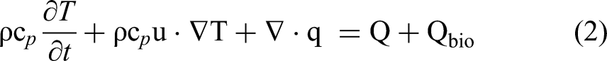


Where α is the probability of cell death, A the frequency factor, ΔE is the activation energy, R is the universal gas constant, and T is the absolute temperature, and Ω is the non-dimensional damage parameter. 47
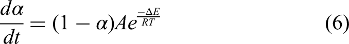
The values used to represent the properties of the bio heat and thermal damage equations are shown in Table 4 where the blood perfusion rate was set to zero in the region where the tissue was irreversibly electroporated. 48
Parameters of the Bio Heat Equation.
For electric currents, the surface of the liver was defined as an insulation boundary. Terminal boundaries were set for the electrodes to deliver the voltage. With the equation of current conservation represented by:


Where
The heat source due to joule heating was defined with the following equation:

Where
The pulses were defined as a rectangular waveform with characteristics (pulse length, pulse interval) that were mentioned later in the text. Quadratic elements were taken for the domain discretization. The electrical properties and values of all segments in the numerical model for the liver and electrodes are mentioned in Tables 1 to 3 including the electrical conductivity and permittivity values.
Classical Two Needle IRE Setup
The design of the electrode was taken to reproduce the classic needle setup.
The geometry consisted of two parallel electrodes having a diameter of 1 mm and an electrode exposure of 15 mm (active part). Both electrodes were insulated with PVC with a thickness of 0.1 mm and a length of 9mm; the tip of the electrode had a height of 2 mm. The dimensions were measured directly from the electrode shown in Figure 1a. The distance between the two electrodes was set to 1.5 cm. Several simplifications were taken into consideration in this model. The geometry was cut at the level of intersection between the liver and the electrodes. An effective heat flux 

a. Nano knife probe, b. electrode model, c. Symmetrical geometry.
Symmetry of the geometry was also exploited by halving the computational domain, as shown in Figure 1c.
Electric potential boundary conditions were set for the active part of the electrodes, one at zero potential and the second at V0, defined as:
V0= 1500*int(t) [V] (14)
The mesh was built using a tetrahedral shape for both liver and electrode domains. The final mesh was chosen based on a mesh convergence study, balancing computing time and accuracy of the results. The chosen mesh had a maximum element size of 4.06 mm and a minimum element size of 0.1 mm which resulted in 42375 elements.
IRECT Prototype Applicator
The IRECT prototype applicator is a needle shaped probe with four expandable electrodes for percutaneous image-guided IRE in liver. The needle shaped applicator has a central shaft with a thickness of 3.3 mm. At the top of the central shaft there is a 9 mm long conductive part and a tip with 2 mm height. The remaining length of the central shaft is insulated with Polyvinyl chloride (PVC). As for the satellite electrodes, they pass through the central shaft and can be expanded to the outside once in the tumor. Each satellite probe has a 0.6 mm diameter with 9.8 mm long conductive part. PVC is also used for the insulation of the satellite probes. The satellite electrodes deploy in a radius of 35 mm. Due to the complexity of the electrode configuration at the location where the expandable electrodes and the main shaft intersect, the geometry below this intersection is excluded from the computational domain, see Fig 2d. Also, a quarter symmetry is used in order to reduce the computing time as shown in Figure 2.

a. closed IRECT probe, b. deployed IRECT probe, c. IRECT probe model, d. quarter - symmetrical Geometry.
To effectively model the heat removed by conduction through the electrode shaft, a heat flux is defined at the lower boundary of the electrodes (main shaft and satellites), as described earlier for the classical setup.
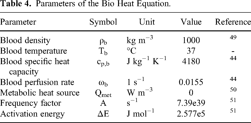
Also for this model, a mesh convergence study was performed. The mesh was divided into three domains, as shown in Table 5. The chosen mesh resulted in 391366 elements.
Mesh Size for the Liver and Electrode.
A corner refinement node was introduced between the main shaft and the insulation to describe sharp corners accurately. Boundary layers were added for the main shaft and the liver.
Two simulations were done for the IRECT prototype. For both simulations, the same boundary condition and mesh were used. The main shaft was set to zero potential and the four electrodes at V0, ie the input voltage delivered through the electrode.
For the first simulation, the input voltage V0 was 1500 V with 70 pulses, 100 microsecond pulse length, 1 Hz in sync with the heart rate, one pulse per second. This simulation was done for comparison with the classical two-needle IRE simulation mentioned earlier.
The purpose of the second simulation was to compare with a previous successfully completed and published animal experiment involving swine liver tissue. 31 These experiments were conducted on ten domestic pigs. IRE pulse protocol was applied in the liver of the pigs, using four pulse trains. Each pulse train consisted of 30 pulses with pulse length of 100 microseconds and 20-s pause between each pulse train. The input voltage changed for each pulse train with 500 V for the first 30 pulses, 1000 V for the second pulse train and 1500 V for the last two pulse trains. contrast enhanced CT and MRI were conducted after the procedure and ablation volumes were evaluated histopahtologicaly. 31 In our simulation, we used the data from this published study to replicate the conditions and compare our simulated results with the experimental outcomes.
Results
Classical Two Needle IRE Setup
The simulation was performed with an input voltage of 1500 V, a constant pulse width of 100 microsecond, 70 pulses and 1 s pulse interval. The temperature was measured at different locations within the geometry of the model.
By applying 70 pulses with 1500 V input voltage, the highest overall average temperature calculated across the active surface of the electrode was achieved at the end pulse and had a value of 57 °C with an average current of 0.002 A concentrated on the tip of the electrode, and a thermal ablation volume of 1.65 cm3. The temperature rose at the beginning of each pulse and dropped at the end of the pulse until it reached the maximum value before dropping after the last pulse due to tissue cooling effect as depicted in Figure 3.
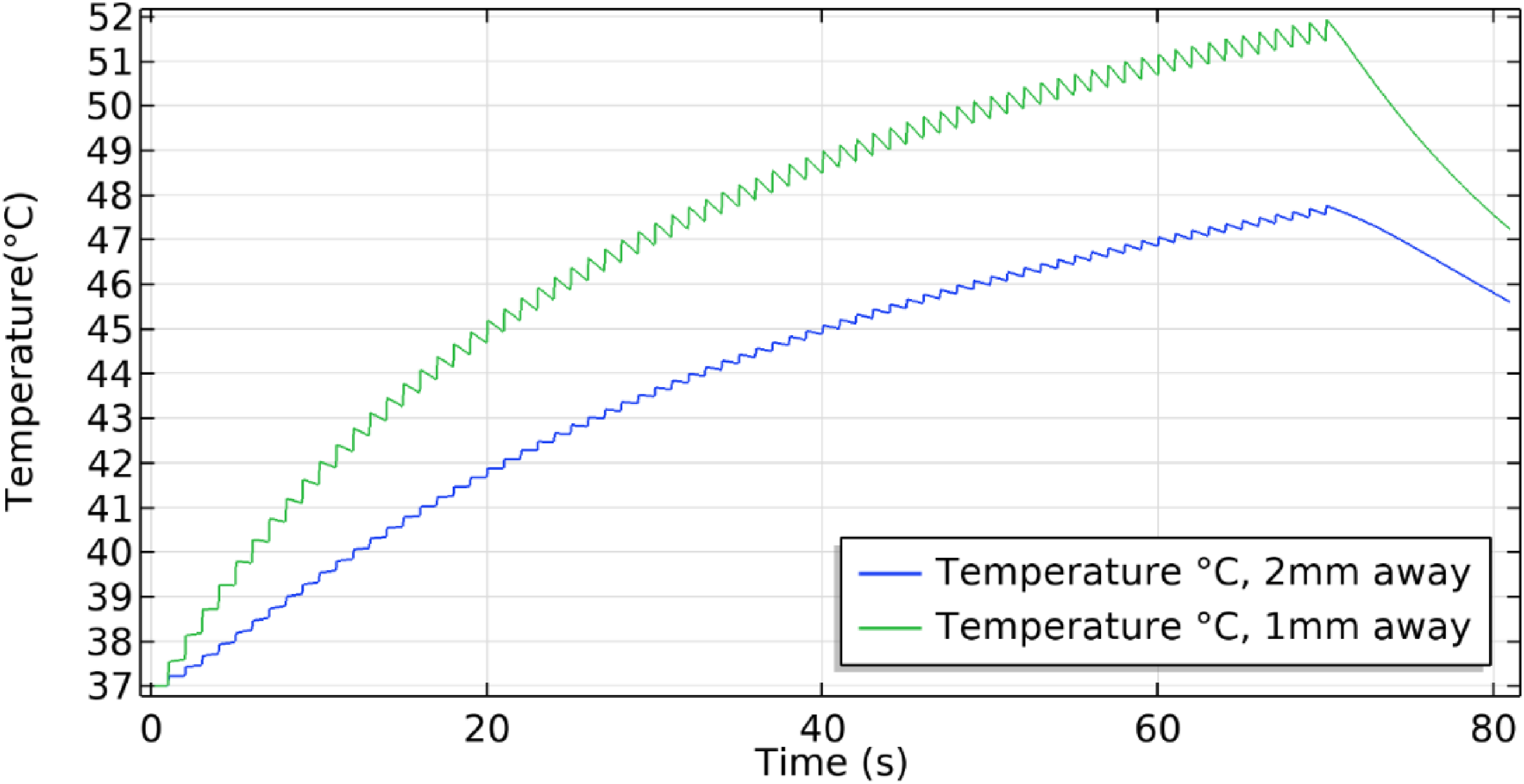
Maximum temperature plot along the classic needle setup where the green curve is at 1 mm, blue is at 2 mm distance from the central electrode.
The temperature was recorded at three different positions with respect to the zero potential electrode, at half length of the shaft. Starting at the electrode surface, the maximum temperature achieved had the value of 55.2 °C and it dropped when moving further away: at 1 mm, the maximum temperature recorded was 51.9 °C and at 2 mm the maximum value was 47.7 °C as shown in Figure 3.
IRECT Prototype
By applying the same pulse and input voltage used in the classical two needle IRE electrode, a simulation was conducted for the IRECT prototype. The computation time was set to 81 s and the value of temperature was recorded at different positions within the geometry.
Temperature measurements were taken at half-length of the central shaft, where the maximum temperature was expected. The plot of temperature was taken in the vicinity of the central shaft, and the highest temperature observed was 74 °C with an average current of 0.0105 A, and a thermal ablation volume of 2.43 cm3, which decreased as the distance from the central electrode increased. At a distance of 1 mm, the maximum temperature recorded was 58 °C, and at a distance of 2 mm, the maximum temperature observed was 49 °C. The data represented in Figure 4. As for the satellite electrode, the maximum value of temperature was recorded at the surface and had a value of 48.1 °C with a behavior similar to the central electrode: the temperature rose at each pulse and dropped by a small percent at the end of each pulse. The temperature at 2 mm distance from the expandable electrode was also recorded. The maximum value recorded at this second position was 39.4 °C as shown in Figure 4.

a. Temperature plot for IRECT prototype where the green curve is at 1 mm distance from the central electrode, blue is at 2 mm b. Temperature plot for IRECT prototype where the black curve is at 1 mm distance from satellite electrode, red is at 2 mm.
Figure 5 shows a cross sectional representation of the temperature distribution alongside a representation of the Necrotic tissue field in both classical two needle IRE and the IRECT after the last pulse at 70 s.

Temperature plot at 70 s, Necrotic tissue field, a. Temperature field of classical two needle IRE design, b. Temperature field of IRECT probe, c. Necrotic tissue field of classical two needle IRE design, d. Necrotic tissue field of IRECT probe.
As seen in Figure 5b, the different geometry of the central and satellite electrodes causes an asymmetry in the recorded maximum temperature, which is larger at the central electrode than at the satellites. In contrast, the two parallel electrodes exhibited the same maximum temperature value (Figure 5a), where we can also observe in Figure 5c and 5d how the necrotic region is distributed, a value 1 in the color bar corresponds to 99% necrotic death. The findings indicate that the heat and necrotic region distribution within the electrode system is influenced by its geometry and can vary significantly within the domain and across the different electrodes.
For the second simulation of the IRECT prototype, the pulse protocol and input voltage were taken from the animal experiments mentioned earlier. The pulse protocol consisted of 120 pulses divided into 4 pulse trains with 30 pulses for each train, and the input voltage was set for 500, 1000, 1500, 1500 V with a 20 s pause between each pulse train.
The peak temperature had a value of 100 °C at 120 s corresponding to the last delivered pulse in the vicinity of the central electrode and it dropped as the distance from the electrode increased, knowing that the vaporization effect was not included in this simulation. The values were plotted at a starting distance of 1 mm from the central shaft, where the temperature had a maximum value of 75 °C. A second plot was done at 2 mm distance from the central and the maximum value was 60 °C. For the third plot, the distance taken was 3 mm and had a maximum value of 54 °C. (Figure 6a). For the satellite electrode, the temperature was taken at the same distances as for the central shaft 1 mm, 2 mm and 3 mm where it showed a temperature value of 58 °C, 42 °C, 38 °C respectively, as shown in Figure 6b. The temperature rises in steps with energy pulses and drops between pulse trains due to heat dissipation, then rises again with the next pulses. This pattern, shown in Figure 6, demonstrates tissue cooling between pulses.

a. Temperature plot for IRECT prototype where the red curve is 1 mm away from the central electrode, green is 2 mm away, blue is at 3 mm, b. Temperature plot for IRECT prototype where the black curve is 1 mm away from satellite electrode, purple is 2 mm away, cyan is at 3 mm.
A cut line was introduced to cover the whole distance between the main shaft and one of the expandable electrodes as shown in Figure 7b. Along this line, the fraction of coagulation necrosis (99% thermal damage probability) was plotted (Figure 7a). As expected from the temperature distribution, the thermal damage occurred mainly in the vicinity of the electrodes and extended up to 2 mm away from the central shaft. At 3 mm distance, the damage started to drop to approximately zero and then increased again in the vicinity of the expandable electrode.
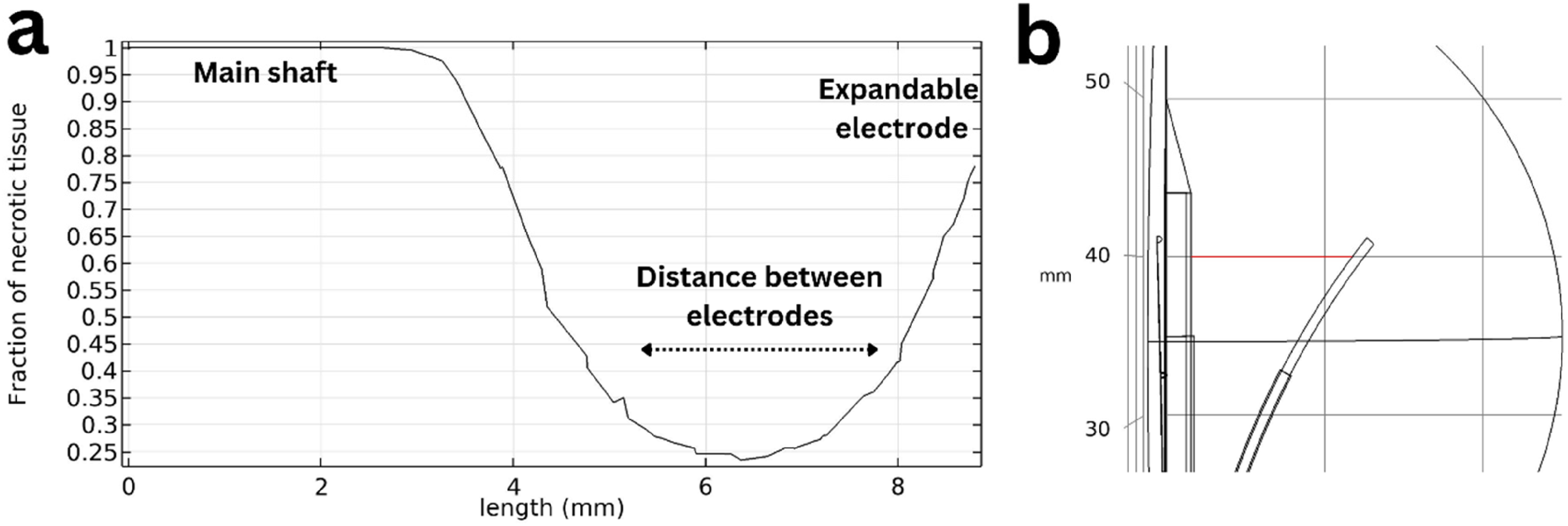
a. Fraction of coagulation necrosis plotted between the main shaft and expandable electrode; b. illustration of the cut line used for the plot for IRECT prototype (in red).
The image in Figure 8 displays a cross-sectional view of thermal tissue damage probability representing the modeled extension of coagulation necrosis, accompanied by a pathological image obtained from the previously published in vivo studies of swine liver 30 showing the white necrotic region after formalin staining. Only one figure was included for the swine liver for representability of the paper but more data taken from the previous published in-vivo study for all 10 swine's. All livers harvested from the swine's were pathologically documented and examined; the thermal damaged was observed. Additionally, the figure illustrates the temperature distribution in the liver and around the electrode.

a. Swine liver cross section showing white necrosis, b. necrotic tissue field taken at the middle of the main shaft, c. Temperature field of IRECT probe.
Discussion
In this study, thermal simulations of heat distribution during IRE were performed for different needle geometry and pulse protocols. The simulation of a classic IRE setup was compared to values from literature, and the simulation of the prototype was double checked with a previously made animal study. The results showed that the temperature decreased very fast with the distance, and the resulting necrosis due to Joule heating was hence located around the conductive part of the electrodes. The maximum average temperature during pulsation, located directly on the surface of the electrodes, was higher for the prototype (74 °C) than for classic IRE electrodes (57 °C) Additionally, the average current was greater for the prototype electrodes (0.0105 A) than for the classic IRE electrodes (0.002 A). However, the resulting thickness of the necrosis was in the same range for both configurations (1-3 mm). More interesting was the location, which differed completely: in our model, we simulate the liver without including the tumor. Necrosis was observed around the surface of the electrode for both configurations. According to literature.53,54 classic IRE electrodes cause necrosis in the healthy liver because the electrodes surround the tumor. In contrast, the IRECT prototype is designed to have the needle placed inside the tumor. For a tumor size of 1 to 3 mm, the thermal necrosis should be confined within the tumor. This can be seen in Figure 8, where the white necrosis is located in the center of the prototype. Moreover thermal ablation volume for the IRECT prototype was 2.43 cm3 while the classic IRE electrodes was 1.65 cm3.
Thermal effects can be strongly present during an IRE procedure and need therefore to be quantified and studied. Several studies recognized the importance of thermal effects during IRE and thermal models have been developed to investigate the temperature distribution during IRE, particularly focusing on the AngioDynamics NanoKnife® classic needle electrode geometry in combination with different pulse protocols and voltages. The maximal temperature range reported in these studies is typically between 40 °C and 50 °C measured at a distance of 5 mm away from the electrode, with direct thermal ablation confined to small regions around the electrodes. More needles lead to longer electroporation time and potentially higher temperature. Newer FDA-approved electroporation delivering device have built in temperature measurements and pause electroporation when measuring more than 85 °C 55 this value is measured directly at the electrode. The diameter of necrosis next to the active part of the needle is usually reported to be less than 3 mm in diameter depending on various factors, such as the specific tissue being ablated, pulse protocol and other experimental conditions.56–58 These literature values are compatible with the findings of the present article for the parallel electrode configuration where there was an increase of temperature up to 57 °C in the simulation of the classic IRE setup.
The effect of different electrode configurations on temperature has also been investigated in literature 59 showing that non-parallel electrode placement resulted in heterogeneous temperature distribution with the peak temperature focused in the area with the shortest inter-electrode distance. In addition, the geometry and number of the electrodes was reported to have an impact on the temperature. 60
Both findings are confirmed by the comparison between the classical two needle IRE configuration and the IRECT prototype simulations. For the IRECT probe with its five electrodes design, we observed a temperature rise up to 74 °C on the conductive part of the central electrode, and up to 49 °C at the middle of the satellite electrode. On the classic IRE setup, we observed a rise of temperature up to 57 °C, symmetric between the two electrodes. For both models, the same pulse protocol, input voltage, tissue properties and materials were used for the simulations; these settings resulted in a dissipated power during the pulse of 1.6 W for the IRECT case and 0.8 W for the classic IRE configuration. The IRECT used 0.01 J of energy, while the classic IRE configuration used 0.005 J. This difference in power is obtained with the same settings and pulse protocol and it is due to the differences in electrode's number and geometry. In particular, the active surface is approximately 3.5 times larger for the IRECT configuration (classic IRE has two electrodes with a total active surface of 48 mm² vs IRECT prototype that has five electrodes with 166 mm²), while the distance between electrodes is 3 to 1.25 times smaller (constant distance of 15 mm for the classic IRE configuration and varying distance for the IRECT probe ranging from 6 mm to 12 mm). The resulting temperature distribution depends on these geometrical characteristics, and it is difficult to predict beforehand without numerical simulations.
Like the classic IRE setup, the thermal damage near the IRECT prototype should be expected mainly in the proximity of the conductive part of electrodes. The temperature was locally larger in the IRECT case but drastically decreased as the distance from the electrodes increased. This was shown in this study where the difference in temperature between the central electrode and satellite electrode was around 20 °C.
The IRECT prototype was experimentally evaluated before in a study with 10 domestic pigs. 31 After applying the electric pulses, technical success was achieved in 9 out of 10 animals. At the end of the procedure, contrast-enhanced CT and MRI image was taken and animal livers were harvested for pathological evaluation. Thermal damage was observed, with coagulation necrosis corresponding to the area surrounding the central electrode in the direction of the four expandable electrodes.
The study showed that the coagulation necrosis observed in the measurements (up to 2 mm surrounding the central electrode) matched the region of thermal damage observed in the present simulation. Thermal damage was quantified in the simulations by looking at the 99% damage probability as coming from an Arrhenius model of tissue damage. It was also shown that the temperature rise was most pronounced in the proximity of the electrodes and in between them; the result was already found in literature. 34
This positive comparison to literature data and previously published experimental measurements, as discussed earlier in the text, demonstrates that computer simulations can reliably predict the thermal effects associated with IRE for different electrode configurations.
Reaching high temperatures during IRE is usually an undesirable effect that can be particularly dangerous near vital structures, 61 especially for the classic IRE needle setup: The needles are typically placed around the tumor and surrounded by healthy liver tissue, so they are more likely near a vessel, than a necrosis inside the tumor, where the heat of the IRECT prototype is generated. Furthermore, the maximal temperature is located at the main shaft, which means in the middle of the tumor, while it is lower at the satellite electrodes.
However, in the case of the IRECT probe, the necrosis at the central shaft may also be beneficial as it can contribute to the reduction of needle tract seeding 62 in comparison to the classic IRE setup, since the high temperature reached in the IRECT prototype may sanitize the central shaft and the expandable electrodes will be retracted inside the main shaft before extraction, which also contributes to minimizing the tract seeding effect.
Next steps will focus on increasing the realism of the numerical model described in the present paper. This is achieved by comparing more closely to the size and 3D shape of the IRE ablations observed in the swine experimental study 31 . Furthermore, realistic tumor geometries may be included in the computational setup as well as individual measured tissue properties instead of literature values 63 . In this study, we chose to quantify thermal damage using the well-established Arrhenius model. However, recent study suggests a temperature- dependent time delay at 43 °C, resulting in a heating protocol that is at least 24% shorter than that obtained using the traditional Arrhenius integral 64 .Incorporating this modified Arrhenius model into future work may lead to enhanced accuracy in the prediction of the thermal damage.
A modified Pennes Bioheat Equation that accounts for heterogeneous or anisotropic blood prefusion 65 should be considered. This modification includes varying levels of perfusion, ranging from high and moderate perfusion to low perfusion. Our study's use of the traditional Pennes Bioheat Equation is a limitation, as it may not fully capture the nuances of thermal energy distribution in tissues with heterogeneous perfusion. in this study, only zero perfusion was considered. This heterogeneity is important for irreversible electroporation and electrochemotherapy (IRECT), which depend on precise energy delivery. Moreover, the modeling of thermal damage in living tissues must consider the continuous regeneration of human tissues due to the arterial blood supply of oxygen. This regenerative process at the tumor-healthy tissue interface can reduce overall thermal damage accumulation within damage bound of Ω ≤ 1 66 . This would allow studying the effect of temperature distribution on the IRE ablation outcome for different tumor shapes, needle configuration, needle positioning and protocol settings. Also, the model could be used to investigate in more details the safety margins and optimal configurations that can prevent thermal damage of vital structures during IRE.
Conclusion
This study highlights the critical importance of understanding and quantifying thermal effects during Irreversible Electroporation (IRE) procedures, particularly in the context of different needle geometries. Our thermal simulations, validated against both literature values and experimental data from a previous animal study, demonstrate that the heat distribution is significantly influenced by the electrode configuration. The prototype IRECT probe, with its five-electrode design, generated higher peak temperatures than the classic two-needle setup. However, this high temperature was located inside the tumor and not in the healthy liver tissue. These findings underscore the necessity of detailed thermal analysis For more complex electrode geometries than classic IRE setups, highlighting the potential benefit of a treatment planning tool for physicians to ensure efficacy and safety.
Footnotes
Abbreviations
Acknowledgments
This work is a part of ElectroPros, a collaborative research project undertaken jointly by Uniklinik RWTH, Aachen and Philips Research, Eindhoven.
Author Contribution
Ali Jouni: Simualton preparing, computing, and manuscript writing
Marco Baragona: Simulation control
Federico Pedersoli: CT scans Reading and observing
Andreas Ritter: Supervision
Declaration of Conflicting Interests
The authors declared no potential conflicts of interest with respect to the research, authorship, and/or publication of this article.
Funding
The project has received funding from the European Union’s Horizon 2020 research and innovation program, under the Marie Sklodowska-Curie grant agreement number 813192.