
Abstract
Introduction
Even as various high-precision radiotherapy technologies are being developed, delivering the appropriate dose to malignant tumors with large areas and irregular surfaces remains challenging, and various treatment methods are still being tried. In particular, the chest wall, head and neck, and scalp, which are highly curved surfaces of the human body, require a high degree of skill to deliver a uniform dose to the surface where the lesion has spread while protecting internal organs. The high-energy photon beams used in radiation therapy exhibit a build-up phenomenon (skin-sparing effect) that produces a maximum dose at a certain depth when incident on a surface. Therefore, if the skin itself is the lesion, a tissue equivalent material (build-up bolus) with a similar density to the tissue can be used to deliver a uniform dose to the treatment. Selectively, short-range electron beams could be used to treat localized skin lesions such as basal cell cancer, squamous cell cancer, angiosarcoma, lymphoma, melanoma, mycosis, and breast cancer. Still, they may be limited in large and irregular areas.1,2
Especially when radiotherapy is required to treat the entire scalp, the shape of the skull makes it challenging to deliver the prescribed dose uniformly as the lesions are distributed along a severely curved surface. One of the radiotherapy methods for the whole scalp is to use a combination of electron and photon beams. Still, it is difficult to exclude the possibility that the dose is not evenly delivered at the junction of electron and photon beams. Mold-based high-dose rate (HDR) brachytherapy and volumetric-modulated arc therapy (VMAT) have recently been used for scalp radiation therapy. 3 Wojcicka JB et al 4 reported that in the case of 3-D conformal radiation therapy (3D-CRT), hot and cold spots could be observed in the brain tissue due to the migration of the treatment junctions. In addition, HDR brachytherapy has been reported to be superior to 3D-CRT in dose distribution, but it is more difficult to apply and less protective of the normal brain than VMAT. 5 On the other hand, it has been reported that the VMAT technique can achieve excellent planning target volume coverage and homogeneity index because the gantry rotates along the curvature of the scalp in a way that creates the most uniform dose distribution on the scalp while minimizing the dose delivered to the normal brain compared to 3D-CRT or HDR treatment.5,6 However, fabricating a bolus that covers the entire scalp is essential for stable surface dose by reducing the skin-sparing effect of high-energy photons. Therefore, for VMAT treatment with high-energy photons, a valid bolus should be fabricated, validated, and clinically applied to deliver appropriate doses to shallow lesions such as scalp cancer. 7 Generally, a dose-escalation bolus aims to accumulate a dose to the target by creating a thin layer in the range of 0.9-1.20 g/㎤ with a density similar to human tissue. Homemade bolus materials used in the clinic could include tissue equivalents such as wet cotton gauze, paraffin wax, and gels, while commercialized boluses (SuperFlab®) are usually made of elastic synthetic rubber with 5-mm or 10-mm thickness sheets.8,9 Commercially available boluses may not be suitable for targets with severe curvature like the scalp, as the shape of the scalp can prevent the bolus from fully contacting the skin, forming air gaps. Although 3D printing technology can be used to produce them, their use is limited due to material limitations, production time, and cost. Patient-specific boluses could be a reasonable solution for this kind of treatment, but fabricating low-cost, high-efficiency, patient-specific dose-enhancing materials poses significant challenges. 10
This study aimed to develop a thermoplastic patient-specific helmet bolus to deliver a uniform therapeutic dose to the target and minimize the dose to the normal brain during whole-scalp treatment with VMAT techniques.
Materials and Methods
Helmet Bolus Fabrication for CT Simulation
The bolus material was a commercial patient immobilization device double-shelled netting thermoplastic (MTAPUD 2.4 Head only, CIVCO, USA), and the holes in the netting were filled with melted paraffin to prevent voids from forming (Figure 1). The thermoplastic can easily conform to various shapes and surfaces, while the paraffin can quickly fill holes. For this experiment, a humanoid head phantom was used; it was positioned sitting upright to fabricate the scalp bolus. The scalp was sufficiently wrapped with a thermoplastic mask to create a patient-customized helmet bolus (Figure 2). After molding the thermoplastic to the head surfaces, it was removed from the phantom and filled with paraffin at 30 °C to fill the holes uniformly. To adjust the proper bolus thickness, the paraffin coating of the thermoplastic mask was repeated to achieve the desired thickness (around 5 mm) of the helmet bolus. 5 CT (LB, Canon, Japan) simulations were acquired using a large-diameter CT with a scan FOV of 70 cm, with scan conditions of 120 kVp, 20 mA, and a scan range of 170 mm. Image acquisition for treatment planning was performed using a humanoid head phantom with the bolus in place. To further validate the dimensions of the patient-customized bolus, 5 × 5 ㎠ pieces of bolus were prepared at the vertex (VX), occipital, right (RT), and left temporal (LT) regions of the head phantom. The effective density was measured using an electronic balance and electronic caliper.

Customized helmet bolus fabrication procedure. (A) Fabrication of double-shelled thermoplastic mask, (B) melting paraffin, (C) filling with melted paraffin, and (D) completed double-shelled mask bolus.
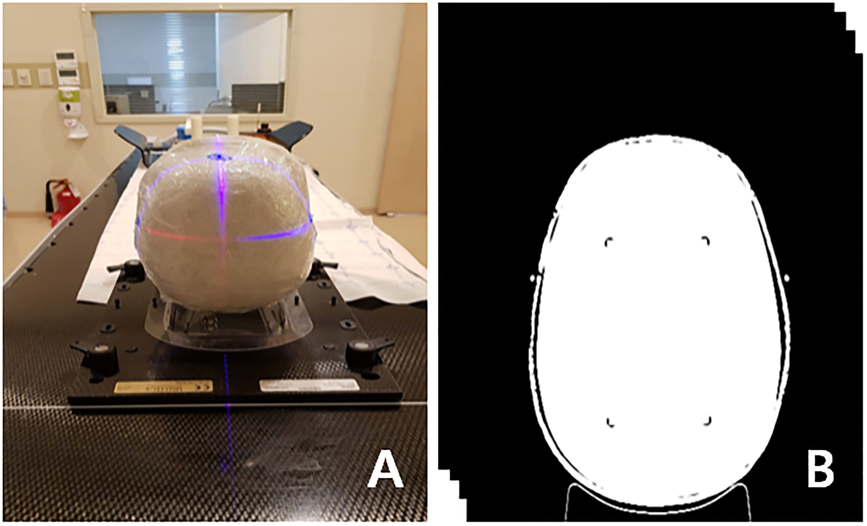
CT image acquisition for the simulated radiation treatment planning. (A) CT scanning setup and (B) CT image with thermoplastic mask bolus.
Dose Optimization for VMAT Planning
Two sets of CT images were registered in the radiation treatment planning system (Eclipse v13.6, Varian, USA) to assess the impact of the fabricated helmet bolus on dose distribution. The clinical target volume (CTV) for treatment planning was delineated as the scalp, excluding the skull. The organs at risk were set as the eyes, lens, brain, and skull (Figure 3). Figure 3 shows the prescribed dose distribution (pink) in axial, coronal, sagittal planes, and beam's eye view. The approximate priority setting was set as CTV (upper 950, lower 900, mean dose 950), skull (upper 550), brain (upper 650), eyes (upper 700), and lens (upper 800), and dose-volume optimization was applied to the treatment plan with and without bolus under the same conditions to perform inverse planning.11,12

Prescribed dose (66 Gy_pink) distributions on the (A) axial, (B) coronal, (C) sagittal planes and (D) beam's eye view (BEV).
For VMAT dose delivery, the arc beams for the irradiation were set to 2 full arc beams, collimator angles of 20 degrees, and 340 degrees, with a field margin of 5 mm across the entire arcs. The prescribed dose was 200 cGy in 1 fraction, 33 fractions. Analytical anisotropy algorithm was used to calculate the final dose distribution, and the dose calculation grid size was set to 2.5 mm. For quantitative dose distribution analysis, VMAT treatment plans with and without bolus were compared, and the dose distribution in the region of interest was analyzed to compare the dose difference between target and normal organs.
OSLD Measurements
The OSL chip in BeO material, which corresponds to a human effective density of 7, is a small circular chip with good user usability. It measures 4.7 × 4.7 × 0.5 ㎣ and weighs about 0.2 g, including the acrylonitrile butadiene styrene copolymer case, as shown in Table 1. Each item has a unique identification code in the form of a QR code. A corresponding reader can automatically scan these codes. The OSL detector was stimulated by approximately 480 ㎚ of blue light and converted into an electronic signal for reading the radiation dose. 13 Each dosimeter required registration, and as a calibration procedure, a local source was used to identify factors with standard irradiation. When calibrated individually according to their sensitivity, the dosimeters can accurately measure radiation exposure (Figure 4).
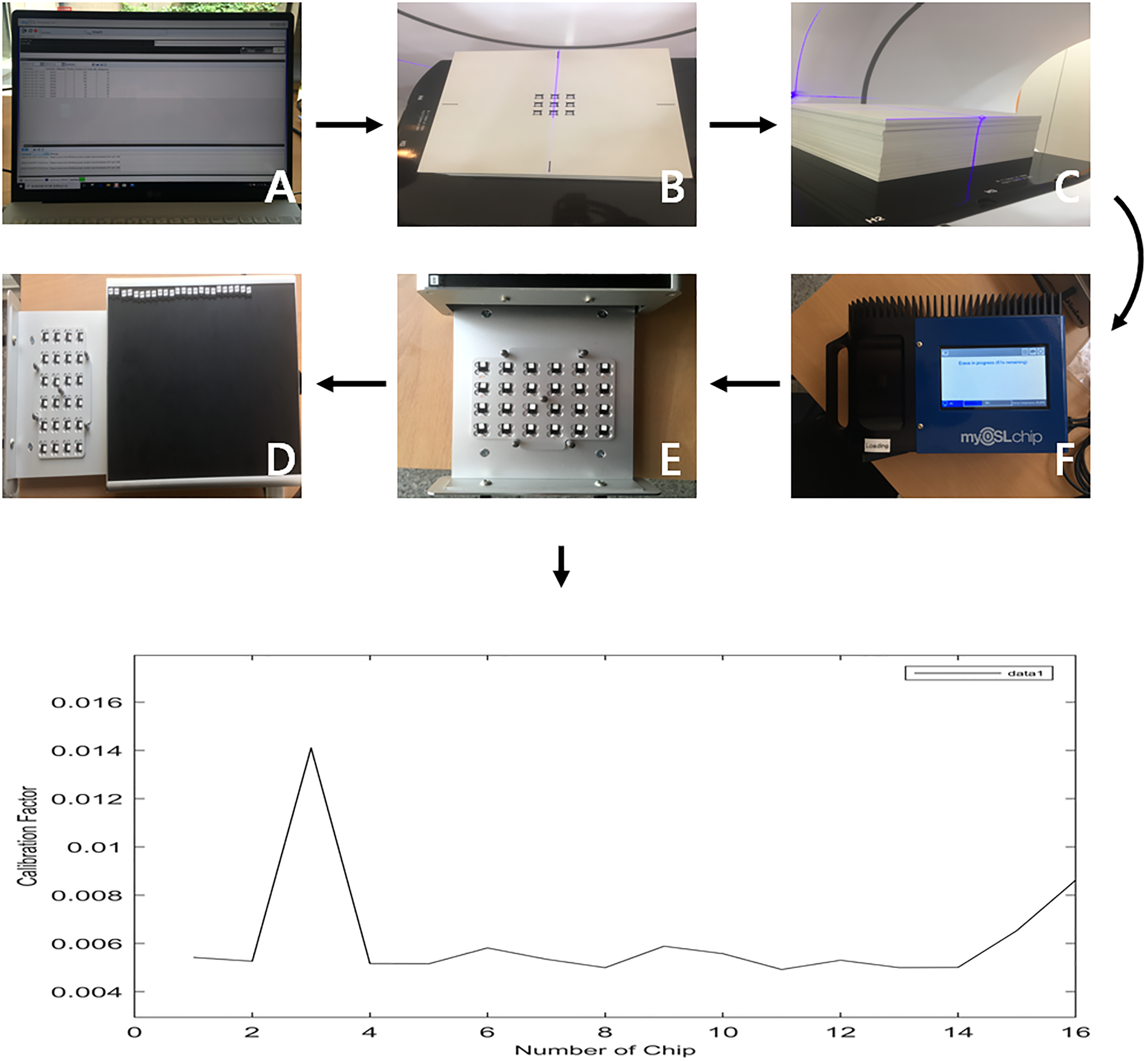
OSLD calibration procedure. Sequential procedures of OSLD calibration from (A) to (F), and the calibrated curve on the lower column.
Characteristics of OSLD System.

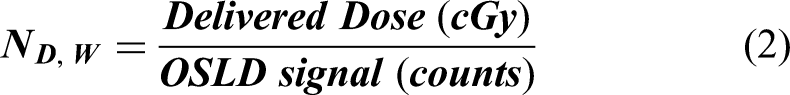
Four points on the entire scalp were designated to measure the dose. For quantitative analysis of the treatment dose, we attached OSLD chips at the VX, posterior occipital (PO), RT, and LT locations (Figure 5). The head phantom with the OSLDs attached was irradiated two times with/without the bolus. The OSLD chip was irradiated with 200 cGy at the same time. The basic formula for dose calculation is shown in Equation (1), which consists of the absorbed dose of water (D), dosimeter reading signal (M_Corr), correction factor (N_(D,W)), fading correction (K_F), linearity correction (K_L), beam quality correction (K_Q), and angle correction (K_θ). Then, based on the measured results, the applied dose was converted using the correction factors as shown in equation (2). As a result, the measured dose using OSLD was compared with the treatment plan results.14–17

Assigned points of OSLD. (A) vertex, (B) occipital, (C) right, and (D) left.
This study does not require IRB review because it does not involve human or animal subjects or their derivatives, and the radiation dose distribution was evaluated using a humanoid head phantom.
Results
Customized Bolus Density and Dose Distributions
The effective density of the patient-customized bolus made of thermoplastic and melted paraffin was investigated to determine if it approached the density of water. The VX, occipital, and bilateral temporal lobes of the temporal lobe were equally cut into 5 × 5 ㎠ sections, and the thicknesses were measured to determine the effective density. Table 2 shows that the measured densities for the VX, occipital, right, and left locations were 0.92 g/㎤, 0.81 g/㎤, 0.81 g/㎤, and 0.92 g/㎤ (average 0.87 g/㎤), respectively.
Effective Density at the Assigned Points.

VX, vertex; PO, posterior occipital; LT, left temporal.
Figure 6 shows the results of DVH analysis of CTV and normal tissue for each treatment plan to compare VMAT plans with and without bolus. In Figure 6, the average dose in CTV was 6553.8 cGy (99.3%) with bolus and 5874 cGy (89%) without bolus, a difference of more than 10% of the prescribed dose (6600 cGy) for the scalp target. For the normal brain, 3747.8 cGy (56.8%) with the bolus and 5484.6 cGy (83.1%) without the bolus. These results show a decrease in dose to the therapeutic target but an increase of more than 25% in the average dose to the normal brain, mostly occupied inside the therapeutic target. In addition, the mean doses with and without bolus were 4217.4 cGy (63.9%) and 3838.6 cGy (58.1%) in the skull, 864.6 cGy (13.1%) and 1775.4 cGy (26.9%) in the eyeball, and 620.4 cGy (9.4%) and 1122 cGy (17%) in the lens, with a dose increase of about 8%-13% except for the skull. Looking at the volume of CTV95%, it can be seen that the volume of 95% coverage with the bolus was 92.4% with the bolus, covering more than 90% of the treatment target, compared to 41.7% without the bolus, a difference of more than two orders of magnitude. Table 3 shows the difference between the minimum and maximum dose of each volume of interest for each treatment plan with and without boluses. With boluses, the CTV, brain, skull, eye, and lens were 64.0%-111.2%, 15.0%-106.7%, 11.2%-113.7%, 8.6%-20.7%, and 8.6%-10.9%, respectively; without boluses, 0%-116.4%, 31.2%-116.1%, 0.8%-120.0%, 11.4%-39.7%, and 10.4%-19.7%, showing a significant increase (7.0%-69.2%) in the dose difference between the maximum and minimum dose without bolus.

Dose-volume histogram of CTV and OAR with/without the thermoplastic helmet bolus from RTP results. CTV, clinical target volume; OAR, organs at risk.
OSLD Measurements versus Treatment Plan.

VX, vertex; PO, posterior occipital; RT, right temporal; LT, left temporal; W, with; W/O, without.
OSLD Measurements
For reproducibility and reliability of readings, measurements with OSLD were performed at least five times in the same setup, and two sets of readings with and without bolus are shown as the mean and standard deviation, respectively. The results were then expressed as a percentage of the prescribed dose in Table 3. When a bolus was used, the OSLD measured doses were 102.5 ± 1.2% for VX, 101.5 ± 1.9% for PO, 95.9 ± 1.9% for RT, and 81.8 ± 2.1% for LT. Additionally, the average doses in the treatment plan were 102%, 101%, 93.6%, and 80.7% for VX, PO, RT, and LT, respectively. The maximum doses were 103.4%, 103.2%, 97.7%, and 91.3% at the VX, PO, RT, and LT points. At the minimum dose of the treatment plan, doses of 100.9%, 96.5%, 87.1%, and 68.2% were seen at VX, PO, RT, and LT, respectively. In the absence of a bolus, the OSLD doses were 59.6 ± 2.4%, 112.6 ± 1.8%, 47.1 ± 1.6%, and 53.1 ± 2.3% at VX, PO, RT, and LT, respectively. Furthermore, the average doses at VX, PO, RT, and LT in the treatment plan were 77.6%, 57.3%, 38.7%, and 41.3%. The maximum doses were 87%, 85.2%, 53.8%, and 70.1% at the VX, PO, RT, and LT points, respectively. The minimum doses were 61.9%, 12.3%, 10.5%, and 1.1% for VX, PO, RT, and LT points, respectively.
Discussion
In this study, a customized helmet bolus for whole scalp radiotherapy was fabricated using a thermoplastic mask with melted paraffin. The results showed the effectiveness of the bolus and the utility value of the developed customized therapeutic bolus. The fabrication of the helmet-type bolus using a thermoplastic mask minimized the gap between the skin and the bolus, which could result in good reproducibility of the treatment setup in the clinic. The air gap between the scalp and the bolus was only 4.14 mm at most, which was superior to typical flat bolus reconstruction methods or commercial materials.4–7,18–21 However, modeling boluses, therapeutic implants, and customized accessories, especially for highly curved areas, was not straightforward, which is one of the reasons for the recent use of 3D printers in radiotherapy.
Zou W et al 22 reported that 3D printers can be useful for making compensators for photon beams and boluses for electron beam therapy; however, depending on the material being printed, they have been shown to cause discomfort and be time-consuming. Therefore, they have many limitations that need improvement before they can be applied to workflows for patient treatment.10,23–25
The study confirmed the feasibility of the proposed bolus via OSLD measurements and planning results. Previous studies have shown that the dose reduction ranged from 5% to 12%, depending on the field size, beam incidence angle, and air gap. However, in this study, the CTV received an average of 99.3% of the prescribed dose. We found that the customized helmet bolus was more effective than previous studies using conventional flat bolus and 3D-printed bolus.26–28 Notably, there was a deviation in dose distribution, indicating a 64%-111.2% difference. The thickness of the scalp blouse may vary depending on the location, which could be a cause for concern as it covers the scalp with a thermoplastic mask. Although the thickness on both sides in Table 2 was slightly lower than at other sites, which could lead to a dose variation, the measurement results seemed insignificant. Furthermore, even though there were concerns about the possibility of an overdose of the eye and lens, the doses measured in this study were found to be acceptable. Specifically, the eye and lens doses were 13.1% and 9.4% of the prescribed doses, respectively. 18
This study showed that in VMAT treatment of the scalp, significant errors (∼116.4%) in the inverse planning and dose calculation of the RTP if the appropriate bolus is not used. Moreover, the brain could receive approximately 46.3% more doses without the bolus. Similarly, the eye and lens may receive 105.3% and 80.9% more doses, respectively. The OSLD and prescribed dose also showed a 5%-20% difference in RT and LT results. This can be speculated to be the result of electronic disequilibrium, which can occur in extreme situations where the entire surface is in the treatment range due to the nature of the high energy. Three possible factors could explain the difference observed. Firstly, the difference in bolus thickness, as mentioned earlier. Secondly, some voids were created by the ears’ anatomy, which were partially protruding. Thirdly, a previous study 29 concluded that dose reduction can occur when close to bone, such as in the temporal lobe of the skull, which may support this dose difference. Additionally, inconsistent treatment plans and OSLD values were observed when the bolus was not used. These results demonstrate the necessity of using a bolus in scalp treatments and show that this method effectively fabricates the customized bolus. However, some scattered beams through the portal may result in a higher than prescribed dose for the scalp. There may be errors in the OSLD measurements contributing to dose differences. OSLDs require caution due to their varying responsiveness based on energy characteristics. It was found that the presence or absence of OSLD at the treatment site had an impact on the results of previous studies. Therefore, it is important for users to exercise caution while using OSLDs. It is necessary to validate and incorporate high-energy and low-energy measurements in the calibration process.30–36
Conclusion
In this study, we propose a method for creating patient-specific boluses that are highly reproducible, accessible, and easy to fabricate for radiotherapy of the entire scalp. The boluses are designed to effectively protect normal tissues while delivering sufficient surface doses. Our goal with this method is to demonstrate the impact of the in-house fabricated helmet bolus on dose distributions and present the methodology through simulations using a head phantom. Although the method has not yet been tested on actual patients, we strongly believe that our research results show that it is a highly effective approach that can be integrated into clinical workflows.
Footnotes
Acknowledgments
None
Declaration of Conflicting Interests
The authors declared no potential conflicts of interest with respect to the research, authorship, and/or publication of this article.
Ethics Statement
The authors declare that they have followed all appropriate research and ethical guidelines for the conduct of this research.
Funding
The authors received no financial support for the research, authorship, and/or publication of this article.