
Abstract
Introduction
Stereotactic body radiation therapy (SBRT) has become one of the most common radiotherapy regimens, particularly for early stage primary and oligometastatic cancers.1–4 It can deliver high doses to tumors in conjunction with a hypofractionated regimen, resulting in a high biologically effective dose. Several studies have demonstrated the potential benefits of SBRT in terms of local control and subsequent overall survival.5–8 However, the adjacent organs-at-risks (OARs) surrounding a tumor are generally radiosensitive. Thus, to spare the adjacent OARs, a steep dose fall-off outside the target volumes is essential. Rapid dose gradients are generated by the simultaneous and complex modulation of multileaf collimator (MLC) positions, gantry rotation speed, and dose rates. Even a small amount of uncertainty regarding such factors can have a critical impact on treatment. Therefore, SBRT requires a high level of confidence and special attention to the accuracy of the entire treatment procedure. Thus, the pretreatment quality assurance (QA) of SBRT is important for safe and effective SBRT.
A typical QA method exploits a water-equivalent phantom to measure the point dose and two-dimensional (2D) dose distribution. This phantom-based QA is intuitive for clinical use and has the advantage of measuring the actual dose delivered to the phantom. However, this method has several inherent limitations. One of the significant disadvantages is that it may not reflect the tissue heterogeneity of the patient as the treatment plan is delivered to a homogeneous phantom. In addition, physical factors such as the setup position of the phantom, chamber, and film adversely affect the measurement accuracy. Thus, careful management of many physical factors is desirable. Furthermore, it is difficult to simultaneously measure the point dose at several locations. Some phantoms offer multiple measurement locations. However, it is not clinically practical to equip several chambers or to perform multiple measurements with one chamber while changing the position. Moreover, it is difficult to verify the overall three-dimensional (3D) dose distribution, because only 2D planar dose distribution measurements are inherently available.
To overcome these limitations, various pretreatment QA methods have been proposed using innovative devices and algorithms.9–19 Among these, dose-volume histogram (DVH)-based patient-specific QA has emerged in recent years. The DVH-based method enables the calculation of dose distributions in the patient domain, where tissue inhomogeneity is considered. In general software, because the DVH-based method provides more relevant comparisons of dose distributions, various commercial products such as Mobius3D/FX (Varian Medical Systems, Inc., CA, USA), RadCalc (LAP, Lüneburg, Germany), PerFRACTION (Sun Nuclear Corp, FL, USA), and Dosimetry Check (Math Resolution, MD, USA) have been released and clinically implemented.20–28
Mobius3D/FX, a DVH-based patient-specific QA tool, has been employed at multiple institutions for clinical use. Mobius3D enables independent verification of the treatment planning system (TPS) using its convolution-superposition dose calculation algorithm. MobiusFX uses the same dose calculation algorithm as Mobius3D. However, it uses treatment log files to calculate the 3D dose distribution under the actual treatment state of the linear accelerator (LINAC). Various studies have evaluated the dose calculation accuracy and validity of Mobius3D/FX in clinical use. Early investigations mainly showed commissioning results. However, in recent years, comparative studies for an overall range of clinically relevant plans, including intensity-modulated radiation therapy (IMRT) and volumetric-modulated arc therapy (VMAT), have been performed.20–22,29,30 Moreover, detailed characteristics of Mobius3D/FX, such as the dosimetric leaf gap (DLG) correction factor, have been explored for optimal performance.20–22,30,31 In summary, in-depth evaluations of dosimetric accuracy of Mobius3D/FX for IMRT and VMAT plans have been actively performed. Yet, dosimetric accuracy for SBRT plans that mostly use flattening-filter-free (FFF) x-ray beams with small fields has not been intensively studied.
The purpose of this study is to investigate the dose calculation accuracy of Mobius3D for small-field FFF photon beams, which are mainly employed for SBRT cases. Although the dose calculation of MobiusFX was not included in the scope of this study, evaluating the dose calculation accuracy of Mobius3D will be an essential step in assessing the feasibility of MobiusFX for pretreatment verification. As several studies already reported the inaccuracy of dose calculation and MLC modeling in Mobius3D,20,21,30,32 clinical applications on SBRT may be adversely influenced by these current limitations. In this work the results of diverse studies for a comprehensive understanding of these limitations are discussed. Our study aims to validate whether the dose calculation accuracy of Mobius3D is adequate enough to be employed as a patient-specific pretreatment verification for SBRT. We performed the experimental study with an artificial plan to evaluate the accuracy of small-field modeling, including both on-axis and off-axis. Moreover, the dose calculation accuracy of Mobius3D was evaluated for SBRT plans with multiple targets, where obtaining accurate results is expected to be challenging. A set of measurement-based dose verification equipment, including the Octavius 1000 stereotactic radiosurgery (SRS) (PTW, Freiburg, Germany), ionization chambers, and EBT3 radiochromic films, was used to compare and validate the dose accuracy of Mobius3D for small-field FFF photon beams.
Methods
Mobius3D Commissioning
Mobius3D version 4.0.1 was commissioned for an Elekta VersaHD LINAC machine equipped with an Agility MLC for unflattened 6 MV and 10 MV x-ray beams. The commissioning procedures were performed in five steps: (1) verification of the machine output calibration factor, (2) verification of the beam modeling, (3) verification of the computed tomography (CT)-to-density table, (4) open field test, and (5) verification of the Mobius3D dose calculations on patient plans. The detailed methods are described in our previous studies20,21 and executed in the same manner accordingly. In this study, the percentage depth dose (PDD) and off-axis ratio (OAR) values were unchanged, so that the Varian-provided reference values were utilized. Only the output factors (OFs) were replaced with the measured values used in the TPS for clinical use. For DLG optimization, 10 patient plans for each energy level were employed. These plans were selected for DLG optimization, as they have relatively large MLC openings compared to other patient plans, as reported in our previous studies. To obtain unbiased DLG correction factor, we excluded small-field plans for DLG optimization, which is also the vendor's recommendation. The characteristics of the patient plans selected for DLG optimization are summarized in Supplemental Tables S-A-1 and S-A-2 for unflattened 6 MV and unflattened 10 MV, respectively (see Supplemental material A). RayStation version 5.0.3.17 (RaySearch Laboratories, Stockholm, Sweden) was utilized to create patient plans. The collapsed cone convolution algorithm was used for the photon beam dose calculation in this investigation. The RayStation commissioning was thoroughly performed by professional medical physicists. In summary, the Mobius3D beam models were fine-tuned to best match the measured beam data according to vendor-suggested commissioning steps.
Experimental Study with Artificial Plans for Small-Field Modeling Accuracy in Both On-Axis and off-Axis
An experimental study with an artificial plan is performed herein to investigate the characteristics of Mobius3D for small-field modeling. It includes both on-axis and off-axis and their accuracy, according to the DLG correction factor. In this work, the accuracy of the dose calculation of Mobius3D was evaluated for each of the three x-ray energies: unflattened 6 MV (6 MV-FFF), unflattened 10 MV (10 MV-FFF), and flattened 6 MV for comparison. Artificial plans were created with four different field sizes and 13 different locations. Thus, 52 scenarios in total were included in the plan for each x-ray energy, as displayed in Figure 1. Each field was designed to deliver 100 monitor unit through square fields ranging from 1 to 4 cm. For a detailed analysis of the accuracy of beam modeling in the off-axis direction, 13 different locations were subdivided into four groups according to the radial distance from the isocenter.

Schematic diagram of artificial plans for small-field modeling accuracy of both on-axis and off-axis.
For the measurement, an Octavius 1000 SRS, a liquid-filled 2D ionization chamber array, was employed. Its 2D array of detectors consists of 977 liquid-filled ion chambers arranged over an area of

Description of the experimental study with Octavius 1000 SRS: (a) image of the phantom and (b) the schematic diagram of the experimental setup for the measurement. (c) Displays the screenshot of a dose distribution calculated on the CT scan of the phantom setup using RayStation. Abbreviations: CT, computed tomography; SRS, stereotactic radiosurgery; SSD, source-to-surface distance.
The dose distributions for each field were calculated from the CT scan of the phantom setup, including the slab phantom and Octavius 1000 SRS (Figure 2c), using RayStation and Mobius3D, respectively. RayStation utilizes a collapsed cone convolution algorithm for dose calculations, whereas Mobius3D employs a simplified version. The mean calculated dose in a sphere volume close to the chamber cavity volume was compared to the measured dose. One of the research goals included evaluating the effect of the DLG correction factors and determining the optimum. Hence, Mobius3D doses were recalculated by changing the DLG correction factors from −1 to 1 in increments of 0.5.
Experimental Study with Multitarget Patient Plans
To further evaluate the dose calculation accuracy of Mobius3D for SBRT in actual clinical practice, a study was conducted using patient cases with multiple targets. Among various plan parameters related to the field size, the individual planning target volume (PTV) diameter was set as the target dimension in this study. Moreover, to specify the criteria for detailed analysis of small-field cases, they were subdivided into three groups (5-10, 10-20, and 20-30 mm). A thorough search was performed to find plans that met the target dimension criteria. All plans created between January 2019 and December 2020 were searched for an Elekta VersaHD linear accelerator.
As a result of the search, only 10 plans with multiple targets were found for both the 6 and 10 MV-FFF (Table 1). Among these clinically available plans, three plans were selected for the study: one plan with 6 MV-FFF for a PTV diameter of 20-30 mm and two plans with 10 MV-FFF for PTV diameters of 5-10 and 10-20 mm. The characteristics of the selected patients are summarized in Table 2. No multitarget plans were found for PTV diameters of 5-10 and 10-20 mm with 6 MV-FFF and for PTV diameter of 20-30 mm with 10 MV-FFF. Therefore, 6 MV-FFF plans with an equivalent plan quality were created for patients with targets of 5-10 and 10-20 mm PTV diameters. A counterpart (10 MV-FFF plan) was created for the patient with targets of 20-30 mm. The average MLC opening width was calculated for the selected plans. Details of the average MLC opening calculation are described in Kim et al. 21 The calculated average MLC opening widths for each plan are listed in Table 2.
The Number of Clinically Available Plans Having Multiple Targets with Specified Target Dimensions, Created for an Elekta VersaHD Linear Accelerator.
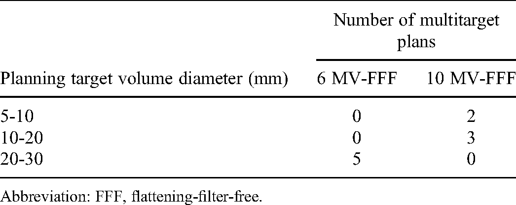
Abbreviation: FFF, flattening-filter-free.
Characteristics of the Selected Multitarget Patient Plans.

*A counterpart plan was created by performing plan optimization with the same dose objectives and constraints.
Abbreviations: FFF, flattening-filter-free; Fx, number of fractions; MLC, multileaf collimator; MU, monitor unit.
The radiation doses of the selected plans were measured using a Gafchromic EBT3 film. The selected plans were delivered to an ArcCHECK phantom (SNC, Melbourne, FL, USA) with multiplug inserts so that the film was located at the central coronal plane of the phantom. Film calibration was performed at the time of measuring the planned doses to accurately convert optical density values to radiation dose values for radiation doses in the range of 0-18 Gy.
For the selected plans, ArcCHECK phantom plans were created to calculated doses delivered to the phantom, with the use of RayStation. The phantom plans were imported into Mobius3D. Radiation doses were calculated using various DLG correction factors. The phantom plans were calculated with several DLG correction factors around the optimal DLG correction factor. They will be presented in the Results section: −1.5, −1.0, and −0.5 for 6 MV-FFF and 0.5, 1.0, and 1.5 for 10 MV-FFF.
To compare the measured and calculated doses, an in-house MATLAB script was created, facilitating fast and consistent analysis across patient plans with two different x-ray energies. Irradiated films was scanned with a spatial resolution of 71 dots per inch corresponding to a pixel size about 0.35 × 0.35 mm2. A median filter of 5 × 5 pixels was applied to the scanned film images to eliminate the effect of noises. Film-measured and computed doses were interpolated with voxel dimensions of 1 mm in all directions. Gamma analysis was performed with a criterion of 3%/2 mm and a 10% dose threshold. The dose-difference tolerance was set to 3% of the maximum dose value for the entire dose range (absolute global). Prior to gamma analysis, rigid image registration was performed to align the film dose with the computed dose, eliminating setup uncertainties. The detailed procedures of the registration are described in Supplemental material B. Average dose difference in the region corresponding to more than 50% of the maximum dose was also calculated.
This study was approved by the Institutional Review Board (IRB, approval number: 4-2020-0597) of the Severance Hospital. All data were fully anonymized before they were accessed by the investigators. Given the retrospective nature of the study, the requirement for written informed consent was waived by the IRB. The reporting of this study conformed to STROBE guidelines. 33
Results
Mobius3D Commissioning
The beam data values of the 6 and 10 MV-FFF x-ray beams for the linear accelerator are summarized in Supplemental Tables S-C-1 to S-C-3. They were measured using a PTW BeamScan water phantom. The measured PDD, OAR, and OF values are summarized in Supplemental Tables S-C-1 to S-C-3, respectively. As mentioned in the Methods section, only the output factors in Mobius3D were replaced with the measured values that were used in the RayStation instead of employing Varian-provided reference values.
The optimal DLG correction factors obtained for 6 and 10 MV-FFF were −1.4 and 1.4, respectively. The detailed results of the DLG optimization for each energy level are presented in Figure 3.

DLG optimization results performed for (a) 6 MV-FFF and (b) 10 MV-FFF. Abbreviations: DLG, dosimetric leaf gap; FFF, flattening-filter-free; Fx, number of fractions; M3D, Mobius3D.
Experimental Study with Artificial Plans for Small-Field Modeling Accuracy in Both On-Axis and off-Axis
The differences between the calculated and measured doses of each x-ray energy according to the field size and off-axis distance from the isocenter are shown in Figure 4a to e (6 MV-FFF) and Figure 5a to e (10 MV-FFF). From the dose measured by Octavius 1000 SRS, the doses calculated by RayStation and Mobius3D were compared. In Mobius3D, the doses recalculated by changing the DLG correction factors were used for comparative analysis.

(a) and (e) Dose difference of artificial plan test for 6 MV-FFF, which compares the M3D-calculated with various DLG correction factors and Ray-calculated doses to the measurements by Octavius 1000 SRS. (f) Average dose difference of artificial plan test for 6 MV-FFF according to the DLG correction factors. Abbreviations: DLG, dosimetric leaf gap; FFF, flattening-filter-free; FS, Field size; M3D, Mobius3D; Ray, RayStation; SRS, stereotactic radiosurgery.
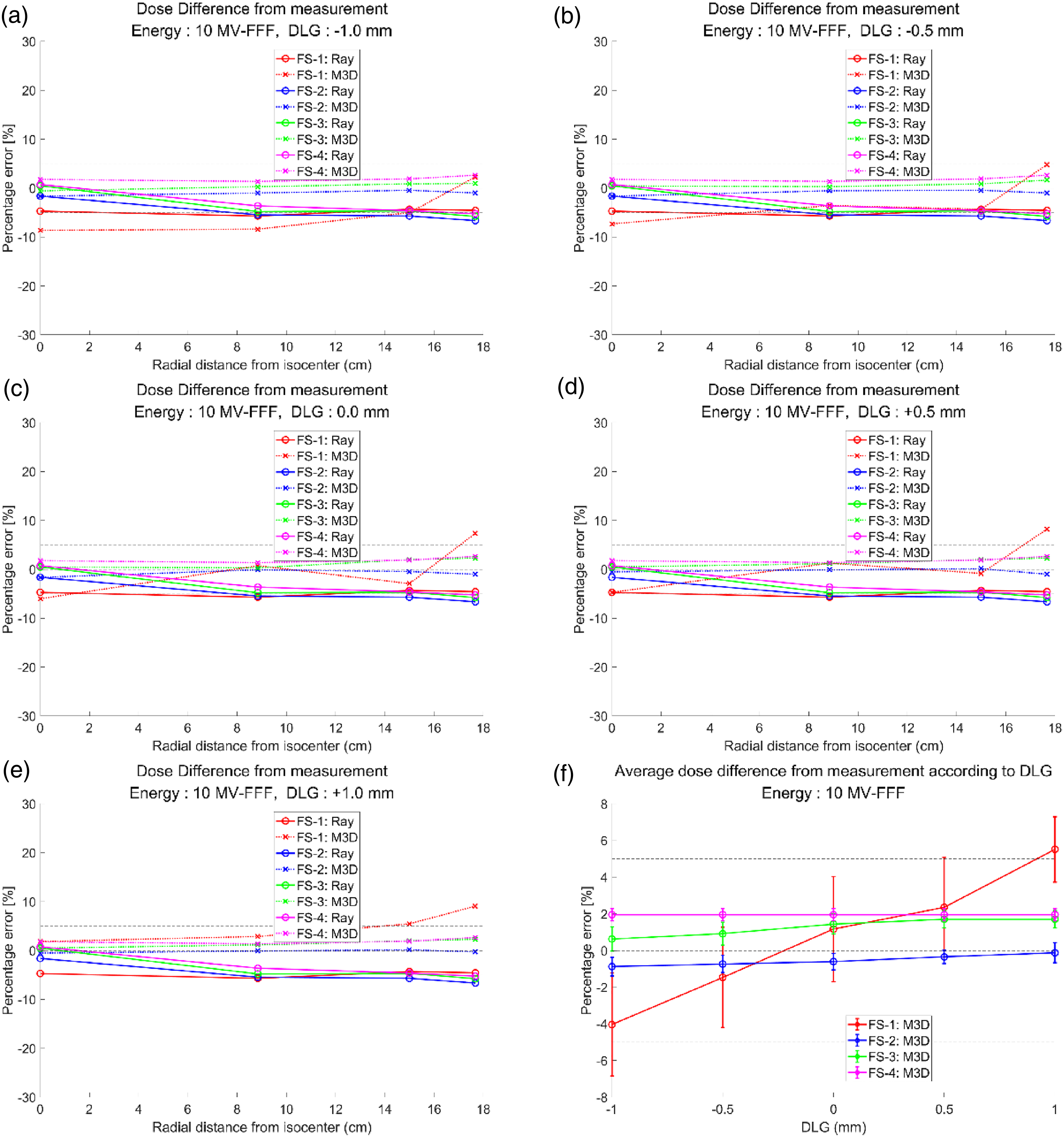
(a) and (e) Dose difference of artificial plan test for 10 MV-FFF, which compares the M3D-calculated with various DLG correction factors and Ray-calculated doses to the measurements by Octavius 1000 SRS. (f) Average dose difference of artificial plan test for 10 MV-FFF according to the DLG correction factors. Abbreviations: DLG, dosimetric leaf gap; FFF, flattening-filter-free; FS, Field size; M3D, Mobius3D; Ray, RayStation; SRS, stereotactic radiosurgery.
The dose calculated by RayStation showed no significant difference from the measured value, regardless of the field size and off-axis distance, in both 6 and 10 MV-FFF. In contrast, in Mobius3D, the calculated doses showed a relatively large difference from the measured values overall, compared to those of RayStation. Among them, an absolute difference of up to approximately 10% was observed when the field size was 1 cm. The maximum absolute error was 9.96% for the 6 MV-FFF and 9.07% for the 10 MV-FFF.
Similarly, in the flattened 6 MV included for comparison (see Supplemental Figure S-D-1), the dose difference was negligible in all cases, except for the 1 cm field size. However, it showed a larger dose difference than the unflattened 6 MV and unflattened 10 MV.
For an in-depth analysis of the dose calculated by Mobius3D according to the change in the DLG correction factor, the average doses of 13 different locations were calculated, as shown in Figures 4 and 5, and Supplemental Figure S-D-1 (f). As the DLG correction factor varied, a change in dose difference was observed in all field sizes. It was considerable only in the 1 cm field size. It was negligible in the remaining cases.
Experimental Study with Multitarget Patient Plans
The results of comparing the Mobius3D-calculated and RayStation-calculated doses with the measured doses are summarized in Tables 3 and 4, Figures 6 to 9, and Supplemental material E. It is noted that the Mobius3D dose calculations were performed with a range of DLG correction factors around the optimal values obtained by a separate DLG optimization. Since the optimal DLG correction factors derived in this work were already out of the clinically relevant range (from −1 to 1) recommended by the vendor. Thus, they were varied only in the direction in which the absolute value decreased.

Two-dimensional distributions of the film-measured, computed doses (RayStation and Mobius3D) and gamma indices for patient 1 (6 MV-FFF). Abbreviations: DLG, dosimetric leaf gap; GPR, gamma passing rates.

Comparisons of the (a) lateral and (b) longitudinal profiles of the measured and computed doses along the orthogonal lines plotted in Figure 6 for patient 1 (6 MV-FFF), where right-hand side figures are zoomed-in images of the left-hand side figures. Abbreviation: DLG, dosimetric leaf gap.

Two-dimensional distributions of the film-measured, computed doses (RayStation and Mobius3D) and gamma indices for patient 1 (10 MV-FFF). Abbreviations: DLG, dosimetric leaf gap; GPR, gamma passing rates.
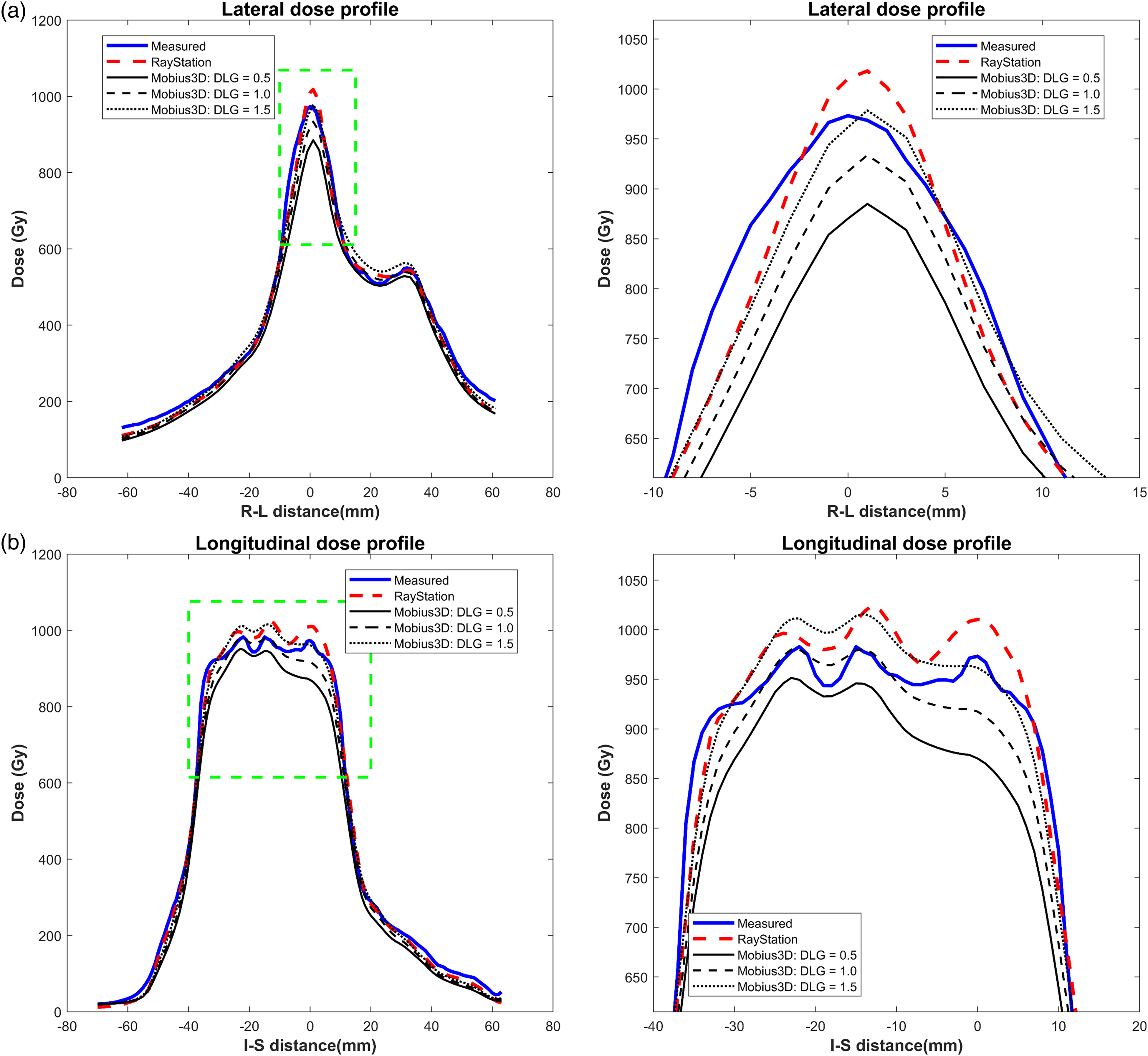
Comparisons of (a) lateral and (b) longitudinal profiles of the measured and computed doses along the orthogonal lines plotted in Figure 8 for patient 1 (10 MV-FFF), where right-hand side figures are zoomed-in images of the left hand side figures. Abbreviations: DLG, dosimetric leaf gap; FFF, flattening-filter-free.
Summary of the GPR and ADD for the 6 MV-FFF Plans.
Abbreviations: ADD, average dose differences; DLG, dosimetric leaf gap; FFF, flattening-filter-free; GPR, gamma passing rates.
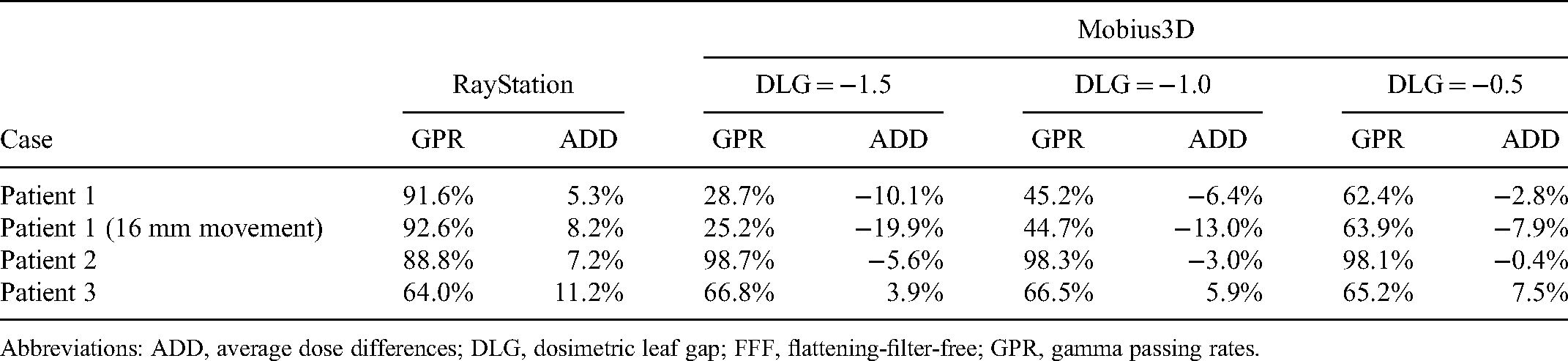
Summary of the GPR and ADD for the 10 MV-FFF Plans.

Abbreviations: ADD, average dose differences; DLG, dosimetric leaf gap; FFF, flattening-filter-free; GPR, gamma passing rates.
Overall, the Mobius3D-calculated doses agreed better with the measured doses for the 10 MV-FFF than for the 6 MV-FFF. For the 6 MV-FFF, the mean gamma passing rates (GPR) with 3%/2 mm gamma criterion were 54.8%, 63.7%, and 72.4% for Mobius3D with DLG correction factors of −1.5, −1.0, and −0.5, respectively. The mean GPR was 84.2% for RayStation. The mean of average dose differences were −7.9%, −4.1%, and −0.9% with DLG correction factors of −1.5, −1.0, and −0.5, respectively. The mean of average dose difference was 8.0% for RayStation. For 10 MV-FFF, the mean GPRs were 73.6%, 84.2%, and 90.0% for Mobius3D with DLG correction factors of 0.5, 1.0, and 1.5, respectively. The mean GPR was 93.9% for RayStation. The mean of average dose differences were −6.5%, −2.9%, and 0.7% with DLG correction factors of 0.5, 1.0, and 1.5, respectively. The mean of average dose difference was 1.2% for RayStation.
While the degree of agreement between the measured and calculated doses was different for the two x-ray energies, a similar trend was observed. For patient 1 with the smallest target, the Mobius3D-calculated dose was lower than the measured dose. The dose of Mobius3D was underestimated compared with the measured values. Thus, low GPRs were observed regardless of the DLG correction factor (see Figures 6 to 9). In this case, to further validate other positions that cannot be covered by original setup, remeasurement was performed by moving the phantom 16 mm vertically upwards. The overall results were similar. The dose of Mobius3D was still underestimated, as shown in Supplemental Figures S-E-1 to S-E-4. For patient 2 with medium-sized targets, the Mobius3D-calculated doses reasonably agreed with the film-measured doses. In contrast, for patient 3 with larger target volumes compared to other cases, the Mobius3D-calculated doses were generally higher than the measured doses. In this case, because of the dose overestimation of Mobius3D, the agreement between the dose distribution and measured values was low. Thus, it showed low GPRs. The RayStation-calculated doses are also presented to facilitate a further comparison of the doses computed by the TPS in clinical use.
Discussion
This study evaluates the dose calculation accuracy of Mobius3D for small-field FFF photon beams that are mainly used for SBRT. The commissioning results of Mobius3D include comparisons of the measured beam data (PDD, OAR, and OF values) with the vendor-provided reference values. Furthermore, DLG optimizations for each energy were conducted according to the Mobius3D guidelines. After Mobius3D commissioning for 6 and 10 MV-FFF, two types of experimental studies were performed to investigate the accuracy of small-field modeling in Mobius3D. The study with artificial plans was designed to confirm the dose calculation accuracy according to the off-axis distance and field size. It aimed at a specific analysis of the dose calculation accuracy according to the physical factors. Another study with patient plans was conducted to demonstrate the overall influence of small-field modeling in Mobius3D on actual clinical practices. Both studies evaluated the dose calculation accuracy through comparisons with the measured data. The overall results showed that the Mobius3D dose calculation for the FFF x-ray beams is inaccurate for clinical use, especially in extremely small fields, such as <1 cm. In summary, it is currently difficult to employ Mobius3D as the main pretreatment QA tool for small-field SBRT. Therefore, several considerations are necessary to facilitate its use in clinical practice.
There was a slight difference between the measured PDD, OAR, and OF data of the Elekta VersaHD system and vendor-provided reference values. The dose differences in the entire PDD, OAR within 5 cm, and OF over 2 cm field size were <1%. This indicated that the relevant beam model was relatively accurate. However, dose differences of approximately 2% to 3% were observed in OAR farther than 5 cm and OF at 1 cm field size. The results showed that the dose calculation accuracy might be degraded under certain circumstances with a small field size or a large off-axis distance. Thus, beam modeling needs to be improved. However, beam modeling in Mobius3D can be adjusted through a fine-tuning process in which the user inputs the measured data. In this study, only the OFs were replaced with the measured values, whereas the PDD and OAR values did not change. The accuracy of the Mobius3D dose calculation might be improved by applying the beam model adjustment for PDD and OAR. However, the effect of beam model adjustment for PDD and OAR would not be significant. The experimental results with the artificial plan showed a change in the dose difference according to the off-axis distance. However, the change was not very considerable. However, although the measured OFs were employed, the change in the dose difference according to the field size was significant. Thus, there is an intrinsic limitation of unflattened photon beam modeling in Mobius3D that cannot be overcome by user adjustment. This obstacle is difficult to overcome until Mobius3D itself is supported and improved.
The DLG correction factor is another physical factor that considerably influences dose calculation accuracy in Mobius3D. As established in previous studies, the DLG correction factors of Mobius3D do not fully consider the physical properties of MLC. Thus, the MLC model and relevant DLG correction factor should also be improved to achieve accurate dose calculations across a full spectrum of clinical plans. 34 The DLG correction factors in Mobius3D adjust only the MLC opening width in the MLC direction, thereby controlling the overall dose level. However, there was no effect on the dose profiles in the jaw direction. This type of modeling, which simply shifts the position of the MLC, is somewhat inaccurate. Thus, careful attention is required to determine the optimal DLG correction factor. The optimal DLG correction factors determined in this study by the vendor-recommended method were out of the clinically relevant range. It indicated that MLC modeling is imperfect. The adverse effects of these MLC modeling inaccuracies were observed in the results of artificial plan test. From the figures showing comparisons between RayStation and Mobius3D, plotted in Supplemental material F, they indicated that output and penumbra shape between RayStation and Mobius3D are not accurately matched. They show that MLC modeling in Mobius3D is imperfect in small field, and it was also observed that the influence of MLC modeling inaccuracies were much more severe with smaller field size. With the existence of the inaccuracy, it may be infeasible to determine a DLG correction factor that can be used for the entire range of clinical plans, particularly with small fields.
The results of the flattened 6 MV beam were investigated in this study for comparison with unflattened photon beams. These results showed a tremendous dose difference (up to −30%) in the 1 cm field size. This is because the OF of 1 cm field size in the flattened 6 MV beam is not intrinsically defined in Mobius3D, unlike unflattened photon beams. The OF of the smallest field size defined in 6 MV was 2 cm. The OF of the smaller field size was calculated through the extrapolation process. Therefore, the uncertainty in the dose calculation may increase, leading to a severe dose deviation.
In summary, Mobius3D dose calculation uncertainties for small-field FFF photon beams were reported. Based on the results presented above, it can be concluded that the Mobius3D dose calculation accuracy for unflattened x-ray beams needs to be improved for use in SBRT pretreatment QA in clinical practice. Future studies can further evaluate the Mobius3D dose calculation accuracy using different types of artificial plans or more patient plans. Moreover, comparing the dose calculation accuracy with other commercial products of DVH-based QA methods would be another future study. We also envision performing a comparative study not only on Elekta's LINAC, but also on other vendors’ LINAC systems, such as Varian.
Conclusions
This study demonstrated that Mobius3D has dose calculation uncertainties for small-field FFF photon beams. These uncertainties arise mainly from the inaccuracy of beam modeling and MLC modeling of Mobius3D under certain circumstances. Thus, at present, Mobius3D is not suitable as the primary pretreatment QA tool for SBRT, which requires a high level of confidence and special attention to accuracy. It can be widely used in clinical practice to overcome these difficulties if the relevant modeling of Mobius3D can be improved.
Supplemental Material
sj-docx-1-tct-10.1177_15330338221141542 - Supplemental material for Evaluating Mobius3D Dose Calculation Accuracy for Small-Field Flattening- Filter-Free Photon Beams
Supplemental material, sj-docx-1-tct-10.1177_15330338221141542 for Evaluating Mobius3D Dose Calculation Accuracy for Small-Field Flattening- Filter-Free Photon Beams by Changhwan Kim, Jihun Kim, Young Kyu Lee, Han-Back Shin, Min Cheol Han, Hojin Kim and Jin Sung Kim in Technology in Cancer Research & Treatment
Footnotes
Abbreviations
Declaration of Conflicting Interests
The authors declared no potential conflicts of interest with respect to the research, authorship, and/or publication of this article.
Ethic Statement
This study was approved by the Institutional Review Board (IRB, approval number: 4-2020-0597) of the Severance Hospital. All data were fully anonymized before they were accessed by the investigators. Given the retrospective nature of the study, the requirement for written informed consent was waived by the IRB.
Funding
The authors disclosed receipt of the following financial support for the research, authorship, and/or publication of this article: This work was supported by the Varian Medical Systems, (grant number 4-2020-0597). This research was also supported by Basic Science Research Program through the National Research Foundation of Korea (NRF) funded by the Ministry of Education (2022R1I1A1A01073465).
Supplemental Material
Supplemental material for this article is available online.
References
Supplementary Material
Please find the following supplemental material available below.
For Open Access articles published under a Creative Commons License, all supplemental material carries the same license as the article it is associated with.
For non-Open Access articles published, all supplemental material carries a non-exclusive license, and permission requests for re-use of supplemental material or any part of supplemental material shall be sent directly to the copyright owner as specified in the copyright notice associated with the article.