
Abstract
Purpose:
To evaluate the performance of Delta4DVH Anatomy in patient-specific intensity-modulated radiotherapy quality assurance.
Materials and Methods:
Dose comparisons were performed between Anatomy doses calculated with treatment plan dose measured modification and pencil beam algorithms, treatment planning system doses, film doses, and ion chamber measured doses in homogeneous and inhomogeneous geometries. The sensitivity of Anatomy doses to machine errors and output calibration errors was also investigated.
Results:
For a Volumetric Modulated Arc Therapy (VMAT) plan evaluated on the Delta4 geometry, the conventional gamma passing rate was 99.6%. For a water-equivalent slab geometry, good agreements were found between dose profiles in film, treatment planning system, and Anatomy treatment plan dose measured modification and pencil beam calculations. Gamma passing rate for Anatomy treatment plan dose measured modification and pencil beam doses versus treatment planning system doses was 100%. However, gamma passing rate dropped to 97.2% and 96% for treatment plan dose measured modification and pencil beam calculations in inhomogeneous head & neck phantom, respectively. For the 10 patients’ quality assurance plans, good agreements were found between ion chamber measured doses and the planned ones (deviation: 0.09% ± 1.17%). The averaged gamma passing rate for conventional and Anatomy treatment plan dose measured modification and pencil beam gamma analyses in Delta4 geometry was 99.6% ± 0.89%, 98.54% ± 1.60%, and 98.95% ± 1.27%, respectively, higher than averaged gamma passing rate of 97.75% ± 1.23% and 93.04% ± 2.69% for treatment plan dose measured modification and pencil beam in patients’ geometries, respectively. Anatomy treatment plan dose measured modification dose profiles agreed well with those in treatment planning system for both Delta4 and patients’ geometries, while pencil beam doses demonstrated substantial disagreement in patients’ geometries when compared to treatment planning system doses. Both treatment planning system doses are sensitive to multileaf collimator and monitor unit (MU) errors for high and medium dose metrics but not sensitive to the gantry and collimator rotation error smaller than 3°.
Conclusions:
The new Delta4DVH Anatomy with treatment plan dose measured modification algorithm is a useful tool for the anatomy-based patient-specific quality assurance. Cautions should be taken when using pencil beam algorithm due to its limitations in handling heterogeneity and in high-dose gradient regions.
Introduction
With the increasing complexity of radiotherapy techniques, patient-specific pretreatment quality assurance (QA) for intensity-modulated radiotherapy (IMRT) has become a current standard of practice to verify whether a treatment plan would be properly delivered to a patient or not. An extensively employed method for the patient QA is delivery of a verification plan to a 2-dimensional (2D) 1,2 or 3-dimensional (3D) detector arrays. 3 -5 The agreement between the measured and planned dose distribution in the 2D detector arrays or 3D phantoms is quantified by combining dose difference (DD) and distance to agreement (DTA). This method is called conventional gamma analysis. 6 -10 Generally, the conventional gamma passing rate (GP) provides a reliable agreement between the calculated and measured dose in a homogeneous geometry. However, the interpretation in clinical terms based on the conventional GP remains unclear. A number of previous studies have shown that the conventional GP had weak correlations to critical patient dose errors, 11 -14 suggesting that the conventional method has limited sensitivity to different delivery errors.
New developments in commercially available verification systems allow reconstructing dose on patient computed tomography (CT) data sets based on the measurements by the QA devices, such as Delta 4 phantom with Delta4DVH Anatomy software (Scandidos), 15,16 ArcCheck phantom with 3DVH software (Sun Nuclear Corporation) 15,17 -19 and Octavius 4D system (PTW). 5 With these platforms, comparisons between the reconstructed and planned dose–volume histogram (DVH) can be made with clinical considerations. Stambaugh et al 15 and Hauri et al 16 have previously investigated the dose calculation accuracy of the pencil beam (PB) algorithm in Delta4DVH Anatomy software. The recently released Delta4DVH Anatomy provides another choice of dose algorithm, namely treatment plan dose measured modification (TMM) algorithm. The performance of the new Delta4DVH Anatomy is therefore needed to be assessed in the context of patient QA before it can be implemented clinically.
This study aimed to investigate the performance of the new Delta4DVH Anatomy in patient dose reconstruction for IMRT QA. The sensitivity of Anatomy doses to the machine errors and output calibration errors were also evaluated. The comparisons of reconstructed doses for a variety of plans with measured doses and treatment planning system (TPS) doses were presented.
Materials and Methods
Three different experiments were carried out in this study. The details of experiments are described below.
Specific Tests
A. VMAT dose reconstruction on homogeneous and inhomogeneous phantoms
In this section, a VMAT plan was evaluated on a head & neck phantom (inhomogeneous), Delta4, and slab phantom (homogeneous). The schematic diagram of the experiment is shown in Figure 1A.

A, A VMAT plan was evaluated in the Delta4 phantom, a water-equivalent slab phantom and a head & neck phantom. Comparisons were done for TPS doses, film doses and Anatomy doses in these 3 phantoms’ geometries. B, Ten patient-specific QA plans were delivered to Delta4 phantom and an ion chamber. Ion chamber measured doses were directly compared to TPS doses. The Anatomy TMM doses and PB doses in Delta4 phantom’s geometry and patients’ geometries were compared to doses calculated in TPS. PB indicates pencil beam; QA, quality assurance; TMM, treatment plan dose measured modification; TPS, treatment planning system.
First, the VMAT plan was originally designed to irradiate the head & neck phantom provided by Imaging and Radiation Oncology Core (IROC). The averaged CT number of PTV1 and PTV2 is −8 HU and −4 HU, respectively, relatively higher than that of “normal tissue” of −50 HU. The prescribed dose was 6.6 Gy to PTV1 and 5.4 Gy to PTV2, respectively.
Second, a verification plan of the VMAT plan was created on a water-equivalent RW3 slab phantom. The slab phantom consisted of 11 slabs with the area 30 × 30 cm2. Before the film QA procedure for the VMAT plan, a calibration procedure was first carried out by irradiating eight 4 × 3 cm2 pieces of GAFCHROMIC EBT3 film (GF) (Ashland) from 0 up to 1000 MU in 100 MU and 200 MU steps with 6 MV photon beam. Then a piece of GF was placed on a horizontal plane (10 mm below the isocenter plane) of the slab phantom and irradiated with the VMAT plan.
Third, a verification plan of the VMAT plan was created on the Delta4 phantom. The plan was then delivered to the Delta4 phantom. The Anatomy doses in the geometries of head & neck phantom, Delta4 phantom, and slab phantom were calculated based on the Delta4 measured doses.
The gamma analyses were performed for Delta4 measured doses, Anatomy doses, and film doses with TPS doses as reference doses. The criteria of gamma analysis were set to 3% DD and 3 mm DTA with 10% low-dose threshold. The gamma analysis for the measured doses versus TPS doses and Anatomy doses versus TPS doses will be referred as conventional gamma analysis and Anatomy gamma analysis, respectively.
B. Patient-specific QA
In this section, 10 patient-specific QA plans were evaluated. The schematic diagram is presented in Figure 1B. These plans consisted of 2 VMAT fields or 5 to 7 sliding window IMRT fields with prescribed dose (Dp) ranging from 1.8 to 2.2 Gy to 95% of the target volume per fraction. These cases were chosen to cover a range of field sizes, complexity and treatment sites, including 3 head and neck plans, 2 thoracic plans, 1 abdomen plan, and 4 pelvic plans. Among these plans, 4 have single plan target volume (PTV) and 6 have 2 targets with a simultaneous integrated boost.
Each QA plan was delivered twice. The Delta4 phantom with its 2 detector arrays was used to measure the doses in the first irradiation. Then a polymethyl methacrylate (PMMA) plug in the Delta4 phantom was replaced by a calibrated TW30013 ion chamber (0.6 CC, PTW) to measure the doses (the corresponding reference point: x = 21.2 mm, y = 0 mm, z = 21.2 mm relative to the isocenter) in the second irradiation. The ion chamber was connected to a PTW UNIDOSwebline electrometer. The ion chamber measured doses were then compared to the TPS doses. The dose deviation was calculated as (Dmeas − Dplanned) ×100%/Dplanned.
Based on the Delta4 measured doses, the dose distributions in geometries of Delta4 phantom and patients were reconstructed using Anatomy TMM and PB algorithms. The conventional and Anatomy gamma analyses were performed for all plans.
C. Error-induced plans evaluation
In this section, the sensitivity of the Anatomy doses to the machine errors and output calibration errors was investigated. The error-induced plans were delivered to Delta4 phantom and the Anatomy patient doses were reconstructed and evaluated. The following 4 types of errors were introduced in 6 IMRT plans (2 head & neck plans, 2 thoracic plans, and 2 pelvic plans): (1) multileaf collimator (MLC) position shift error of 0.5, 1.0, 1.5, and 2.0 mm (by widening MLC leaves of each bank with 0.25, 0.5, 0.75, and 1.0 mm, respectively); (2) MU increased by 2%, 4%, and 6%; (3) gantry angle error of 1°, 2°, and 3° in counter-clock-wise (CCW) direction; and (4) collimator rotation error of 1°, 2°, and 3° in CCW direction. Seventy-eight error plans were created in total.
The differences between the reconstructed and planned DVH metrics were analyzed for the error-free and error-induced plans. The percentage DD was calculated with %DD = (DD4 − DTPS) × 100% / Dp, where DD4, DTPS, and Dp referred to the Delta4DVH Anatomy patient dose, TPS patient dose, and the prescribed dose, respectively. For the error-induced plans, boxplots of the %DD for various DVH dose metrics were generated to evaluate the discrepancy distributions in a convenient manner in terms of their spread, center, and the length of their tails. To evaluate sensitivity of the Anatomy doses to the introduced errors, the percentage dose deviations were calculated with ΔD = (Derror − Derror-free) × 100% / Dp, and linear regressions were used and the corresponding Pearson’s correlation coefficients (r values) between ΔDD4 and ΔDTPS were created. Since the introduced errors may have different effects on different DVH metrics, it would be preferable to analyze the sensitivity of reconstructed doses for the DVH metrics separately. In this study, the DVH metrics were roughly classified into 3 categories according to the dose value: high-dose metrics referred to metrics with value higher than 80% of the prescribed dose; (2) medium-DVH metrics referred to metrics with value ranging from 20% to 80% of Dp; and (3) low-DVH metrics stood for metrics with value of lower than 20% of Dp. The relationships between reconstructed and planned dose errors were analyzed for these 3 types of DVH metrics.
Delta4 Verification System and Dose Reconstruction
The Delta 4 (ScandiDos AB) verification system consists of a Delta4DVH Anatomy software and 2 orthogonal detector arrays placed in a cylindrical PMMA phantom. The detector arrays are 20 × 20 cm2 with a total of 1069 p-type Si diodes arranged with 2 different pitches: 5 mm in the central area (6 × 6 cm2) and 10 mm in the outer area. A PMMA blind plug is inserted in Delta4 phantom (off the center of Delta4 phantom), which can be replaced by an ionization chamber to measure the absolute dose.
The dose reconstructions were performed with the Delta4DVH Anatomy (August 2018 version). To perform dose reconstructions, the measured percent depth doses, dose profiles in a water phantom and in-air relative output factors for field sizes from 2 × 2 cm2 to 40 × 40 cm2, and the linac head information are required to characterize the beam in the software.
A brief description of the basics of dose reconstruction is presented in Figure 2 and discussed below. Firstly, TPS DICOM objects, including patient plans (Radiotherapy [RT] plan), patient doses (RT dose), CT images (RT image), and structures (RT structure), are required to be imported into the Delta4DVH Anatomy. Then the following steps are involved: (1) an ideal energy fluence is estimated through optimization by solving a linear programming problem based on the imported DICOM objects; (2) the ideal dose is calculated by convolving the ideal energy fluence in the Delta4 phantom; and (3) the energy fluence modification is obtained by deconvolving the DD between the measured and ideal dose in the Delta 4 phantom. For PB dose calculation, the sum of the energy fluence modification and the ideal energy fluence is convolved on the patient geometry using a PB algorithm. 20 This procedure is referred to as “Anatomy PB dose calculation.” For TMM dose calculation, the energy fluence modification in step (3) is convolved on the patient geometry using PB algorithm to obtain the patient dose modification, then the total patient dose is calculated as the sum of the planned patient dose and the patient dose modification. This procedure is referred as “Anatomy TMM dose calculation.” The formulas of optimization and convolution are not shown here. More details can be found in the vendor’s white paper. 21

The schematic of Anatomy TMM and PB dose calculation in patient geometry. PB, pencil beam; TMM, treatment plan dose measured modification.
In this study, the geometries of Delta4 phantom and the slab phantom were referred as “patients” when Anatomy dose calculations were performed on them. The Delta4 phantom data sets were provided by the vendor and the relative density to water was set to 1.147 in TPS.
General Treatment Planning and Delta4 Measurements
All plans were generated in Varian Eclipse TPS (version 13.6, Varian Medical Systems), using the anisotropic analytical algorithm and a grid size of 2.5 mm for dose calculations. All plans employed a 6 MV photon beam from a Varian Trilogy Linear Accelerator (Varian Medical Systems) equipped with a Millennium 120 MLC. The TPS has been validated after being upgraded to the newest version.
Both the TPS and the linac have been accredited with dosimetry audit using Houston IROC IMRT phantoms. Therefore, we have enough confidence in the accuracy of absolute delivered dose. The output, beam energy, flatness, and symmetry of the linac were checked daily with QuickCheck (PTW) to make sure that the differences between measurements and the established baseline data were smaller than 1%. The leaf position accuracy of dynamic MLC was checked with a picket fence test at 4 cardinal gantry angles using an aSi-based EPID and Portal Dosimetry software (Varian Medical Systems) in monthly QA as recommended in AAPM TG142 report. 22
The Delta 4 phantom was placed on the treatment table at the isocenter of the linear accelerator using room lasers. With a laser-based setup, the position shifts of the device should be no larger than the tolerance (1 mm) of lasers in periodic QA. To minimize the effect of daily output fluctuations and setup variation on sensitivity analysis for dose error plans, the measurements for the 6 original plans and the imperfect plans were consecutively carried out on the same day.
Results
VMAT Dose Reconstruction on Homogeneous and Inhomogeneous Phantoms
The gamma analysis results and representative dose profiles in the Delta4 phantom, slab phantom, and head & neck phantom were extracted from the Anatomy and TPS and are shown in Figure 3A, B, and C, respectively. The gamma analysis results and the dose profiles of GF, TPS, and Anatomy are present in Figure 3D.
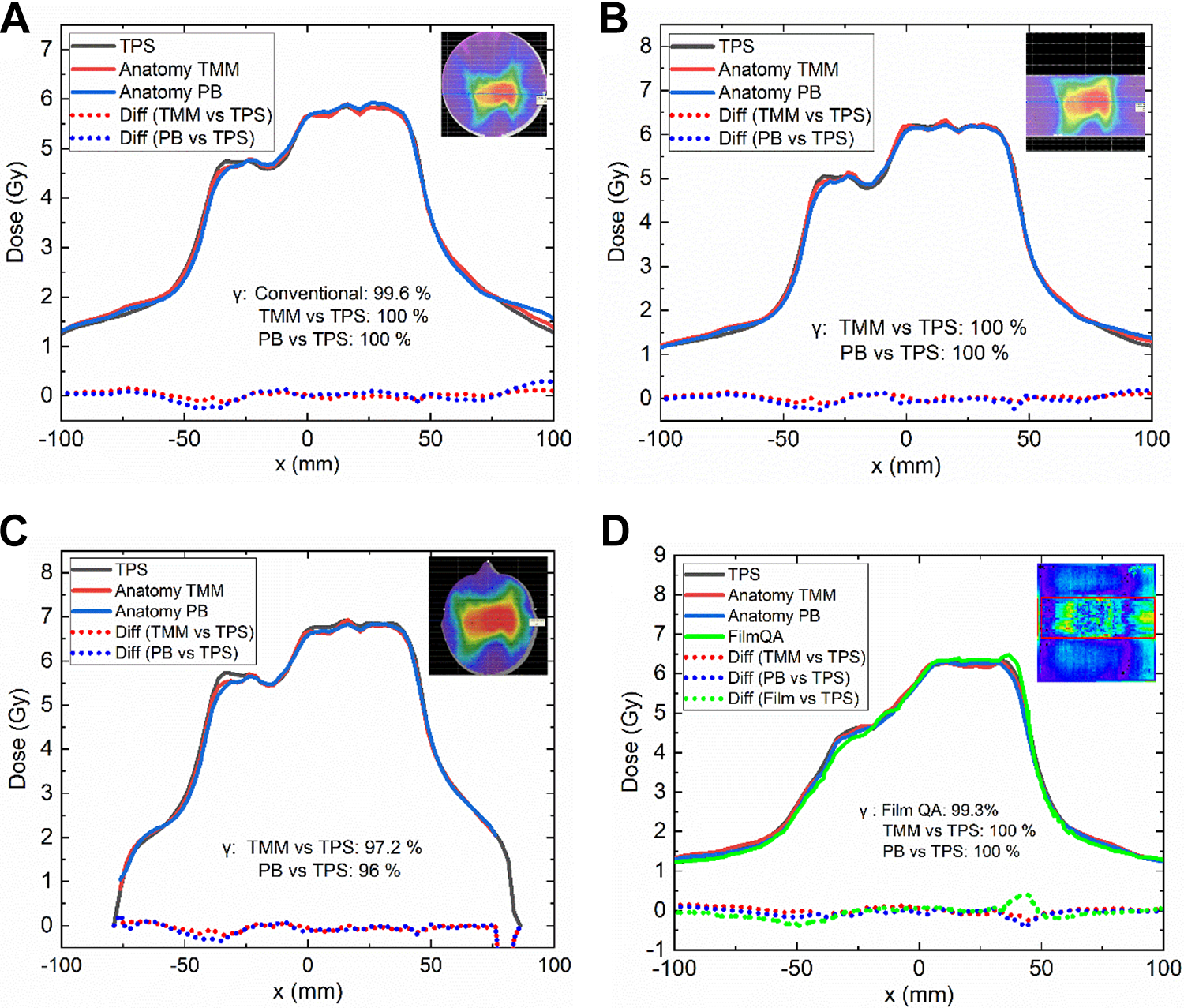
Gamma passing rate (GP) results and representative dose profiles’ comparisons in (A) Delta4 phantom; (B) slab phantom; (C) head and neck phantom; (D) the film QA results and dose profiles’ comparisons for TPS doses, Anatomy doses and film doses in slab phantom. QA indicates quality assurance; TPS, treatment planning system.
The conventional gamma analysis for Delta4 measured showed a GP of 99.6%. For Anatomy doses, all points passed the gamma analysis for TMM and PB calculations in the Delta4 phantom. The dose profiles of both Anatomy TMM and PB calculations agreed well with those of TPS calculations.
For film QA in the slab phantom, the film doses showed a GP of 99.3%, which was comparable to 100% for both TMM and PB. The dose profiles reconstructed with both TMM and PB exhibited reasonable agreement with the film dose profiles and TPS dose profiles.
For the head & neck phantom, the Anatomy GP dropped to 97.2% and 96% for TMM and PB calculations, respectively. The dose profiles of TMM calculations and PB calculations also agreed well with those in TPS.
Patient-Specific QA
Table 1 summarizes the point dose deviations for the 10 patient QA plans. The averaged difference between the ion chamber measured doses and the planned doses were 0.09% ± 1.17%. For Delta4 geometry, when compared to the TPS point doses, the Anatomy TMM doses and PB doses for the point corresponding to the reference point of ion chamber (21.2, 0, and 21.2 mm off the isocenter) showed a mean deviation of 0.48% ± 1.47% and −0.4% ± 1.54%, respectively. For patients’ geometries, the TMM point doses and PB point doses compared to TPS point doses showed a mean deviation of −0.57% ± 2.65% and −2.36% ± 2.38%, respectively.
The Averaged Dose Deviations (Mean ± SD [%]) for Ion Chamber Doses Versus TPS Doses, Anatomy Doses Versus TPS Doses for Both Delta4 Geometry and Patients’ Geometries for the Patient QA Plans.

Abbreviations: PB, pencil beam; QA, quality assurance; SD, standard deviation; TMM, treatment plan dose measured modification; TPS, treatment planning system.
Table 2 presents the gamma analysis results for the patient QA plans. The averaged conventional GP is 99.60% ± 0.89%. For the Anatomy doses in Delta4 geometry, the averaged GP for TMM versus TPS and PB versus TPS was higher than 98%. For Anatomy doses in patients’ geometries, the averaged GP for TMM versus TPS was 97.75% ± 1.23%. It dropped to 93.04% ± 2.69% for PB versus TPS. According to our local protocol for patient-specific QA, a plan is acceptable if the GP is higher than 95% for the criteria of 3 mm/3%. For Anatomy gamma analysis for PB versus TPS, 8 out of 10 plans failed to meet the action level of GP.
The Averaged Conventional and Anatomy Gamma Passing Rate Results (Mean ± SD) for the Patient QA Plans.

Abbreviations: PB, pencil beam; QA, quality assurance; SD, standard deviation; TMM, treatment plan dose measured modification; TPS, treatment planning system.
Figure 4 shows 3 examples of comparisons for Anatomy versus TPS dose profiles in Delta4 phantom and patients’ geometries. In these cases, good agreements were found between Anatomy TMM calculations and TPS calculations in both Delta4 and patients’ geometries. The PB calculations exhibited reasonable agreements with TPS doses in Delta4 geometry. However, substantial differences were observed in patients’ geometries.

Absolute dose profiles in TPS and Anatomy TMM and PB calculations: a VMAT plan for head&neck case in (A) Delta4 phantom and (B) real patient’s geometry; an IMRT plan for lung case in (C) Delta4 phantom and (D) real patient’s geometry; an IMRT plan for sigmoid colon case in (E) Delta4 phantom and (F) real patient’s geometry. IMRT, intensity-modulated radiotherapy; PB, pencil beam; TMM, treatment plan dose measured modification; TPS, treatment planning system.
Dose–Volume Histogram Metrics Comparisons for Error-Free and Error-Induced Plans
Table 3 presents the mean value of the DVH metrics in the TPS and the percentage difference between the reconstructed and planned DVH metrics for the 6 original plans. The types of DVH metrics were classified according to the value. The percentage DD of the DVH metrics for TMM versus TPS ranged from −1.95% to 2.30% with a mean value of 0.06% ± 1.26%. Nearly 30% of DVH metrics exhibited percentage differences higher than 3% for PB versus TPS, giving a mean value and a standard deviation of −1.82% ± 2.17%.
The Mean Doses and the Dose Differences Between Reconstructed and Calculated DVH Metrics for 6 Original Treatment Plans.

Abbreviations: BS, brain stem; DVH, dose–volume histogram; LFH, left femoral head; LL, left lung; PB, pencil beam; RL, right lung; RFH, right femoral head; SC, spinal cord; SI, small intestine; TMM, treatment plan dose measured modification; TPS, treatment planning system.
The box plots in Figure 5 present the percentage differences between the reconstructed and planned DVH metrics for the error plans. Again, almost all the absolute percentage dose differences for TMM versus TPS (black boxes) were within 3%, while a considerable amount of dose differences for PB versus TPS (red boxes) were higher than 3%.
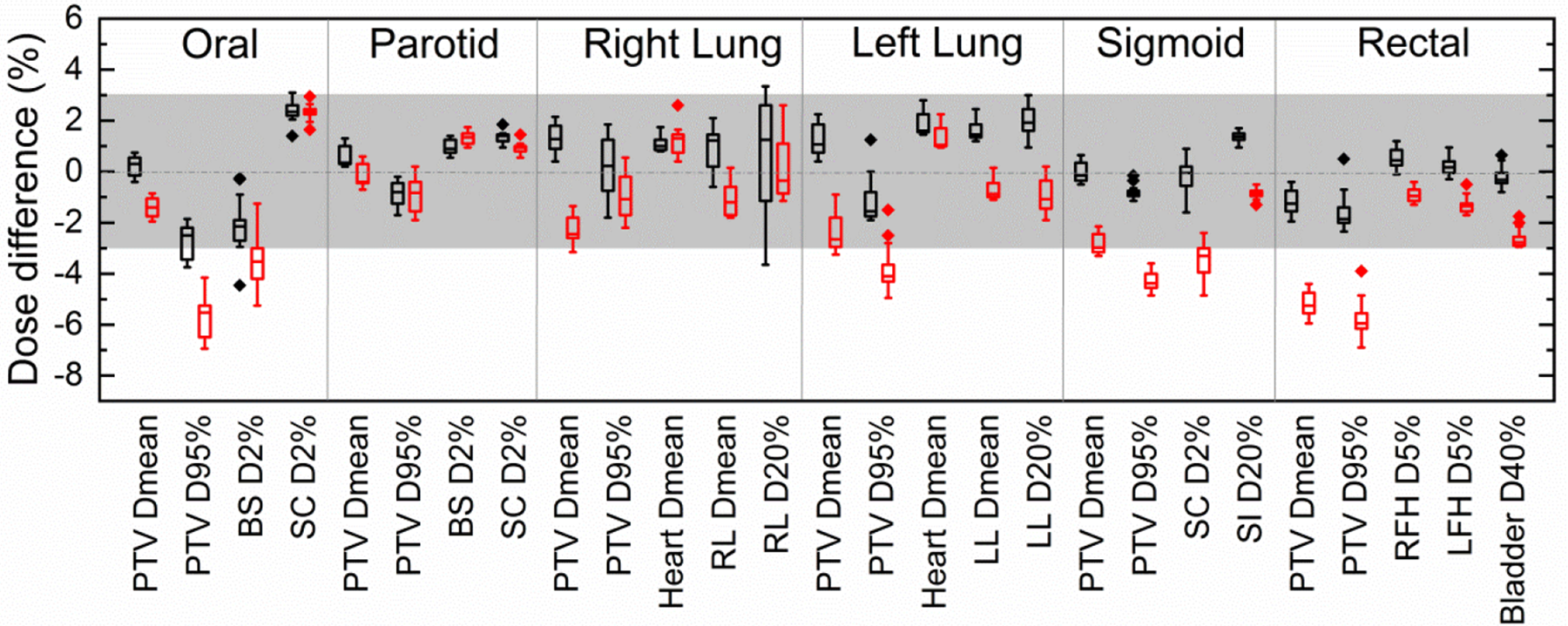
Box plots of the difference between reconstructed and planned DVH metrics. The box lines show the first quartile, median, and third quartile. The top and bottom whiskers extend to the maximum and minimum values, respectively. The black boxes and red boxes represented for the results for TMM versus TPS and PB versus TPS, respectively. PB indicates pencil beam; TMM, treatment plan dose measured modification; TPS, treatment planning system.
Results of the Pearson correlation coefficients (r values) and the slope of the linear regression lines for the reconstructed and the planned dose errors are shown in Table 4. As an example, Figure 6 presents the reconstructed versus planned dose errors for 2 cases. For the plans with MLC and MU errors, the linear regression analyses exhibited excellent linearity between the Anatomy TMM dose errors and TPS dose errors since the slopes were near 1 and the intercepts were near zero with r values close to 1 (an ideal fit would have an expected slope = 1, intercept = 0, and r = 1). The reconstructed dose errors for plans with gantry or collimator rotation errors did not imply strong correlations with the planned ones. The correlation analysis and linear regression results for PB versus TPS were similar to TMM versus TPS, except that the PB dose errors exhibited a weak correlation to the introduced MU errors for low dose metrics.
The Correlation Analysis Results and the Slopes of Linear Regressions for the Reconstructed and Planned Dose Deviations for the DVH Metrics.

Abbreviations: DVH, dose–volume histogram; MLC, multileaf collimator; PB, pencil beam; TMM, treatment plan dose measured modification; TPS, treatment planning system.

Reconstructed dose deviations versus TPS dose deviations caused by (A) and (B) MLC misalignment for the left lung case; (C) and (D) MU errors for the rectal case. MLC indicates multileaf collimator; TPS, treatment planning system.
The impact of these 4 types of errors to the patient dose distribution was different. The dosimetric impact of the MLC and MU errors on the DVH metrics was more apparent than that of collimator and gantry angle errors. The dose deviations of DVH metrics due to collimator and gantry errors considered in this study were less than 2%. Besides, the impact of the introduced errors to the DVH metrics varies from structure to structure. Concerning a 2 mm MLC opening error could lead an increase of the mean dose of PTV by 8.50%, while it resulted in an increase of 1.65% for the mean dose of heart in the lung cancer case in Figure 6A and B.
Discussion
The patient dose reconstruction based on the phantom measurements has recently gained popularity in the patient QA procedures. An accurate dose reconstruction method allows clinicians to evaluate the clinical relevance of the QA results. This study will help physicians and medical physicists to be aware of the features and the constraints of the Delta4DVH Anatomy in patient QA.
In this study, various plans were evaluated for both homogeneous and inhomogeneous phantoms. Good agreements of the ion chamber measured doses, film doses, Delta4 measured doses with TPS doses further validate the TPS calculations. Both TMM and PB calculations exhibit good agreements with film QA results in the homogeneous slab phantom. Only small differences are found in Anatomy TMM versus TPS doses and PB versus TPS doses in both Delta4 and slab phantom. These results indicate that both TMM and PB algorithms could provide satisfactory reconstructed doses in homogeneous phantoms.
Treatment plan dose measured modification doses agree well with TPS doses in not only homogeneous phantoms but also inhomogeneous geometries. According to the schematic of TMM dose calculation shown in Figure 2, a large amount of TMM dose is from TPS patient dose, the dose modification in the patient’s geometry is calculated with the PB algorithm only if the linac delivered doses are different from those in TPS. According to the evaulation results for error-induced plans, the most significant discrepancy of dose errors occurred in the case with 2 mm MLC misalignment, which leads to PTV mean dose deviation more than 8%. The TMM DVH could reflect the dose differences in this case. Besides, TMM calculations could also reflect the MU errors. This means that TMM algorithm is reliable in cases with MLC positional errors and output calibration errors. Since the PB algorithm has some issues with heterogeneity corrections, 23 the TMM dose calculations may not be very accurate when the value of dose modification is high. The situation regarding more substantial discrepancy between the linac and TPS calculations needs further investigations. It should be noted that, since the TMM dose calculation is dependent to the TPS calculation, the validation of TPS is critical before the implementation of the Anatomy TMM algorithm in patient-specific QA.
All plans meet the 95% action level with 3%/3 mm criteria for TMM versus TPS doses in this study. A similar study was carried out for Compass system, 12 showing that the averaged GPs for the whole body for 20 head&neck IMRT QA plans were 97.48% ± 0.21% and 91.88% ± 0.22% using criteria of 3%/3 mm and 2%/2 mm, respectively. In this study, the TMM reconstructions produced similar averaged GP of 97.75% using 3% / 3 mm criteria for all patient QA plans. However, the QA device and software used in this study were quite different, thus making a quantitative comparison is difficult.
For Anatomy PB calculations, the dose distributions agree well with TPS calculations in 2 homogeneous phantoms in the first VMAT plan. For the head & neck phantom, PB calculations pass the Anatomy gamma analysis with a GP of 96%, and the PB dose profiles agree with TPS calculations at an acceptable level. However, in the more heterogeneous patients’ geometries (eg, head&neck case and lung case), the disagreements tend to be more obvious. Larger discrepancies are also found in the regions of high dose gradients, suggesting that Anatomy PB algorithm may have issues in handling the heterogeneity and in penumbra regions. These findings are consistent with the previous study performed by Stambaugh et al, 15 who compared the dose distribution between Delta 4 PB calculations and ArcCHECK planned dose perturbation (ACPDP) calculations. Their studies demonstrated that the dose profiles and distributions calculated with Delta 4 PB algorithm showed poor agreement with those with ACPDP algorithm and TPS in heterogeneous CT data sets. The inaccurate dose calculations with Delta 4 PB algorithm were also reported by Hauri et al 16 in the border region of PTV and air-filled rectal balloon in prostate plans. The authors suggested a criterion of 5%/3 mm instead of 3%/3 mm in anatomy-based gamma analysis for the Anatomy PB dose calculations. Our evaluation results suggesting that TMM algorithm rather than the PB algorithm in Delta4DVH Anatomy is a more appropriate choice in the cases of heterogeneous sites.
Four types of errors were introduced, and then the dosimetric errors resulting from these errors were quantified. We find that the introduced dose errors were correctly calculated with the TMM algorithm for plans with MLC and MU errors. It is no surprise that the correlations between the reconstructed and planned dose errors are weak for the plans with gantry and collimator rotation errors. The weak correlations can be attributed to several factors. First, the dosimetric impact caused by the gantry and collimator angle errors is relatively slight in this study. This is consistent with the results reported by Viellevigne et al. 24 Besides, there might be small differences between the performances of the linac at the time of delivery of QA plans and those at the time of TPS commissioning, even though periodic QA is carried out to minimize the systematic errors. Furthermore, intrinsic errors are coming from the implementation of different dose calculation algorithms in the TPS and the Delta4DVH Anatomy. Therefore, the insignificant dose deviations caused by the gantry or collimator errors may be masked by the influence of the different algorithms or the systematic errors of the linac.
It should be noted that each structure has a unique sensitivity to the introduced errors. The sensitivity is likely to be affected by multiple factors such as the geometry of the patient’s body, the complexity of the fluence map, the size of the target volume, the distance to the radiation field. Addressing the question of how the manufactured errors influence the dose distributions in different structures needs more detailed analyses in the future. What’s more, the 3D anatomy-based dose verification raises new questions on topics, such as the correlations between the organ-specific GPs and the DVH metrics. Future efforts are also needed to establish an appropriate evaluation criterion in anatomy-based QA to determine if a plan is acceptable clinically.
This study has several limitations. First, the Anatomy doses were not compared to 3D measurements since the gel verification system is not available for our department so far. Second, the performance of Delta 4 system in reconstructing patient dose for stereotactic body radiation therapy (SBRT) plans was not evaluated in this study. Since the field sizes are comparable to the pitches of detectors of Delta, 4 the dose reconstruction results for SBRT plans may be affected by the resolution of the detector arrays. Therefore, a more detailed investigation is needed and will be carried out in the future. In addition, limited types of errors were used in this study. Other types of errors might occur as well, and thus future work will expand the evaluations to a variety of errors.
Conclusions
Based on the evaluation results, we conclude that the Delta4DVH Anatomy with TMM algorithm is a suitable tool for measurement-based patient dose reconstruction. The PB algorithm is not recommend since it has issues in handling inhomogeneity and in penumbra regions.
Footnotes
Acknowledgments
The authors would like to express their gratitude to Madeleine Holm, Erik Bängtsson (ScandiDos AB Co.), and Guanyuan Liu (HGPT Co.) for their assistance during the commissioning of Delta 4 system and their helpful suggestions on the manuscript.
Declaration of Conflicting Interests
The author(s) declared no potential conflicts of interest with respect to the research, authorship, and/or publication of this article.
Funding
The author(s) received no financial support for the research, authorship, and/or publication of this article.