
Abstract
Objective:
To compare differences in setup error assessment and correction between planar kilovolt images and cone beam computed tomography images for external beam partial breast irradiation during free breathing.
Methods:
Nineteen patients who received external beam partial breast irradiation after breast-conserving surgery were recruited. Interfraction setup error was acquired using planar kilovolt images and cone beam computed tomography. After online setup correction, the residual error was calculated, and the setup error was compared. The residual error and setup margin were quantified for planar kilovolt and cone beam computed tomography images.
Results:
The largest setup error was observed in the anteroposterior direction for both cone beam computed tomography and planar kilovolt imaging (−1.45 mm, 1.74 mm). The cone beam computed tomography–based setup error (systematic error [Σ]) was less than the planar kilovolt images based on Σ in the anteroposterior direction (–1.2 mm vs 2.00 mm; P = .005), and no significant differences were observed for random error (σ) in 3 dimensions (P = .948, .376, .314). After online setup correction, cone beam computed tomography significantly reduced the residual setup error compared with planar kilovolt images in the anteroposterior direction (Σ: −0.20 mm vs 0.50 mm, P = .008; σ: 0.45 mm vs 1.34 mm, P = .002). The cone beam computed tomography–based setup margin was smaller than the planar kilovolt image-based setup margin in the anteroposterior direction (−1.39 mm vs 5.57 mm, P = .003; 0.00 mm vs 3.20 mm, P = .003).
Conclusions:
Discrepancy between the setup errors observed with planar kilovolt and cone beam computed tomography was obvious in the anteroposterior direction. Compared to cone beam computed tomography, the elapsed treatment time was smaller when the initial alignment used kilovolt planar imaging. Whether using planar kilovolt or cone beam computed tomography, residual errors can be reduced to 1.5 mm for external beam partial breast irradiation procedures.
Keywords
Introduction
Image-guided radiation therapy (IGRT) exposes breast tissue to homogeneous radiation doses and does little damage to healthy tissues and organs at risk. 1 -4 Online or offline setup error (SE) measurement and correction is an important component of IGRT and is a daily practice before radiotherapy for both whole-breast irradiation (WBI) and external beam partial breast irradiation (EB-PBI). Important tools for patient SE measurement and correction in radiotherapy include electric portal imaging devices (EPIDs), orthogonal kilovolt X-ray plane film, and cone beam computed tomography (CBCT). 5 -8
There are several factors leading to target position uncertainty during patient irradiation, of which patient intrafraction displacement and interfraction variability are the most important. In addition to cardiac and digestive system motion, tumor regression, and breast shape changes, SE is the primary cause of interfraction displacement. Hector et al 9 reported that for patient with breast cancer treated with radiotherapy using EPID as a component of breast-conserving treatment, a significant increase in breast volume beyond the 95% to 105% dose range was observed when the superior–inferior (SI) and anterior–posterior (AP) direction SEs were greater than 3 mm. Setup error includes the variation between the planned position and the average position upon repositioning, as well as the fraction to fraction variations around the mean deviation. Therefore, SE can impact the clinical target volume (CTV) and planning target volume (PTV) margin and can also affect the dosimetric consequences during treatment. 9 Topolnjak et al 5 demonstrated that EPID registration underestimated the actual bony anatomy SE by 20% to 50%. For patients with breast cancer treated postoperatively with the simultaneous integrated boost technique, CBCT significantly reduced setup uncertainties. The use of CBCT image guidance during radiotherapy for precise localization of target volume and accurate setup correction has become routine for whole-breast radiotherapy.
Although EB-PBI is not the current standard of care, it can reduce the overall treatment time to approximately 1 week while maintaining good local control. Thus, EB-PBI is suitable for patient selection. 10 -12 Accurate localization of the target volume for each treatment fraction is important during EB-PBI because of hypofractionation and accelerated treatment that make IGRT desirable for clinical processes. However, some reports have focused on image guidance techniques based on 2-dimensional (2D, projective) or 3-dimensional (3D, volumetric) X-ray imaging data for WBI, 5,8 while only a few for EB-PBI daily fraction treatment monitoring by different matching methods. 13 Over this shorter treatment time, the sensitivity to SE and residual error assessment using image guidance techniques based on 2D versus 3D imaging is unresolved. The purpose of our study was to compare the differences in SE assessment and correction between planar kV imaging and 3D-CBCT imaging in patients treated with EB-PBI during free breathing. Our hope is that the results of this study will provide the basic data needed to determine the best method to achieve online setup correction for EB-PBI, allowing the calculation of appropriate setup margins (SMs) after SE correction in each direction with planar kV and CBCT images, for precise irradiation using a 3D treatment planning system.
Materials and Methods
Patient Selection and Instruction
All of the recruited patients with early breast cancer were treated with lumpectomy and sentinel node and/or lymph node dissection and were suitable for postoperative treatment with EB-PBI in our department. Patients with poor pulmonary function or restricted arm movements after surgery were excluded. The institutional research ethics board of Shandong Cancer Hospital approved this study (SDTHEC201603029), and written informed consent was obtained from all of the patients.
Nineteen patients who received EB-PBI after breast-conserving surgery (BCS) were enrolled in this study. All of the patients were diagnosed with an invasive ductal carcinoma. Fifteen patients exhibited left-side breast cancer, and the remaining 4 had right-side breast cancer. The mean patient age was 52 years (range, 45-60 years).
At the time of simulation, patients were immobilized and aligned in the supine position on a breast board, with both arms raised overhead and positioned on the arm support device. Knee supports were placed under the knees to fix the position and improve patient comfort. The free breathing 3-dimensional CT scans were acquired on a 16-slice CT scanner (Philips Medical System, Cleveland, Ohio, USA). The standard acquisition parameters of the 3DCT were 120 kV and 200 mA. The 3D CT scans were produced per gantry rotation (1 second) and interval (1.8 seconds) between rotations. The slice thickness of the 3D CT scan was 3 mm. Three laser alignment lines were marked on the patient before CT acquisition.
Planning Target Volume Definition and Planning Design
The tumor bed (TB) boundaries were defined using a combination of breast tissue changes that were apparent using CT simulation, pathological and radiographic information, fluid collection within the TB, and the number of surgical clips. The CTV is a 10-mm expansion around the TB that should not extend outside of the body (restricted to 5 mm from patient surface) or into the pectoralis muscles and/or muscles of the chest wall. A CTV with a 5-mm expansion based on setup uncertainty and predicted patient motion was considered the PTV. Patients were treated with 10 fractions × 3.4 Gy delivered twice per day, and 3D conformal radiotherapy (3D-CRT) with 6 MV photons in a 4-field noncoplanar beam arrangement was employed. And all the treatment plans were transferred to 4DITC of Clinac Trilogy Linear Accelerator equipped with On-Board Imager (Varian Medical Systems, Palo Alto, California, USA).
Cone Beam Computed Tomography and Planar kV Images
The patients were aligned according to the skin tattoos by using the in-room laser system in the treatment position. Then online IGRT alternate between kilovoltage CBCT scanner (kV CBCT; Varian Medical Systems, Palo Alto, California, USA) and planar kV images (orthogonal kilovolt X-ray plain film; Varian Medical System) every other fraction were acquired before radiotherapy. Because radiotherapy sessions consisted of 10 fractions for each patient, a series of 5 CBCT images and 5 planar kV images were acquired to verify setup accuracy. Planar kV and CBCT images were obtained on separate fractions (planar kV for the 1st, 3rd, 5th, 7th, 9th; and CBCT for the 2nd, 4th, 6th, 8th, and 10th.): 5× we performed planar images, then corrected the SE, and again took planar images, and 5× a CBCT was made, then the position adjusted, and again a CBCT made.
Full-fan CBCT scans were acquired using a kilovoltage CBCT scanner (Varian Medical Systems) with the patient in the treatment position. The standard acquisition parameters were 120 kV and 1000 mA. The iodinated contrast medium was infused at a rate of 1.8 mL/s. The scan time was approximately 1 minute. Cone beam computed tomography is registered to planning CT and planar kV image is registered to digitally reconstructed radiographs (DRRs) at the planning which were solely rely on automatic matching. The discrepancy between planned and actual treatment position was automatically evaluated using the software accompanying the Trilogy Linear Accelerator. Thus, the interfraction displacement of each patient in 3 dimensions was acquired based on the shift between the setup position and the final treatment position. Then the position adjusted and again a CBCT or planar kV made CBCT- and planar kV-guided positioning residual setup shifts were recorded in the lateral (LR), AP, and SI directions.
Setup Error and SM
For each patient, the difference in mean shifts in each direction was compared. For each patient, the mean and standard deviation (SD) of all recorded errors were calculated. Subsequently, these interfraction displacements were used to obtain the overall group mean SE (M, which is the average over all patients’ mean shifts), the systematic SE (Σ, which is the SD over group mean error), and the random SE (σ, which is defined as the root mean square of the patients’ SDs). To determine any benefits between the 2 image modalities after implementing online setup correction, the residual SE was also calculated. The systematic and random SE after online setup correction was calculated as the residual error (M, Σ, and σ). The SMs were calculated based on the formula from van Herk as follows: 14,15

Statistical Analysis
Statistical analysis was performed using the SPSS statistical analysis software package (SPSS Inc, Chicago, Illinois). Wilcoxon signed rank tests were performed to determine the statistical significance of differences in SE, residual error, and SM quantified for planar kV and CBCT depending on the normality of the data. For all of the statistical tests, statistical significance was established as P < .05.
Results
Setup Errors
A total of 190 CBCTs and 190 planar kV images were performed. All 19 patients received 5 CBCTs and 5 planar kV images before online setup correction, and 5 CBCTs and 5 planar kV images were acquired after on-line setup correction during EB-PBI.
The analysis was performed based on the premise that planar kV and CBCT images from the same patient were obtained in the same position. The results for the SE (M, Σ, and σ) are presented in Table 1. We found that the largest SE was observed in the AP direction for both CBCT and planar kV (−1.45 mm, 1.74 mm). The CBCT-based SE (systematic error, Σ) was less than the planar kV-based Σ in the AP direction (−1.2 mm vs 2.00 mm; P = .005). For each patient, the mean random SE observed using planar kV images did not differ from that observed with CBCT images in all 3 dimensions (P = .948, .376, and .314; LR, AP, and SI, respectively).
Setup Error Characteristics: Assessment of Differences Between Planar kV and CBCT in 3 Dimensions (mm).

Abbreviations: AP, anteroposterior (posterior = negative, anterior = positive); LR, lateral (left = negative, right = positive); M, mean setup error; SI, superoinferior (inferior = negative, superior = positive); Σ, systematic setup error; σ, random setup error.
Setup Residual Error
After online setup correction, the setup residual errors (M, Σ, and σ) for each image modality were calculated in 3 dimensions, as presented in Table 2. The setup residual errors observed for both the planar kV and CBCT images were reduced compared with the SE (M, Σ, and σ) before online setup correction. The CBCT approach decreased the system setup residual error (Σ) more significantly than planar kV only in the AP direction (−0.20 mm vs 0.50 mm, P = .008). Regarding random setup residual error (σ), significant differences (P = .022, .002) were noted between planar kV and CBCT images in the LR and AP directions. The random setup residual error observed in the CBCT images was less than for planar kV (LR: 0.55 mm vs 1.10 mm; AP: 0.45 mm vs 1.34 mm).
Residual Setup Error Characteristics: Assessment of Differences Between Planar kV and CBCT in 3 Dimensions (mm).
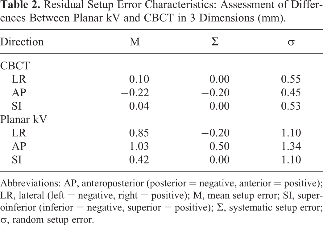
Abbreviations: AP, anteroposterior (posterior = negative, anterior = positive); LR, lateral (left = negative, right = positive); M, mean setup error; SI, superoinferior (inferior = negative, superior = positive); Σ, systematic setup error; σ, random setup error.
Setup Margin
The SM for each image modality was calculated using van Herk’s formula 14,15 based on random and systematic SEs (Table 3). We observed that regardless of whether online setup correction was performed, CBCT-based SM was lower than the planar kV image-based SM in the AP direction (before online setup correction: −1.39 mm vs 5.57 mm, P = .003; after online setup correction: 0 mm vs 3.20 mm, P = .003).
Setup Margin Characteristics: Assessment of Differences Between Planar kV and CBCT in 3 Dimensions (mm).

Abbreviations: AP, anteroposterior (posterior = negative, anterior = positive); LR, lateral (left = negative, right = positive); M, mean setup error; SI, superoinferior (inferior = negative, superior = positive); Σ, systematic setup error; σ, random setup error.
Discussion
Ultrasound (2D-US and 3D-US), CT imaging, magnetic resonance imaging, X-ray plain film (planar megavoltage images and planar kV images), and CBCT are major tools used to localize tumors in patients and monitor progress in patients over the course of radiotherapy, 4,5,7,8 which can be used to examine the displacement of the lumpectomy cavity online or offline during the treatment. Our work demonstrates that the SEs observed for both planar kV and CBCT images were less than 2 mm in all 3 dimensions. Chopra et al 16 found that the mean setup deviation was 1.3 mm, 1.3 mm, and 4.4 mm in the LR, SI, and AP dimensions, respectively, during normal breathing. Surgical clips within the lumpectomy cavity, the breast surface, the chest wall, and radiopaque skin markers can be used as registration surrogates for detecting the lumpectomy cavity and lumpectomy cavity displacement during radiotherapy. These results suggest that clip alignment and registration improved localization compared with other registration methods and was considered more effective. 13,17 -19 However, directional differences for the intrafraction displacement of the surgical clips were noted within the lumpectomy cavity. 20 -22 Hence, our study used automatic image matching to decrease the disparity of different matching standards or mode selections for different patients and for more than one registration.
Cone beam computed tomography are 3D volumetric images, which may cover up part of the target displacement. We demonstrated that the SE acquired by planar kV imaging exceeded that acquired by CBCT in the AP direction. Moreover, in the SI and LR directions, the mean residual SE was not different for planar kV and CBCT images. Similar to thoracic neoplasms, Martins et al have proved that the mean SE observed with kV images differs from that observed with CBCT in the LR direction for each patient with esophageal cancer. 23 While, for prostate and head and neck cancer, Dzierma et al 24 observed larger systematic errors for kV CBCT in the SI and LR directions compared with planar imaging. These variations resulted from a number of factors: (1) Differences in tissue density, anatomic location, and scanning position of the images. (2) The time for CBCT acquisition is greater than 60 seconds, which encompasses several respiratory cycles. The hysteresis of the scanning image during different respiratory cycle may reduce CBCT detection efficiency when evaluating SEs in the AP direction. (3) The accuracy of interfraction displacement acquired between 2D dimensional orthogonal kilovoltage images (2D-kV) and 3-dimensional visualization images used for IGRT also exhibits differences. (4) The TB was correlated better with the breast surface in all directions, while this was statistically significant in the AP direction. 25
As long as proper and precise immobilization is used, the image-guided online or offline correction can be performed as the main procedure before each radiotherapy fraction for SE correction and to minimize the CTV to PTV margin. 4,5,7,8,18 Although online or offline correction minimizes SEs, residual error still exists. Several factors cause residual error: the uncertainty of automatic image alignment, the subjectivity of manual image alignment, the limitations of equipment precision, and patient movement during radiotherapy. Additionally, residual errors remain present after setup correction because rigid registration cannot correct the target deformation, the anatomical movement of normal tissue, and the treatment target. Our study demonstrated that compared with kV planar, residual error was reduced by 60% after setup correction by CBCT. Although the residual SE was reduced by 1.5 mm using kV planar image correction, both the random and systematic residual SE differences between the 2 ranged from 0 to 0.9 mm in 3D. Fatunase et al 26 used CBCT to assess the residual error in soft tissue after kV/MV alignment based on bony anatomy. They found that the root mean square of the residual error was 3, 4, and 4 mm in the RL, AP, and SI directions, respectively. Discrepancies between ours and Fatunase et al might be caused by ethnic differences, the fact that the breast sits on the chest and is not a fixed structure, as European and American breasts are larger than Asian breasts, interfraction displacement, 7,27 and different experimental techniques.
Cox et al 28 studied the use of 3D-CRT for accelerated partial breast irradiation (APBI). For each 5-mm increase in the CTV to PTV margin, the ratio of PTV to total breast volume increased by 10%, and the relative increase in the mean ipsilateral breast dose was 15%. For patients who accepted whole-breast beamlet intensity-modulated radiation therapy, Acharya et al 1 have found that the mean (±SD) difference between planned and delivered dose to the PTV (V95) was 0.6% ± 0.1% for EB-PBI. And the residual and intrafractional errors can also significantly affect the accuracy of image-guided APBI with nonplanar 3D-CRT technique. 29 Our study demonstrated that after CBCT and kV planar correction, the SM was reduced to less than 1.0 and 3.5 mm, respectively. A CBCT or kV planar online correction should be performed before each fraction to minimize SE when smaller CTV-PTV margins are recommend. When CBCT registered to planning CT imaging or kV planar imaging registered to DRRs was used for SE correction, the SM values in the AP direction differed. Therefore, CTV to PTV margins should consider movement in different respiratory states, interfraction displacement induced by setup (patient positioning variability and shape changes of the breast), 21,22 whether SE correction was adopted, and the mode of SE assessment and correction.
When patients received EB-PBI after BCS during free breathing, largest SE was observed in the AP direction for kV planar imaging compared to CBCT imaging, while 3D-CBCT online correction decreased the setup residual error more than planar kV imaging in the AP direction. As reported in the literature, doses range from 0.2 to 2 cGy per kV-CBCT scan. 2,30 Therefore, the cumulative dose of kV CBCT before each treatment (a total of 10 fraction) remained acceptable for patients receiving EB-PBI. The time for CBCT acquisition and image reconstruction is approximately 1.5 minutes. Thus, the therapy time was obviously increased compared with kV planar. And also with a lower dose to the patient, planar kV images are also more rapidly acquired than CBCT 23,31 and can be used for breast IGRT. For patients with breast cancer who received radiotherapy, the tension of the breast skin can influence patient positioning. In addition, with elapsed therapy time, variations in arm position also cause changes to the tension of the treated skin. Shorter positioning and treatment times also should be highlighted for patients with breast cancer. In patients treated with EB-PBI, residual errors can be reduced to 1.5 mm.
Footnotes
Authors’ Note
Wei Wang and Ting Yu contributed equally to this work.
Acknowledgments
This manuscript was edited by American Journal Experts (AJE).
Declaration of Conflicting Interests
The author(s) declared no potential conflicts of interest with respect to the research, authorship, and/or publication of this article.
Funding
The author(s) disclosed receipt of the following financial support for the research, authorship, and/or publication of this article: The National Key Research Program of China (No. 2016YFC0904700), National Natural Science Foundation of China (No. 81 703 038 and No. 81 502 314), The Natural Science Foundation of Shandong Provence (No. ZR2017PH006), The Key Research Development Program of Shandong Province (No. 2017GSF18102), The Science and Technology Program of Xinjiang Uygur Autonomous Region (No. 2017E0260).