
Abstract
Weld seam connection is a common form of connection for the main stress joints in membrane structures. However, current research overlooks the impact of off-axis angles of coated fabric on stress distribution. To thoroughly understand the welding connection performance and tensile failure mechanisms, this paper investigated the tensile properties of PVC-coated fabrics with single-layer off-axis patch and double-layer off-axis patch. The effects of off-axial angle, overlapping connection method, and weld width on tensile strength and elongation at break were examined. The results indicate that, as the off-axis angle varies, the tensile strength and elongation at break of the coated fabric welding-covered connection specimens display two distinct trends. According to Digital image correlation (DIC) testing, warp patch coverage is beneficial for the coordinated stress and reasonable distribution of strain field in the coated fabric. In the design of PVC-coated fabric connection with weld seam cover treatment, it is necessary to consider the strength reduction at the welding site based on the connection type, weld width, and off-axis angle. Double-layer connections with patch widths exceeding 70 mm are recommended when the substrate material and patch are in warp-weft orientation; For off-axis designs, a 45° material offset angle may be adopted with patch widths greater than 50 mm.
Introduction
Membrane structures, widely used in high-speed railway platforms and large airports, offer significant advantages such as efficient space utilization and strong architectural expression. 1 The membrane structures enhance the overall stiffness of the system by resisting external loads through increased pre-tension. 2 Coated fabric is a common material used in membrane structures. It mainly consists of a fiber-based fabric and a surface coating. The warp and weft fiber bundles are woven according to the weaving method to form a fiber-based fabric. Among them, PVC coated fabrics are widely used due to their significant advantages in material strength and price. 3 Nowadays, the mechanical properties of coated fabric have been widely studied by scholars at home and abroad, including uniaxial tensile properties, 4 biaxial tensile properties,5,6 shear properties, 7 tearing properties8,9 and kinetic properties.10–13 Several models have been developed to describe the complex mechanical behavior of these materials.14,15 Due to the complex weaving process and mechanical behavior of the membrane material, it shows significant nonlinearity. 16
In practical construction, the width of coated fabric is limited. Therefore, it is necessary to cut and join the membranes before connecting them to the supporting structure. This process forms a complete and safe three-dimensional curved surface.
17
These joints include connections between coated fabrics, connections between coated fabric and cables, and connections between coated fabric and boundaries. Heat-sealing welding is a common joining method for coated fabrics. In practical engineering, various welding configurations can be employed depending on connection requirements.18,19 As illustrated in Figure 1, this paper focuses on two typical butt-welding configurations: butt-welding with single-layer patch and butt-welding with double-layer patch. These two methods are commonly used in connecting PVC-coated fabrics.20–22 Due to process deviations during welding and curvature variations in the membrane surface, butt-welding joints are typically subjected to complex tensile-shear coupled stress states. The performance of these joints directly affects the safety and reliability of membrane structures throughout their service life.23,24 Despite the non-weldability of coated fabric surfaces limiting its applications, existing studies lack systematic analyses quantifying its effects on joint strength and failure modes at the substrate material level. At the same time, systematic research on butt welds can clarify the limiting scenarios for their reasonable use and prevent misuse in traditional practice. Welded seams of coated fabric. (a) Butt-welding with single-layer patch. (b) Butt-welding with double-layer patch.
The welding methods for different coated fabrics vary significantly due to their distinct thermal properties. PVC-coated fabrics are usually joined using high-frequency welding. This method uses electromagnetic energy to internally heat the material, causing the PVC coating to melt and bond under pressure. PTFE-coated fabrics, which require a different approach, are welded using high temperatures and fluoropolymer adhesives such as FEP films. The welding process of PTFE relies on external heating and pressure to melt the adhesive interlayer. Under out-of-plane tensile forces, bonded joints mainly show adhesive failure. This typically manifests as either interfacial separation at the adhesive interphase or delamination between the polymeric coating and textile substrate. Properly designed fusion joints can reach more than 80% of the base material’s strength in in-plane shear tests. 25 However, their resistance to tensile peel forces is much lower. 26 Multiaxial stress analysis confirms that peel failure mechanisms become predominant under combined tension-shear loading scenarios. Current industrial standards provide established protocols for assessing in-plane shear peel characteristics in textile composites, but membrane engineering still lacks standardized test methods for peel resistance.27,28 It is difficult to reliably evaluate the comprehensive performance of key connections in membrane structures under the combined tensile and shear loads of hot melt joints.
Thermal bonding is the primary method for connecting force seams between diaphragms. Existing thermal bonding technologies can achieve connections with equal strength between the diaphragms. However, the performance of these thermal bonds or adhesions may degrade significantly due to the influence of the service environment. Li et al. 29 investigated the mechanical properties and stress mechanisms of various diaphragm-to-diaphragm welded seams. Shi et al. 30 compared the tensile strength parameters of different thermal welded seams and examined the tensile failure mechanisms of thermal connections in capsule materials. Zhao et al. 31 analyzed the effects of different ambient temperatures on the failure modes, strength, and deformation properties of welded seams. Chen et al. 32 explored the impact of welded strips with different material properties on the strength of structural skins. Wang et al. 33 studied the uniaxial tensile properties of GQ-6 skin material under varying welding lengths. Ji et al. 34 examined the effects of cyclic loading on the mechanical properties of welded seam. These studies show that existing research on thermal bonding mainly focuses on uniaxial mechanical performance. Most of this work examines lap joints in the longitudinal and latitudinal directions. However, there is a limited exploration of thermal connections involving off-axis angles, and the effects of different connection forms have not been sufficiently explored. Furthermore, the cover connection form has received minimal attention in the existing literature.
This paper presented the results of uniaxial tensile tests on single-layer and double-layer welded seams of architectural coating fabrics. The tensile performance of the membrane seams was analyzed under different conditions. The influencing factors included off-axial angle, mulching method, and weld width. The investigation focused on how these factors affected tensile strength, elongation at break, and failure modes. Digital image correlation (DIC) technology was employed to measure strain distribution on the membrane surface, enabling a detailed analysis of tensile performance degradation and identification of damage failure modes in the membrane welded seams under complex stress conditions.
Materials and experimental methodology
Materials and specimens
Mechanical properties.

The specimens were prepared using the spline cutting method. The cutting positions were set at least 100 mm from the side edges and 300 mm from the bottom edge, which helped reduce the influence of wrinkles and defects in the raw material. The membrane specimens were cut into elongated strips, each with a total length of 1000 ± 1 mm, including 400 mm at each end reserved for winding. The effective length of the specimen was 200 ± 0.5 mm, with a width of 50 ± 0.5 mm. The final off-axis specimen configuration is shown in Figure 2. Material cutting and off-axis schematic.
The specimens were designed as elongated strips. The parameters of the single-layer patch specimens are shown in Figure 3 and the parameters of the double-layer patch specimens are shown in Figure 4. Parameters of single-layer patch specimens (unit: mm). Parameters of double-layer patch specimens (unit: mm).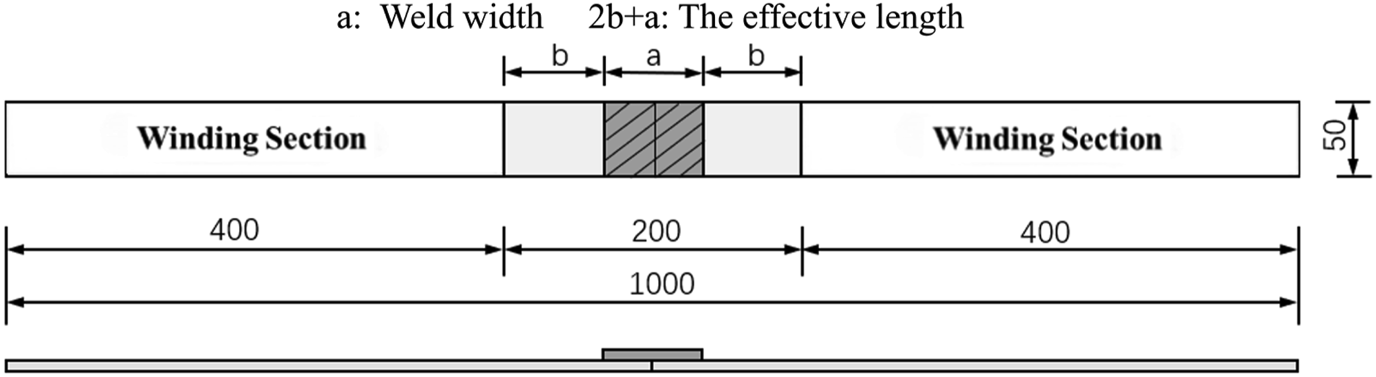

According to the design requirements of the weld sample, the PVC-coated fabric was cut and welded using a 25 MHz high-frequency welder. To ensure welded seam quality, the heat-sealing area was intentionally designed to be slightly larger than the target welding area. The welding time was maintained for at least 5 s to ensure uniformity and precision in the weld. Additionally, the weld length error was strictly controlled within 1 mm to prevent impurities and burning, ensuring compliance with industry standards.
To investigate the uniaxial tensile properties of welded seams in coated fabric, uniaxial tensile tests were conducted on specimens with single-layer and double-layer welded seams. For the single-layer patch specimens, seven off-axis angles of the substrate material—0°, 15°, 30°, 45°, 60°, 75°, and 90°—were selected. The covering patches at different off-axis angles have different material stiffness and fracture properties. To gain a deeper understanding of the failure mechanism of PVC-coated fabric, the alignment of the covering patches was varied across four configurations: pure coated fabric without overlay patch, parallel to the warp direction, parallel to the weft direction, form an off-axis angle consistent with the base material. The samples were labeled as “B weld width-angle”, “FJ weld width-angle”, “FW weld width-angle”, and “FA weld width-angle” according to the four configurations mentioned above. Additionally, for the double-layer patch specimens, weld widths of 30 mm, 50 mm, and 70 mm were tested. These specimens were designated as ‘SJ weld width-angle’ and ‘SW weld width-angle’, depending on the specific weld width. The cutting rules for the specimen of single-layer patch specimen are shown in Figure 5. Cutting of single-layer patch specimens.
Uniaxial tensile testing equipment
The specimens were secured with winding-type clamps. Uniaxial tensile tests were conducted using an electronic universal tensile testing machine, equipped with a high-precision load sensor to measure tensile forces and a large-deformation extensometer to monitor specimen elongation. The loading rate was set at 100 mm/min, and data were collected at a frequency of 10 Hz. The test setup is shown in Figure 6. Test setup.
Digital image correlation equipment
DIC technology was used to capture strain in the core area during the tensile process. It enabled non-contact, full-field measurement of the specimen along the warp direction during the entire test. The process began with the use of a high-definition camera to record the entire test procedure. Images at different time intervals were saved using Galaxy Viewer software. Then, 2D-Ncorr software on the MATLAB platform was used for deformation analysis. This provided full-field strain data within the measurement range, as shown in Figure 7. The analysis provided strain data for the membrane surface, including transverse strain (xx), longitudinal strain (yy), and shear strain (xy). Digital Image Correlation and test system.
The 2D-Ncorr strain analysis software requires the definition of specific coordinate axes. According to actual experiments, the horizontal direction is defined as the X-axis, and the vertical direction is defined as the Y-axis, as shown in Figure 8(a). Additionally, the software requires the selection of an initial reference image for strain analysis. In this paper, the undeformed specimen image was chosen as the initial reference, and four strain extraction points were evenly distributed within the speckle area, as shown in Figure 8(b). To account for potential deviations during the edge-cutting process and the possibility of slight divergence of the edge yarn during stretching, the strain extraction points were positioned away from the specimen edges. Therefore, the square part of the DIC test has been divided into four parts using horizontal and vertical centerlines, with the center point of each part selected as the stress extraction point (Figure 8(a)). 2D-Ncorr strain analysis software. (a)Coordinate system. (b) Software operation interface.
Experimental procedure
Before the experiment commenced, the prestress of the membrane specimen was set to 10 N. The DIC system was synchronized with the tensile testing machine to ensure accurate data collection. During the experiment, both the load-displacement curves and the observed experimental phenomena were recorded. To facilitate a detailed analysis of the deformation and failure mechanisms of the material, two specimens were random selected from each group for further examination. A grid pattern was drawn on each specimen using a marker pen, with one grid line aligned with the tensile direction and the other reflecting changes in fiber orientation at varying off-axis angles, as shown in Figure 9(a). A random black speckle pattern was applied in a 50 × 50 mm2 area at the center of each specimen (as shown in Figure 9(b)) to facilitate strain distribution measurement via the DIC system during the tearing process. Different marking modes of specimens. (a) Grid line, (b) Scattered class.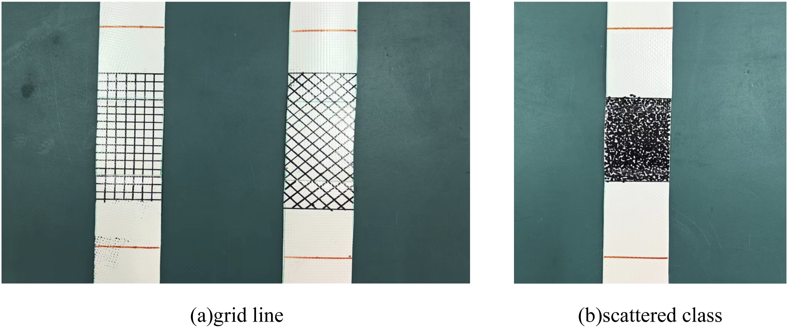
Two specimens were selected from each group, with each group tested five times, to ensure the reliability and validity of the experimental data. The tests were carried out under controllable environmental conditions with the temperature maintained at (20 ± 2)°C and the relative humidity maintained at (65 ± 4)%.
Results and discussions
Failure modes and mechanisms
The off-axis tensile failure modes of PVC-coated fabric with single-layer pach were categorized into three types (Figure 10). This classification is established by analyzing both the yarn stress distribution during tensile loading and the post-fracture failure patterns. These failure modes are: (1) fiber pull-out failure, (2) fiber fracture failure, and (3) coating peeling failure. Failure modes of weld single-cover specimens. (a) Fiber pull-out failure. (b) Fiber fracture failure. (c) Coating peeling failure 1, (d) Coating peeling failure 2.
The first failure mode is fiber pull-out failure. This failure occurs at the connection point of the two substrate material, where the middle cover patch material separates into two parts. The fracture surface exhibits a planar morphology. Both substrate and patch yarns demonstrate pull-out failure characteristics, as evidenced in Figure 10(a). When the weld width of the single-covered connection is 50 mm, the effective anchorage length in the welding area is limited to 25 mm on each side of the substrate material. This insufficient anchorage length weakens the bond between the coated fabrics, resulting in matrix debonding during tensile loading. Regardless of whether the patch is aligned in the warp or weft direction, the primary yarns of both the substrate material and the patch are oriented along the tensile direction. In the early stages, the yarns effectively bear the tensile stress and exhibit their tensile properties. However, in the later stages, differences in stiffness between the patch and the substrate material create stress concentrations at the weld edges. Most specimens fail along the centerline of patches of only one layer of coated fabric. This results in bonding failure at the connection point. The yarns pulled out from the fracture site in the middle of the specimen are visibly scattered.
The second failure mode is fiber fracture failure, which occurs at the connection point of the two parent coated fabrics. The middle patch is bonded to the parent coated fabric with a relatively strong adhesive force. The fracture surface is flat and perpendicular to the load direction, with a small number of yarns breaking near the section edge, as shown in Figure 10(b). This type of failure typically occurs in specimens with small off-axis angles (15° and 75°). Under these conditions, the specimen is primarily subjected to tensile force, with minimal shear stress. Since the eccentric angle is small, the main axis yarns initially exhibit better tensile performance. However, as the tensile force increases, stress concentration develops in the weld area, and the bonding force between the substrate material and the patch becomes insufficient to maintain the connection. As a result, the yarns at the edge of the substrate material fracture, causing failure of the overall bond and ultimately leading to specimen damage.
The third failure mode is coating peeling failure, which occurs at large off-axis angles (30°, 45°, 60°), as shown in Figure 10(c) and (d). Under these conditions, the specimen experiences a combination of stress-coupling effects, with the primary factor being the bonding force between the coating and the yarn. During the tensile process, the coated fabric is in tensioned state under the initial preload. As tension increases, the curled yarns gradually straighten and tighten, and the specimen shrinks in a small range in the lateral direction. Initial damage typically manifests at the four boundaries of the welded region. As tensile force increases, the coating begins to peel off, and the substrate starts to curl. Upon reaching the ultimate strength, the weaker side of the coated fabric detaches first, resulting in a 90% stress reduction. At this stage, the other side remains intact, maintaining the connection between the patch and the substrate material. As the load continues to increase, the membrane surface gradually peels off until the two membranes are completely separated. The central patch remains adhered to the side with the stronger adhesive bond.
Based on the mechanical behavior of yarns during tensile testing and post-fracture failure observations, the off-axis tensile failure modes of double-coverage welded seam specimens were grouped into three categories. These are illustrated in Figure 11: fiber pull-out failure, a combination of tensile and shear failure, and pure shear failure. Failure modes of weld double-cover specimens. (a) Fiber pull-out failure. (b) Small off-axis tensile-shear mixed failure. (c) Large off-axis tensile-shear mixed failure. (d) Pure shear failure.
The first failure mode is fiber pull-out failure, which primarily occurs in specimens subjected to pure tensile force, such as those in warp and weft. The failure mechanism is similar to that of single-coverage connections, arising from the insufficient anchorage length in the welding area. This deficiency leads to matrix bonding failure during the stretching process. As shown in Figure 11(a), as the weld width increases, the length of the extracted yarn increases proportionally, demonstrating a one-to-one relationship. The length of the extracted yarn is approximately half the weld width.
In addition, unlike single-coverage connections, fiber pull-out failure in double-layer patch connections occurs on only one side. This is because the double-layer patch enhances the bonding strength between the yarn and the matrix, preventing fiber pull-out on the side with stronger adhesion.
The second failure mode is tensile-shear mixed failure, which predominantly occurs in specimens with small and large off-axis angles, as shown in Figure 11(b) and (c). The double-layer patch under eccentric loading subjects the weld zone to a combined action of axial tensile stress and shear stress. This stress state induces oblique principal stresses within the coated fabric. When the principal stress direction forms a specific angle with the fiber orientation, it triggers a tension-shear coupled failure mode. Noted that this failure mode consistently localizes at weld-end stress concentration zones, characterized by the coexistence of critical peeling stress and in-plane shear stress components.
The third failure mode is pure shear failure (Figure 11(d)). This occurs in the 45° off-axis specimen, which is subjected to a pure shear force. The fracture presents a regular triangular shape, with broken yarns observed at both ends. During the tensile process, the four boundaries of the coated fabric welding area are damaged first. As the tensile force continues to increase, the initial damage expands in the welding area. After reaching the ultimate strength, the coverage connection area is first damaged due to factors such as stress concentration and shear bond failure.
As shown in Figures 12(b) and (c), out-of-plane buckling occurs in off-axis specimens with warp and weft patches during the tensile process of single-layer patch connections. This phenomenon arises because the patch increases the thickness of the connection area, which introducing stiffness discontinuity. The patch mainly bears tensile stress. In contrast, the substrate material experiences deformation dominated by shear. This highlights distinct mechanical interactions between the two components. Tensile process of weld single-cover welded seams with 45°. (a) Patch 45°. (b) Patch warp direction. (c) Patch weft direction. (d) Weft directional patch side.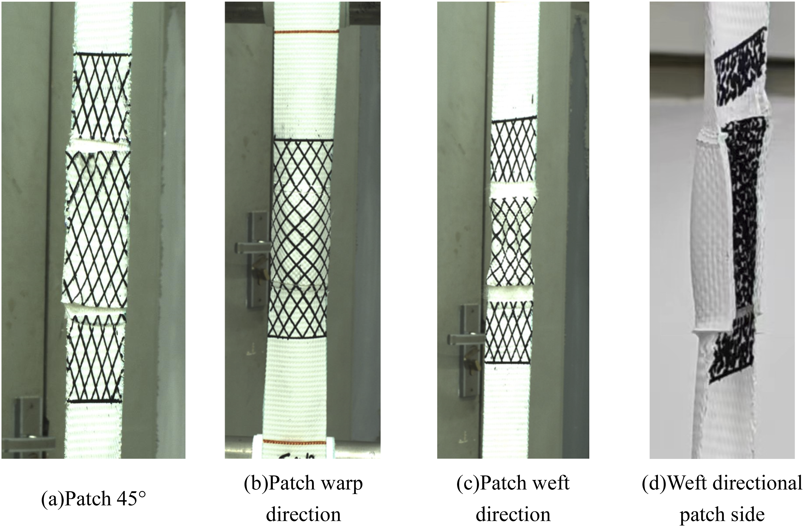
These differing stress forms interact and lead to out-of-plane buckling. In contrast, the specimen exhibits a flat substrate material without out-of-plane buckling when the off-axis angle between the patch and the substrate material is 45° (Figure 12(a)). This is because both the patch and the substrate are subjected to the same pure shear stress and are not affected by the anchorage length. The strength of specimens primarily derives from the bonding between the yarn and the matrix, and its failure mode is similar to that of a lap welded seam.
Stress-strain curves
As shown in Figure 13, the tensile stress-strain relationship curve for the specimen with single-layer patch weld is presented. It can be observed that the off-axis tensile curve of the weld lap welded seam specimen closely resembles that of the pure membrane. Furthermore, as the off-axis angle changes, the off-axis tensile curve exhibits significant variations, highlighting the anisotropic properties of the coated fabric. As the off-axis angle increases, the tensile behavior of the specimen exhibits significant changes. The tensile behavior was classified into three distinct categories based on the stiffness characteristics of the stress-strain curve: warp and weft, small off-axis angles (15°, 75°), and large off-axis angles (30°, 45°, 60°). Noted that the angular-dependent test curves demonstrate distinct separations, confirming the critical influence of off-axis orientation on mechanical response characteristics. For orthogonal off-axis angles, specimens with the weft as the primary direction show lower stiffness compared to those with the warp as the primary direction. This difference arises from the influence of the coated fabric weaving process. When the direction of the weld patch aligns with the substrate material, a significant increase in stress and strain is observed at an off-axis angle of 45°. This is attributed to the alignment of the force directions between the substrate material and the patch, enabling the full utilization of the 45° shear stress. In contrast, weld patch alignment along warp/weft directions produces nearly identical tensile curves. This consistency demonstrates the limited influence of patch orientation on ultimate tensile strength. Stress-strain curves of weld single-cover welded seams with covered patch forms. (a) Base membrane material. (b) The patch direction is the same as the substrate material. (c)Patch warp direction. (d) Patch weft direction.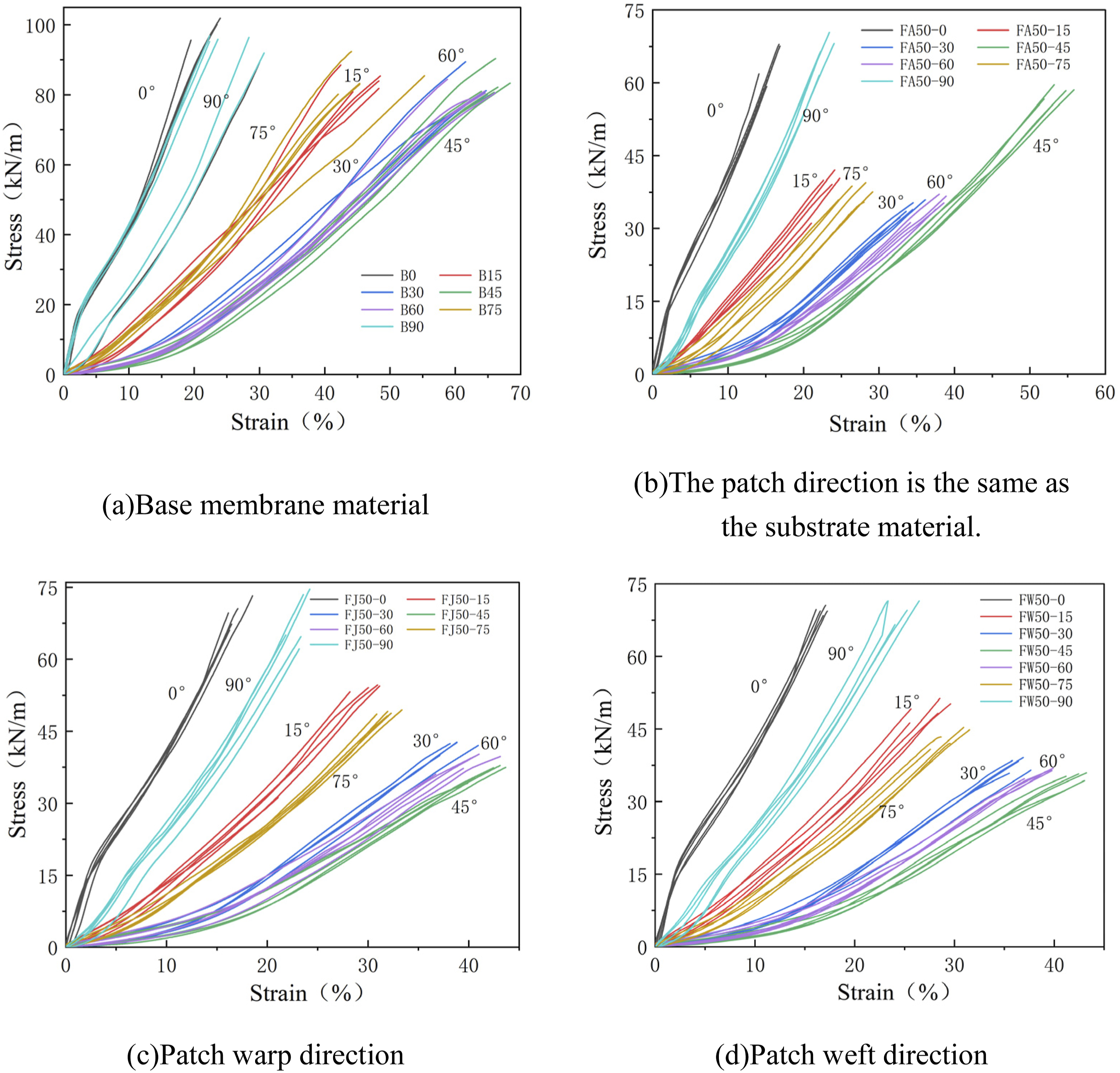
Figure 14 presents the tensile stress-strain relationship curves for the welded coated fabric with double-layer patch. From the perspective of curve trends, there is little difference between the off-axis tensile curves of double-layer and single- layer connections. The off-axis tensile curves vary significantly with changes in angle, highlighting the anisotropic properties of the membrane when considering its off-axis orientation. Stress-strain curves of weld double-cover specimen. (a) Different off-axis angles. (b) Different weld widths.
The off-axis tensile curves of single-layer (Figure 14(c)) and double-layer connections (Figure 14(a)) show similar trends when the patch is aligned in the warp direction. The tensile curves change significantly with off-axis angle, highlighting the anisotropy of coated fabric. Noted that the stress-strain curve of the double-layer connection specimen at 45° off-axis extends further than the single- layer specimen under identical conditions. This suggests the double-layer patch enhances bonding in the central region, improving tensile strength and stiffness.
Figure 14(b) shows stress-strain curves split into warp and weft trends, suggesting minimal impact of weld width on stiffness. However, as the weld width increases, there is a significant change in the stress experienced by the specimen. This behavior was attributed to two factors. Firstly, both the substrate material and the patch are subjected to pure tensile forces, with the coverage connection form having little effect on the specimen’s overall response. Secondly, a larger weld width involves more yarns in force transfer and strengthens adhesion in the central region double-layer patch. As a result, the constraint on the warp tensile behavior of the PVC-coated fabric is enhanced.
Tensile strength and elongation
Tensile strength and elongation at break are fundamental mechanical properties of membrane materials. To characterize the mechanical properties of the specimens, nominal stress and nominal strain are utilized. The expressions for tensile strength and elongation at break are given as follows:
As shown in Figure 15, it is evident that the off-axis angle significantly affects both tensile strength and elongation at break. As the off-axis angle increases, there is a corresponding relationship between the changes in the two curves, which can be roughly classified into two patterns. The first pattern is characterized by a “U”-shaped change in tensile strength and an inverted “U”-shaped change in elongation at break. This behavior primarily occurs when the coated fabric is welded single-layer patch and the angle of the central patch is either warp or weft. In this case, tensile strength initially decreases and then increases as the off-axis angle changes. Noted that the tensile strength at a 45° off-axis angle is marginally lower than at 30° and 60°. Off-axial tensile strength and elongation at break of specimens. (a) Tensile strength. (b) Elongation at break.
The variation in elongation at break exhibits an inverse trend compared to tensile strength, initially increasing and then decreasing with changes in the off-axis angle. This behavior is primarily attributed to the stress distribution within the membrane material. At larger off-axis angles, tensile-shear coupling in the substrate materials causes yarn deflection toward the tensile direction of specimen, driving overall test piece deviation. In contrast, the middle patch, subjected to pure tensile stress in the warp and weft directions, aligns with the tensile direction of the test specimen and does not deflect. Consequently, fine fibers between the substrate material and the patch are displaced, reducing the bonding strength at the interface between the patch and the substrate material. In single-layer warp/weft patch comparisons, the tensile strength of warp direction notably exceeds that of the weft. However, the elongation at break curves are largely consistent for both directions, indicating that single-layer connections in the warp direction provide superior performance.
As the off-axis angle increases, the tensile strength exhibits a distinct “W”-shaped variation, while the elongation at break follows an inverted “V”-shaped trend. Based on the local peak observed at an off-axis angle of 45°, two distinct categories were identified. PVC-coated fabric welded with single-layer patch amplify the 45° local strain peak. At this angle, the tensile strength shows a significant increase, reaching approximately 69.71% of the tensile strength of the pure coated fabric material. Compared to other single-layer connections, the tensile strength increases by 25.94% for the patch in the warp direction and by 28.35% for the patch in the weft direction. Patch and substrate material at 45° create a stable diagonal fiber network, reducing traditional orthogonal anisotropy. This specific fiber architecture enables multidirectional load transfer, facilitating stress redistribution across the interface. From the perspective of micromechanics, 45° fibers engage tensile and shear mechanisms, creating a biaxial stress field at joints instead of pure shear. This optimized stress distribution lowers local concentrations, boosting load capacity and joint deformation compatibility. Moreover, the coordinated stress mode of F50-45 specimens optimizes yarn tilt-to-vertical alignment distance in patch and substrate. Consequently, the elongation at break at this angle increases significantly compared to other angles, reaching approximately 81.2% of that of the pure coated fabric specimen.
Coated fabric welds with double-layer warp-aligned patches show a “W”-shaped tensile strength curve and an inverted “V” elongation-at-break trend as off-axis angles increase. The local peak at the 45° angle is relatively small and symmetrically distributed around the 45° direction. Tensile curves of double-layer specimens match pure material, reflecting enhanced membrane-to-membrane bonding at weld seams via dual-layer configuration.
As shown in Figure 15(a), the tensile strength curve of the double-coverage connection is compared with that of the single-coverage connection under the same conditions. The unexpectedly low strength observed in the butt-welding with double tape at both 0° and 90° directions is mainly attributed to unfavorable stress superposition effects inherent to this joint configuration under orthogonal loading. The double-layer patch imposes dual constraints, restricting the welded region and hindering molten PVC flow, causing inadequate fusion. Second, during loading, the double-layer connection induces a self-balancing internal stress field in orthogonal directions. The opposing forces of the upper and lower cover patches lead to an uneven stress distribution in the weld area, impairing load transfer efficiency. Finally, compared with the butt-welding with single tape, the butt-welding with double tape exhibits a more pronounced stiffness discontinuity in the orthogonal directions. This stiffness mismatch causes stress concentration, making the joint more prone to failure under relatively lower loads.
Based on the statistical data, calculations for strength reduction and elongation reduction were performed. The relationship curves between tensile strength and elongation at break with respect to the off-axis angle under different patching modes are presented in Figure 16. The numbers represent the weld width, with values of 50 mm and 70 mm, respectively. Additionally, Figure 17 illustrates the relationship curves of tensile strength and elongation at break with the off-axis angle for double-layer specimens at different weld widths. Relationship between off-axial tensile strength, elongation and covering patch forms of specimens. (a) Tensile strength, (b) Elongation at break. Relationship between off-axial tensile strength, elongation at break and covering weld width of specimens (Double coverage connection). (a) Tensile strength. (b) Elongation at break.

Figure 16(a) shows that at varying off-axis angles, coverage methods’ impact on coated fabric tensile strength differentiates into three distinct groups. The first category includes the warp and weft specimens. The tensile strength of the specimen is relatively low when a single-layer connection is applied. In this case, the cover patch and the substrate material are aligned with the warp or weft directions, with the pure tensile force being applied synergistically. This configuration allows for better utilization of the yarn’s tensile properties. As shown in Figure 17(a), as the weld width increases, the tensile strength of the double-layer specimen also increases, demonstrating the positive effect of the weld width. Furthermore, when comparing specimens with single and double coverage under identical conditions (i.e., ‘FJ50’ and ‘SJ50’), the tensile strength of the single-cover specimen is greater than that of the double-covered one. This is because double coverage requires more thermal connection points, which weakens the tensile strength of the specimen. The maximum tensile strength, 72.15 kN/m, occurs at a weld width of 70 mm.
The second category involves cases where the off-axis angle of the substrate materials is 45°. In this case, the tensile strength is maximized when the patch is also oriented at 45°, approximately 1.6 times greater than that of patches oriented in the warp and weft directions. Under identical conditions, double-layer coverage (e.g., FJ50, SJ50) exhibits 22.53% greater tensile strength than single-layer connections, demonstrating enhanced inter-coat bonding through added constraints from double-layer patches under shear. However, the most effective configuration remains when the coated fabric and patch are subjected to pure shear force, as seen in the FA50 specimen. The third category encompasses other off-axis angle cases, including specimens with 15°, 30°, 60°, and 75° off-axis angles. In these cases, the tensile strength of patches in the warp and weft directions exceeds that of patches at the off-axis angles. Specimens experience tensile-shear coupling stresses, resulting in a complex stress distribution. The middle covering patch plays a key role in the connection during the stress process of coated fabric. Patch alignment with warp/weft directions amplifies tensile forces, enhancing specimen stiffness and strength.
As shown in Figures 16(b) and 17(b), the elongation at break under different coverage modes is presented. The effect of coverage mode on the tensile strength of the coated fabric varies with different off-axis angles. The classification method follows the same structure as for tensile strength and can be divided into three categories based on the off-axis angle. The first category includes the warp and weft specimens. Compared to the other types, the elongation at break under different patch types shows minimal variation. The minimum value is 12.41%, and the maximum value is 24.49%, which occur for the ‘SJ30’ and ‘FW50’ specimens, respectively. The second category involves specimens with a 45° off-axis angle. Single-layer specimens with aligned patches show maximum elongation at break, followed by warp-aligned double-layer patches. The smallest elongation at break is observed in the single-layer patch aligned with the warp and weft directions. Combined with the tensile strength analysis in Figure 17, it is clear that the specimen subjected to pure shear force with a 45° patch provides the best performance. The third category includes specimens with other off-axis angles, including 15°, 30°, 60°, and 75°. For specimens with smaller off-axis angles, the variation trend is similar to that of the warp and weft specimens, with more yarns subjected to tensile force. Increased off-axis angles align specimen trends with pure membranes, dominated by yarn shear and coating adhesion effects.
In summary, it is essential to account for the strength reduction at the welding point when designing the membrane structure node with weld coverage treatment. For warp and weft coated fabrics, the optimal connection form is double-layer patch aligned in the warp direction and a coverage width greater than 70 mm. Under these conditions, the tensile strength of the weld is 0.7 times that of the substrate material. For off-axis coated fabric with a 45° substrate material deflection angle and a patch direction of 45°, and a coverage width greater than 50 mm, the tensile strength of the weld is 0.65 times that of the substrate material. Furthermore, the anchorage length of the substrate material in the cover connection is smaller than that of the lap welded seam specimen for the same weld width. Therefore, when designing a welded cover connection, the constraining force of the connector should be carefully considered, and the weld width should be appropriately increased to ensure optimal performance.
Strain field analysis
The strain field distribution of the coated fabric with single-layer patch during the tensile process was obtained by calculation, as shown in Figures 18 and 19. The longitudinal strain field of the coated fabric with patch varies systematically with the off-axis angle when aligned with that of the parent material. Horizontal high-strain zones are localized at the upper and lower edges of the central weld, corresponding to patch-to-base contact areas, while the secondary strain zone observed in the mid-section aligns with base-to-base contact regions. At small and large off-axis angles, the high-strain regions in the coated fabric no longer remain horizontal but show a distinct tilt. The larger the off-axis angle is, the more obvious the inclination is. This occurs because the substrate material and patch experience equal tensile-shear coupling, with an angular misalignment between yarn stress direction and specimen tensile direction. Yarn deflect toward the longitudinal tensile direction, driving overall specimen deflection and high-strain zone tilting due to yarn-coating bonding. When the off-axis angle of the patch membrane changes with the warp and weft, the longitudinal strain field changes with the off-axis angle, and there is a horizontal high strain zone at the upper and lower edges of the central weld area. Patch alignment with warp/weft limits membrane deflection as fibers bear longitudinal tensile stress in the same direction.
For transverse strain, negative strain is presented at different off-axis angles. The single-layer connection specimen generates negative strain under varying off-axis angles when the patch aligns with warp/weft directions. Continuous stretching amplifies stiffness mutation effects, spreading central negative strain zones outward or creating concave central regions. At this time, the substrate material and the patch are in a complex stress state. Continuous tension-shear coupling deflects substrate material fibers toward the tensile direction, subjecting the patch to normal stress. Under the combination of the two, the specimen produces obvious deformation in the central area.
Increased off-axis angle reveals a clearer regularity in shear strain for warp-aligned weld single-layer connections. The shear strain field is symmetrically distributed in the off-axis direction. This shows that when the patch is in the warp direction, it is beneficial to the coordinated force of the coated fabric and the reasonable distribution of the strain. The two-dimensional strain field of single-cover specimen in warp direction. (a)0°, (b)45°, (c)90°. The two-dimensional strain field of single-cover specimen in weft direction. (a) 0°, (b) 45°, (c) 90°.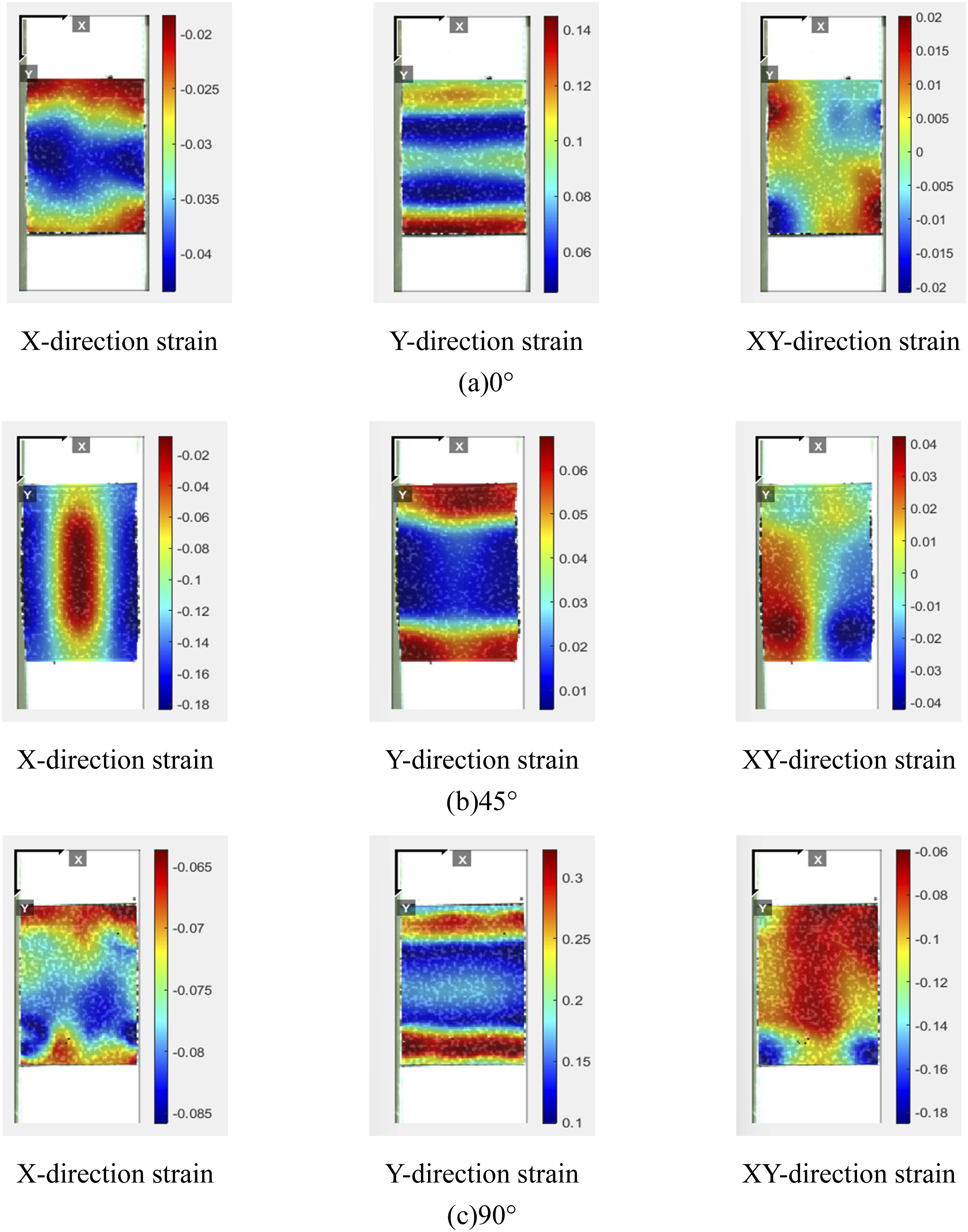

For the strain field distribution of the double-layer specimen during the tensile process, the longitudinal strain is observed, as shown in Figure 20. The variation law of the longitudinal strain field of the double-layer connection at different off-axis angles is similar to that of the single- layer connection. There is a horizontal high strain zone at the upper and lower edges of the central weld area. This is because the synergy between the patch and the substrate material in the middle double-layer weld area mainly depends on the bonding force between the coating and the yarn. Increased tensile force causes specimen elongation, with middle patch constraints failing, leading to high edge strain. For the transverse strain, the form of the double-layer weld further widens the stiffness gap between the substrate material and the patch. The discontinuous transmission of the strain induces a shrinkage effect, manifesting as a central concave region with negative strain in the strain field. Shear strain varies significantly with off-axis angle, exhibiting a central symmetry in the strain field around the off-axis direction as its axis. The two-dimensional strain field of weld double-cover specimens.
Conclusions
In this paper, uniaxial tensile tests were conducted on 250T PVC-coated fabric with multiple-layer welded seam. The effects of the off-axis angle, weld width and patch configuration on the tensile strength, elongation at break, and failure mode of the PVC-coated fabric welded seam connections were analyzed. The strain field distribution on the coated fabric surface during the tensile process was captured using DIC technology. The main conclusions are as follows: 1. Weld-covered PVC-coated fabrics show divergent tensile strength and elongation responses to off-axis angles. For coated fabric welds with single-layer warp /weft patch, tensile strength and elongation at break follow a ‘U’ and inverted ‘U’ pattern as the off-axis angle increases. For single-layer patch with an intermediate off axis angle aligned with the substrate material, the trend shifts to a ‘W’ and inverted ‘V’ pattern. 2. The specimen with patch connection exhibits significant transverse shrinkage strain in the central area. In the longitudinal strain direction, there are high strain zones at the upper and lower edges of the center area of the weld seam that are aligned with the inclination direction of the off-axis angle. When the patch is the warp direction, it is beneficial for the coordinated force distribution of the coated fabric and the reasonable distribution of the strain field. 3. In designing the membrane joint with weld coverage, the strength reduction at the weld must be accounted for. For warp and weft substrate material with a double-layer patch, the patch width should exceed 70 mm, then take the tensile strength of the weld for 0.7 times the tensile strength of the substrate material calculation. For off-axis coated fabric, when both the substrate and patch are oriented at a 45° off-axis angle and the patch width exceeds 50 mm, the tensile strength of the substrate is 0.65 times that of the weld seam. 4. Under identical weld widths, the substrate metal anchorage length in cover-patch connections is shorter than that in lap splice specimens. When designing connections with weld coverage, it is necessary to fully consider the constraint force of the connecting components and appropriately widen the design weld width.
Footnotes
Funding
The author(s) disclosed receipt of the following financial support for the research, authorship, and/or publication of this article: This work was supported by the National Natural Science Foundation of China; No. 52308222, 52278229. China Postdoctoral Science Foundation; No. 2023M733775.
Declaration of conflicting interests
The author(s) declared no potential conflicts of interest with respect to the research, authorship, and/or publication of this article.