
Abstract
The mechanical performance degradation of welded seams under cyclic loading may lead to the failure of membrane structures. To investigate the influence of the off-axis angle and the the welded width on mechanical performance, the elastic modulus, ratcheting strain, residual strain and strain energy were studied based on the uniaxial cyclic tensile tests of welded seams. The results show that the elastic modulus of the welded seam specimens shows obvious anisotropy under cyclic loading, and the welded width has the greatest influence on the elastic modulus of the welded seam specimens with 15° and 75° off-axis angles, under which off-axis angle the welded seam specimens have good recoverability. The irreversible plastic strain of the axial welded seam specimens is close to that of the membrane specimen. The plastic development of the specimen is obvious under large off-axis angles (30°, 45°, 60°), and the final residual displacement of the welded seam specimens reach 3%–4%.
Introduction
Membrane structures have irreplaceable advantages such as strong architectural expression and large application space, 1 which are widely used in stadiums, storage structures and other buildings. 2 The structure enhances the overall stiffness by adding pre-tension to resist external loads. As a commonly used material for membrane structures, coated fabric membrane mainly consists of fiber-based fabric and coating. The warp and weft fiber bundles form the fiber-based fabrics according to weaving method. Among them, PVC coated fabric membrane has significant advantages in material strength and price. 3 The mechanical properties of coated fabric membrane have been extensively studied, including uniaxial tensile performance, 4 biaxial tensile performance,5,6 shear performance, 7 tearing performance8,9 and kinetic performance,10,11 etc. The corresponding intrinsic model was proposed to characterize the complex mechanical behavior of coated fabric membrane.12,13 The complex weaving process and mechanical behavior of membrane material make it show significant nonlinearity. 14
Due to the limited width of membrane material affected by the production process, it is usually necessary to cut and splice membrane material into membrane surfaces to form an overall structure,
15
as shown in Figure 1. The connection methods for membrane materials primarily include welded seam connections and pressing plate connections. The pressing plate connection is mainly utilized for securing the edges, while the welded seam connection minimally affects the aesthetic appearance of the structure, making it the preferred choice for splicing the central areas of the membrane surface. Welded seams are achieved by applying high-frequency and high-temperature heating to the polymer on the surface of the membranes.
16
The welded joint specimens achieve load transfer between the membrane materials through a coating connection, and their performance is a key factor affecting the overall safety performance of the structure.
17
The tensile strength of the welded seams decreased firstly and then increased with the expansion of the weld length. The failure of welded seams mainly occurred in the base material, which was manifested as diagonal tensile failure caused by stress concentration near the clamping section and strength reduction failure at the welding edge.18,19 Wang investigated the reasonable weld width and ultimate tensile stress of welded joints.
20
Xue compared the weld strength of coated fabrics at ambient and elevated temperatures.
21
The welding processes were also considered to have an impact on the connection performance.22–24 The width design of the weld seam should comprehensively consider the material characteristics and actual stress. Therefore, the design regulation recommends that the welded width of PTFE, PVC, and ETFE membrane should not be less than 50 mm, 25 mm, and 10 mm, respectively.25,26 Typical tensioned membrane structure and connection diagrams.
The membrane structures are directly exposed to the external environment in its engineering application, subjected to long-term cyclic loading such as gusts of wind, rain, snow, hail, and thermal expansion and contraction triggered by temperature changes, 26 which leads to residual deformation of the membrane surface and reduces the prestress on the membrane surface. To clarify the mechanical properties of membrane under cyclic loads, Hu established the relational equations of cyclic elastic modulus, ratcheting strain and hysteresis loop area with the number of cycles on ETFE membrane. 27 Charbonneau studied the influences of cyclic stress amplitude. 28 The tensile performance of membrane under cyclic loads are mainly related to the number of cycles, stress amplitude and the weaving structure of the substrate.29–31 The current research mainly focused on the mechanical properties of membrane under cyclic loading, while ignoring the performance of welded seams that are more susceptible to damage under cyclic load.
Cyclic tensile tests were carried out on coated fabric membrane and the welded seams in this paper. The change rule of stress-strain curve, elastic modulus, ratcheting strain, residual strain and strain energy was analyzed considering the number of cycles. Besides, the deformation characteristics and energy dissipation law of welded seams were studied. This paper provides references for the design of welded seams in membrane structures.
Test specimens and setup
Test specimens
Material parameters.

The specimens for tensile tests are strip-shaped with a length of 300 mm, in which the clamping sections at both ends are 50 mm in length.25,26 The widths of specimens are 30 mm, 50 mm, and 70 mm respectively. Seven off-axis (warp) angle variations of 0°, 15°, 30°, 45°, 60°, 75°, and 90° were considered and the off-axis specimens were cut as shown in Figure 2(a). Test specimens.
For the welded seam specimen, first of all, the whole piece of diaphragm high-frequency welded bonding heat bonding, and then cut to get the test specimen. The membrane high-frequency welding of the film material uses a frequency of 25 MHz for at least 5 s to meet the standard.25,26 Three identical specimens were prepared for testing. The detailed parameters of the welded seam specimen were shown in Figure 2(b).
Test setup
The cyclic tensile test was conducted using a triangular waveform reciprocating load, as illustrated in Figure 3. The loading rate was set at 30 N/s, and the number of loading cycles was 10. The stress range varied between 3 kN/m and 16 kN/m, where 3 kN/m represents the permanent prestress value of the membrane structure (approximately 1/25 of the uniaxial strength), and 16 kN/m corresponds to the commonly used design strength (approximately 1/5 of the uniaxial strength). A high-precision tensile transducer and a large deformation displacement meter were employed to measure the tensile force and strain values. Each specimen with identical parameters was tested three times to ensure reliability. The test setup is depicted in Figure 3. Test setup and loading scheme.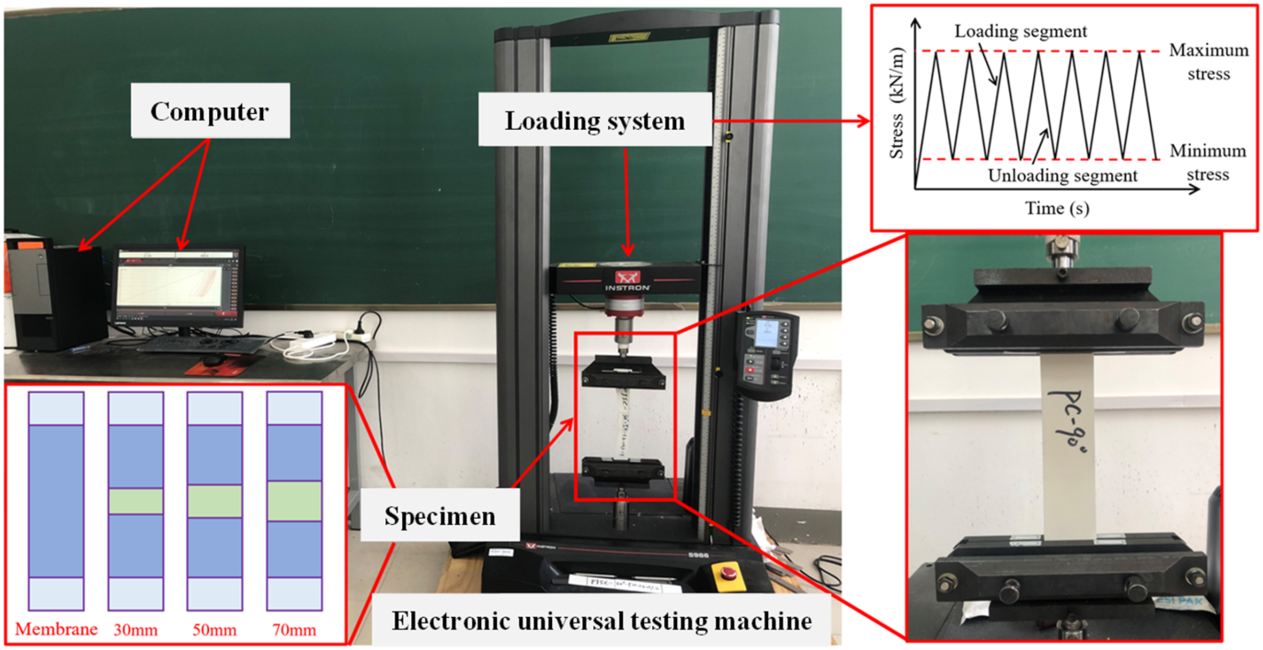
Results and discussions
Stress-strain curve
The stress-strain curves of membrane and welded seam specimens under cyclic tensile loading at different off-axis angles are shown in Figure 4. At different off-axis angles, the loading and unloading curves of the specimens show significant differences. The cyclic tensile curves of the samples at 0° and 90°, 15° and 75°, and 30° and 60° are relatively similar. However, there are significant differences in performance between PVC-coated fabrics in the warp and weft directions. Additionally, the degrees of crimp exchange between the fabric substrates and the warp and weft directions vary. As a result, distinctions are observed among the samples. In the cyclic tensile process, specimens at 0° and 90° are primarily supported by warp and weft yarns, respectively. These specimens demonstrate strong tensile stiffness with minimal residual displacement. To the 45° off-axis test specimens, one or both ends of the yarn are not constrained by the fixture. The yarn is subjected to tensile and shear stresses, resulting in a band-like distribution of longitudinal strain fields with an off-axis angle. This leads to lower tensile stiffness and higher residual deformation for the specimen. With the number of cycles increasing, the residual deformation gradually increases and the stress-strain curve becomes more linear. Stress-strain curves under off-axis cyclic tensile tests. (a) membrane, (b) 30 mm welded seams, (c) 50 mm welded seams, (d) 70 mm welded seams.
During cyclic loading at the same off-axis angle, compared to membrane specimens, the tensile stiffness of welded seam specimens increased and their residual displacement decreased. This was more pronounced as the width of the welded seam increased. This is due to the fact that the welded area in the middle of the specimen plays a certain restraining role on its tensile deformation, which increases the bridging effect between warp and weft yarns to some extent.
To compare the curve changes more intuitively during each cyclic loading stage, the starting points of 10 loading curves were placed at the coordinate origin to obtain stress-strain curves for different loading section cross sections, as shown in Figure 5. The difference between the first loaded curve and subsequent loaded curves is significant, especially from 0° (90°) to 45° deflection angle. As the number of cycles increases, the difference in subsequent cyclic tensile loading curves decreases and tends to be linearized. This is mainly because the tensile strength of specimens with different deflection angles varies greatly. Under equal stress amplitude loading conditions, the 45° deflection angle specimen undergoes significant plastic deformation, while the 0° (90°) specimen experiences less plastic deformation. In addition, the large deformation of the 45° specimen due to shear stress results in the largest difference between the first cycle loading curve and subsequent loading curves for the 45° specimen. During the subsequent cyclic loading process, the fibers of the specimen are repeatedly stretched and straightened, leading to a gradual saturation of internal damage, making the subsequent loading curves with an improved degree of linearity. Loading curves of TX30-III under 10 cycles of different off-axis angles. (a) 0°, (b) 15°, (c) 30°, (d) 45°, e) 60°, (f) 75°, (g) 90°.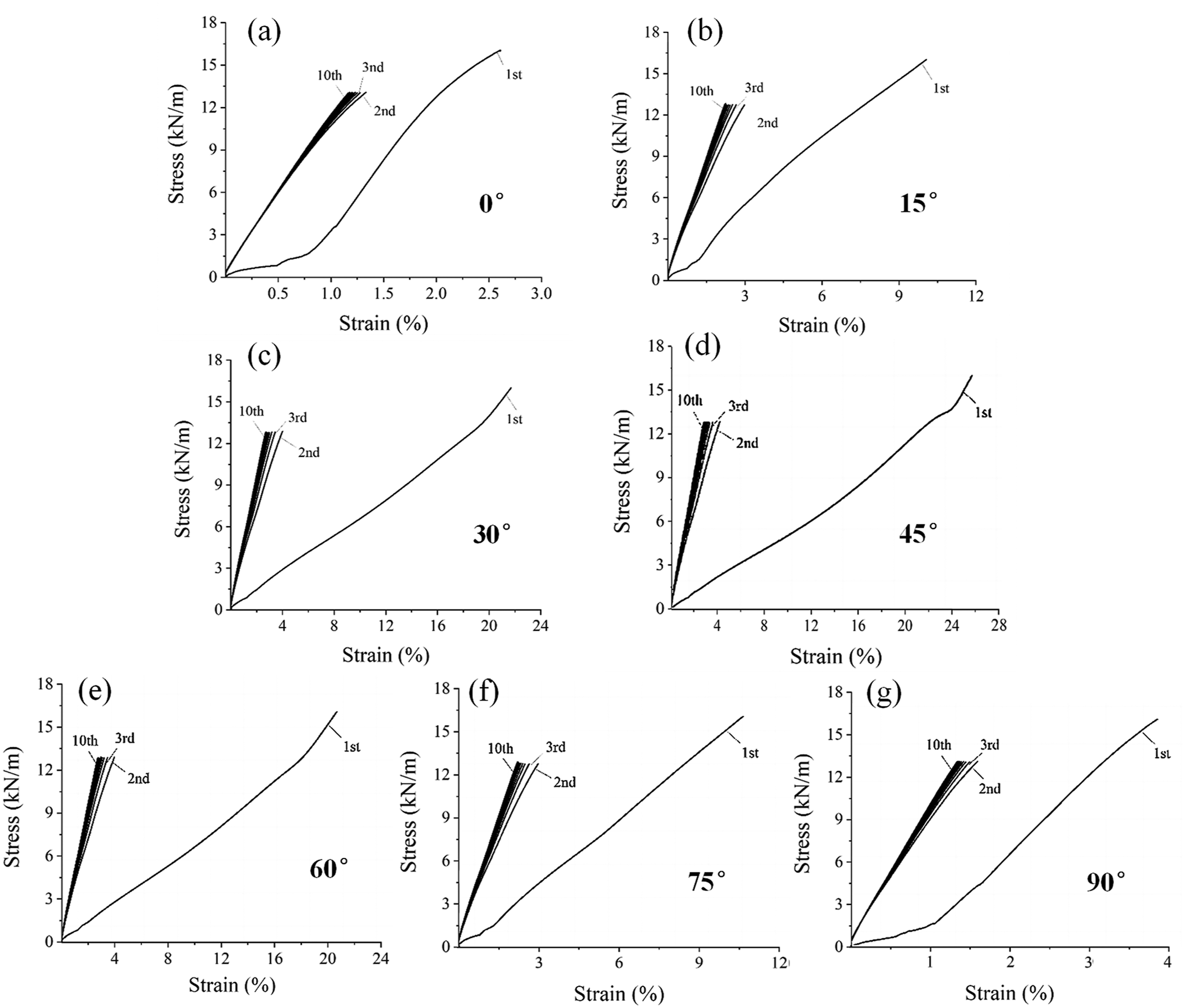
Elastic modulus
The tensile curves of the membrane material and welded seams exhibit pronounced nonlinear characteristics. To accurately determine the elastic modulus for each cycle of the tensile curve, the loading and unloading curves are segmented into 10 sections, and the corresponding elastic modulus is calculated by averaging the values of each segment. The phased elastic modulus algorithm is used to determine the linearization segmentation point. The segmented linear elastic modulus is obtained by using the least-squares method of fitting. The calculation method is shown in Figure 6. Calculation method of loading and unloading.


Elastic modulus under the first and last loading.

Due to the angle between the yarn and the direction of force in off-axis specimens, the initial elastic modulus of the specimen shows significant anisotropy under the combined action of tension and shear. The initial elastic modulus at 0° (warp) is approximately 10 times that at 45°, while the 45° direction experiences minimal cyclic shear stress, resulting in a minimum initial elastic modulus. Compared to the membrane specimens, the elastic modulus of the welded seam specimen under loading increases significantly with increasing welded width. This is mainly due to an increase in local stiffness caused by a larger effective thickness in the welded part. Taking the 90° direction (weft) test piece as an example, the first loading elastic modulus of the 30 mm, 50 mm and 70 mm welded seam specimens increased by 7.5%, 10.3% and 13.7% respectively. The influence of the same welded width on the elastic modulus of specimens under initial loading in both the 0° direction (warp) and the 90° direction (weft) is more pronounced for off-axis specimens compared to on-axis specimens. Since the first loading eliminates most of the nonlinear behavior of the material, the elastic modulus for subsequent loading is much larger than that for the first loading under the same working condition.
The last loading elastic modulus shows that with the increase of welded width, the improvement rate of the last loading elastic modulus increases compared to the membrane specimen. The specimen with the weld seam of 70 mm and an off-axis angle of 15° has improved 31.2%. Compared with the warp specimens, the elastic modulus of the latitudinal weld joint specimen under the same welding width increases more significantly after the last loading than that before. The elastic modulus of the latitudinal test piece with the welded width of 70 mm increased by 12.1% compared to the membrane specimen after the last loading. The last elastic modulus of the 15° off-axis angle specimen and the 75° off-axis angle specimen showed the most significant change compared to the membrane specimens. As the number of cycles increased, the increase in loading elastic modulus decreased by more than 60%. The welding width has a small impact on the off-axis angle of specimens at 30°, 45°, and 60°. The deviation from the last loaded elastic modulus of the membrane specimen remains within 5%.
Ratcheting strain
Ratcheting strain is the progressive accumulation of plastic deformation produced by the material in the ratcheting effect. Excessive accumulation of ratcheting strain will affect the normal use of the structure or member, and the membrane structure will have problems such as stress relaxation and bagging effect. The ratcheting strain 
The ratcheting strain of membrane and welded seam specimens at different off-axis angles are shown in Figure 7. For ratchet strain, the coefficient of variation ranged from 1.31% to 4.18%, with the maximum coefficient occurring at an off-axis angle of 60°. Due to the continuous accumulation of plastic deformation during cyclic loading, the rate of growth in cyclic plastic strain decreases significantly with increasing membrane tensile hardening. This results in a gradual decrease in ratcheting strain growth rates at different off-axis angles as the number of cycles increases. Affected by the distribution of yarns and stress state, the ratcheting strain of the specimens showed significant anisotropy. The cyclic plastic strains of different off-axis specimens varied greatly, with smaller ratcheting strains for 0° and 90° off-axis specimens and a maximum ratcheting strain for the 45° off-axis specimens. The membrane specimens reached 27% after completion of cyclic loading. Compared to the membrane specimens, the ratcheting strain of welded seam specimens at 0° and 90° off-axis angles is less affected by the welded width. Under other off-axis angles, with the increase in the width of the welded seams, there is a certain degree of decrease in ratcheting strain under each loading cycle. Compared to the membrane specimen, the ratcheting strain of the 70 mm welded seam specimens at angles of 15°, 30°, and 45° decreased by 5.7%, 22.7%, and 44.0%, respectively. Ratcheting strain at different off-axis angles.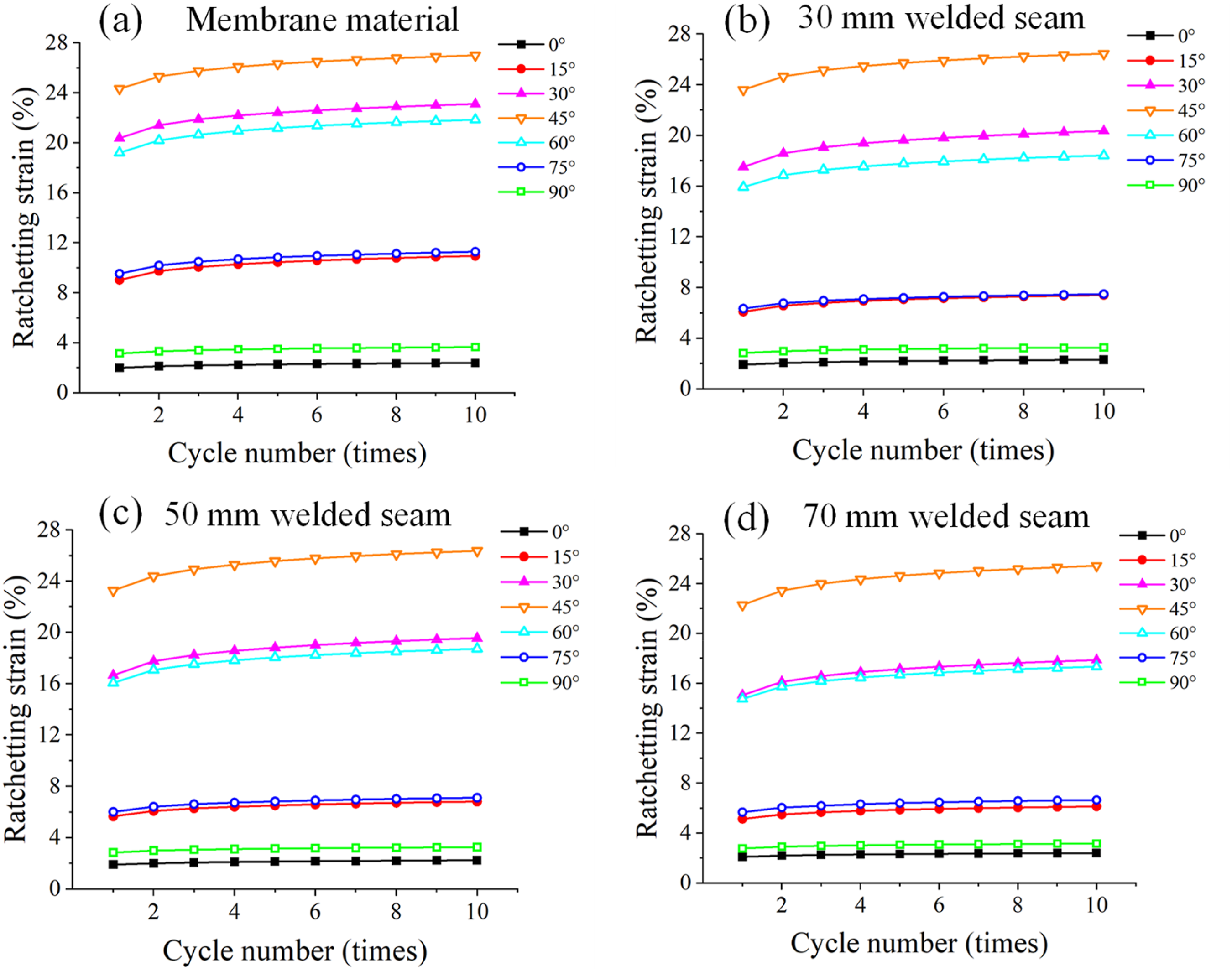
Residual strain
Membrane materials exhibit significant viscoelastic characteristics, mainly including immediately recoverable elastic deformation, slowly recoverable viscous deformation over time, and irreversible plastic deformation. Among these, plastic deformation has a significant impact on the cutting design and long-term use of membrane structures. The viscous and plastic deformation characteristics of the samples were investigated by monitoring dimensional changes over a period of 150 days following unloading. During this period, data collection was conducted 12 times, with intervals gradually increasing. Five measurements were taken within the first hour, and a total of seven measurements were completed on the first day,2,32 as shown in Figure 8. The coefficient of variation for residual strain ranged from 1.93% to 6.85%. The 45° specimens demonstrated a consistently higher coefficient of variation across all time stages, which notably decreased as time progressed.
33
Residual strain versus time curve. (a)–(d) The influence of welded width. (e)–(k) The influence of off-axis angle.
Overall, the residual strain of specimens decreases logarithmically with time. The viscous deformation reaching 90% of the total deformation within 3 days after unloading. In both warp and weft specimens, the final residual strain of membrane specimens and welded joint specimens is generally small, remaining within 0.25%, with the residual stress of weft specimens being relatively larger than that of warp specimens. For off-axis specimens, the 45° specimen has the highest level of residual strain throughout the entire process, with a final residual displacement level of 3% to 4%. As the welded width increases, the residual strain of the specimens tends to decrease. The residual stress level is relatively small compared to the membrane specimen. This is mainly due to the lower stress level of the membrane yarn at the welded seam, which is dominated by elastic deformation, resulting in a decrease in the overall residual strain.
Due to the stabilization of residual deformation after 150 days, the final residual strain after unloading for 150 days is considered as plastic strain. The strain of specimens is decomposed into three parts: elastic strain, recovers viscous strain, and irreversible plastic strain, in which the largest proportion is elastic strain, as is shown in Figure 9. In membrane specimens and welded joint specimens, the final residual displacement of off-axis specimens is greater than that of axial specimens. This phenomenon is most pronounced at 15° and 75° offset angles. At the same off-axis angle, compared to the membrane specimen, the elastic strain ratio of the welded seam specimen decreases with increasing welded width, and the elastic strain ratio is between 40% and 60%. The proportion of irreversible plastic strain in the off-axis specimens increases with width. The irreversible plastic strain in the axial specimens is generally low, not exceeding 18%. Strain decomposition of specimens.
Energy consumption
The hysteresis curve is an important basis for evaluating the energy dissipation and stiffness degradation of the material, in which the area of the hysteresis loop Schematic diagram of hysteresis loop area calculation.

The relationships between the hysteresis loop area and the cycle times of specimens are shown in Figure 11. The hysteresis loop area generated by cyclic stretching of specimens is negatively correlated with the number of cycles and the hysteresis loop area decreases the most from the first cycle to the second cycle. The plastic strain energy decreases gradually with the increase of the number of cycles and finally stabilizes. The plastic strain energy decreases gradually with the increase of the number of cycles and finally tends to stabilize. For the specimens with longitudinal and latitudinal welded seams, their energy dissipation characteristics are relatively close to those of the membrane specimens. For the specimens with off-axis weld seams, the energy dissipation capacity of the specimens decreases with the increase of the welded width during the first three cycles of cyclic loading. However, after the third cycle loading, the energy dissipation capacity of specimens with different welded widths becomes approximately the same. Hysteresis loop area and the distribution.
In order to further clarify the energy dissipation law of the specimen under cyclic loading, the total strain energy 


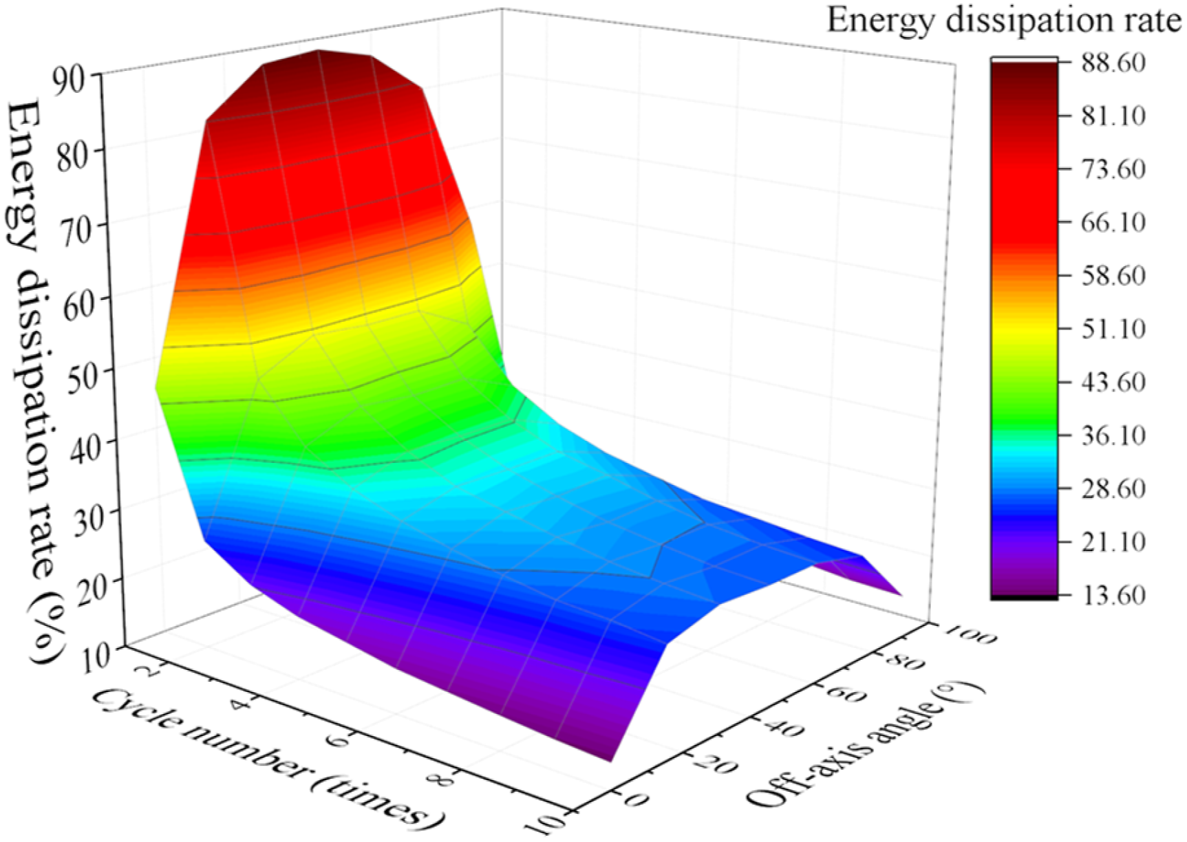
The total strain energy, plastic strain energy, and elastic strain energy of the specimens are shown in Figure 12. The plastic strain energy decreases sharply after the first three cyclic loadings and then remains relatively stable. The elastic strain changes slightly with the loading cycles. Therefore, the change in total energy is mainly related to the plastic strain, which is mainly due to the presence of tension gaps in the manufacturing process of the membrane fiber bundles, specimen loading process fiber slippage, and material functional interlayer peeling. A three-dimensional distribution surface of cycle number-off-axis angle-energy dissipation rate for membrane specimens is shown in Figure 13. It can be intuitively observed that the specimen exhibits the highest energy dissipation rate during the first cycle, showing significant nonlinearity. Subsequently, there is a large energy dissipation feature in the 45° direction, and the material’s energy dissipation rate is symmetrically distributed about the 45° off-axis direction. Total strain energy, plastic strain energy, elastic strain energy under different cycle times. The distribution of energy dissipation rates under different cycle numbers and off-axis angles.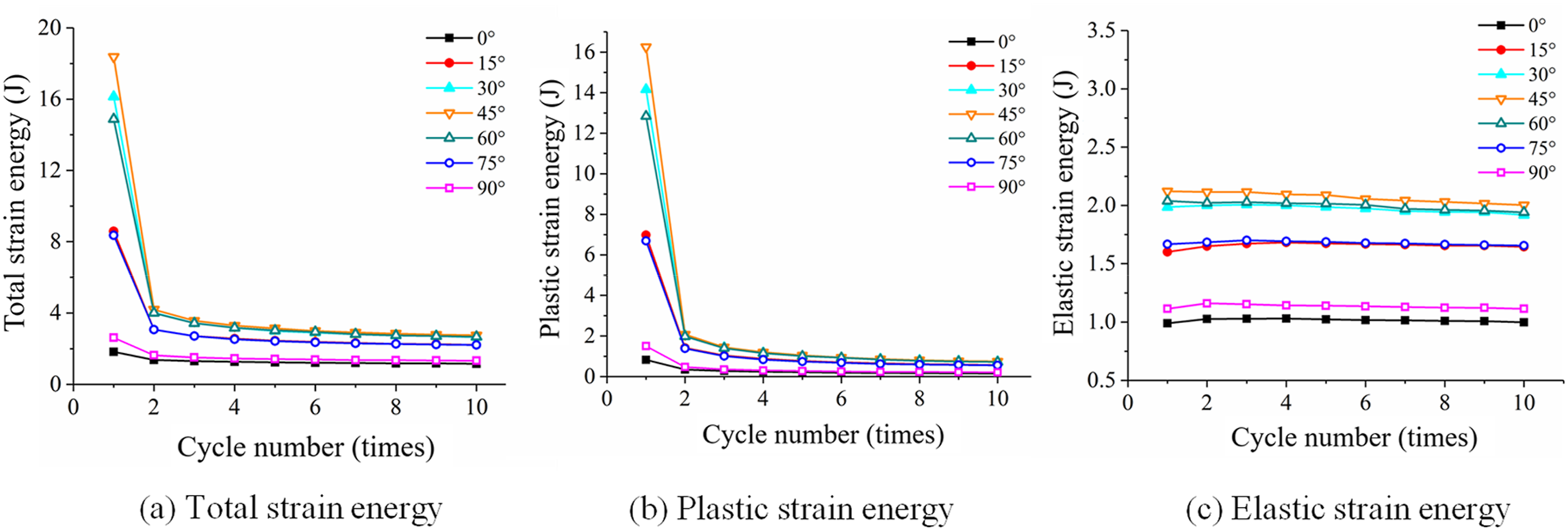
The ratios of elastic strain energy and plastic strain energy to total strain energy are defined as the strain energy recovery rate WiE and energy dissipation rate W
iP
, respectively. The relationship curves between WiE and W
iP
and off-axis angles at the end of the last cycle for specimens with different welded widths are shown in Figure 14. As the welded width increases, the variation in strain energy recovery rate and energy dissipation rate among specimens with different off-axis angles tends to be uniform. The WiE and WiP of the membrane specimens in the warp and weft directions are much larger than those in other off-axis directions (15°, 30°, 45°, 60°, 75°), while the WiE and W
iP
in these five off-axis directions are relatively close. As the welded width of the specimens increases, the differences in WiE and W
iP
in these five off-axis directions gradually increase. This may be due to the higher local tensile stiffness of the welded seam specimens, which exacerbates the influence of off-axis angles on the tensile results. That is, in the case of small off-axis angles (15° and 75°), due to the higher tensile strength of the specimens, there is less plastic damage at the welded seam, and the welded seam specimens exhibit better recovery capabilities. However, in the case of large off-axis angles (30°, 45°, 60°), due to the lower tensile strength of the specimens, plastic damage such as debonding and coating delamination occurs in the overlap area, resulting in a higher energy dissipation rate for specimens with larger overlap widths. Strain energy recovery rate and energy distribution rate under different off-axis angles.
Conclusions
Based on the uniaxial cyclic tensile tests of the membrane and the welded seam specimens, the influence of different welding widths, off-axis angles, and cycle numbers on the viscous behavior and energy dissipation of the specimens was studied. The main conclusions are as follows: (1) The elastic modulus of both the membrane and weld seam specimens exhibits significant anisotropy. The presence of the welded seam increases the local stiffness of the specimen, resulting in a marked increase in both the initial and final loading elastic modulus as the welded width increases. Notably, the elastic modulus of specimens with off-axis angles of 15° and 75° shows the most pronounced variation compared to the membrane specimens. As the number of loading cycles increases, the rate of increase in the loading elastic modulus diminishes by over 60%. The welded width has a minimal effect on the specimens with off-axis angles of 30°, 45°, and 60°, with deviations from the final loading elastic modulus of the membrane specimens remaining within 5%. (2) The increase in ratcheting strain for both the membrane and welded seam specimens demonstrates a negative power function relationship with the number of cycles. The residual strain of the specimens decreases logarithmically over time, with viscoelastic deformation diminishing by 90% within 3 days following unloading. The irreversible plastic strain for the warp and weft specimens is minimal, both remaining below 0.25%. In contrast, the plastic strain in other directions is substantial and persistent, with the final residual displacement level ranging from 3% to 4%. Furthermore, an increase in the weld width is associated with a reduction in the final residual strain. (3) The energy dissipation characteristics of warp and weft welded specimens are similar to those of membrane specimens. In the case of small off-axis angles (15° and 75°), the high tensile strength of the specimens results in minimal plastic damage to the welded seams, leading to enhanced recovery capabilities. Conversely, at larger off-axis angles (30°, 45°, and 60°), the reduced tensile strength of the specimens leads to plastic damage, such as debonding and coating delamination in the lap region. Therefore, it is not advisable to design welded seams at these larger off-axis angles.
Footnotes
Declaration of conflicting interests
The author(s) declared no potential conflicts of interest with respect to the research, authorship, and/or publication of this article.
Funding
The author(s) disclosed receipt of the following financial support for the research, authorship, and/or publication of this article: The funding for this investigation was provided by the Fundamental Research Funds for the Central Universities (Grant No. 2024QN11080).
Data availability statement
The data that support the findings of this study are available from the corresponding author upon reasonable request.