
Abstract
Node design is the most important aspect in membrane structure design, and an appropriate welding length is a prerequisite to ensure the reasonable stress distribution of the membrane structures. This paper presents the research on off-axial tensile behaviors of welding seam of the coated fabrics under different welding lengths. First, groups of off-axial tensile tests were carried out, and the effect of off-axial angle and welding length on the tensile strength and elongation at break of off-axial specimens with welding seam were studied. Then, the failure modes of these specimens were analyzed. Results show the change law of stress-strain curves of off-axial specimens with welding seam is similar to the base material, but the tensile strength and the elongation at break of off-axial specimens with welding seam are less than that of the base material. The tensile strength is maximum at 0° (Warp) or 90° (Weft). The tensile strength and the elongation at break are all minima at 15° or 75°. The tensile strength is second only to that of warp and weft at 45°, but the elongation at break is maximum. As the welding length increases, the tensile strength of specimens with welding seam shows an increasing trend. Four typical failure modes are observed in this test: yarn extract, yarn breakage (in the weld edge and in base material), shear failure, and composite failure.
Introduction
The membrane structure and membrane materials are interdependent and mutually reinforcing. The development of membrane structure systems drives the development and application of membrane material production technology, as shown in Figure 1.1–3 Conversely, the emergence of new membrane materials also promotes the development of membrane structure systems. Due to the limited width of the membrane material, it is usually necessary to cut and splice the membrane into a complete membrane structure.4,5 The connection between membranes mainly includes high-frequency and high-temperature welding, sewing, bonding, and combination methods. Among them, high-frequency and high-temperature welding 6 is achieved through coating fusion bonding. This method combines quality and efficiency and can meet the needs of industrial production, which is widely used in practical engineering.

Typical tensioned membrane structure Membrane structure.
Generally, the stress of structural connection seam is complex.7,8 According to the design concept of “strong connection-weak connected member,” the connection seam of the membrane structure should generally be damaged later than the base material. The minimum welding length of the membrane connection joint must meet the structural safety requirements, and the maximum welding length should ensure that the performance of the connection seam is as strong as the base material. The mechanical properties of membrane connection seam significantly impact the structure loading characteristics. But in practical engineering, membrane materials are not always welded along the warp or weft. So, it is of great significance for membrane structure design to study the mechanical properties of membrane connection seams under different off-axial angles.
The inherent characteristics of membrane materials determine the uniqueness of their mechanical performance testing methods. Usually, uniaxial and biaxial tensile tests, frame shear tests, and other tests are used to obtain mechanical properties such as tensile strength, shear strength, tear strength, elongation at break, elastic modulus, shear modulus, and so on. Germany and Japan were the first to conduct systematic research on the mechanical properties of membrane materials. In the 1980s, they proposed a testing method for determining the basic engineering constants of membrane materials through uniaxial and biaxial tensile tests,9–11 which has been compiled into industry standards.12–15 Tensile strength is one of the most basic indicators for evaluating material properties. The tensile strength of membrane materials can be determined through uniaxial and biaxial tensile tests.16–18 Among them, the uniaxial tensile test method is more convenient and recommended as a routine testing method for membrane materials, which is widely used in engineering practice. Ambroziak and Kłosowski, 19 Zhao et al., 20 and Xu et al. 21 conducted uniaxial tensile tests on various membrane materials and studied their mechanical properties.
In addition, many scholars have studied the off-axial tensile behaviors of membrane materials. Xu et al. 22 researched the off-axial behaviors of polytetrafluoroethylene (PTFE) -coated woven glass fibers under different loading rates. Results show the tensile behaviors of PTFE-coated woven glass fibers are typically orthotropic, and the materials’ failure strength is strongly related to failure modes and yarn orientations. Zhang et al. 23 studied the off-axial tensile behaviors of polyvinyl chloride (PVC) -coated fabrics under five different angles. Results show the tensile strength is the largest and the elongation at break is the smallest at 0°, at 45°, the opposite is true. Xu et al. 24 investigate the off-axial mechanical behaviors of PVC-coated fabrics under cyclic loading.
There are some references to the mechanical behaviors of membrane welding seams. 25 Yang et al.26,27 analyzed the T-peel behaviors of flexible composite films, results show the melted and remixed TPU coatings shared the same stress-strain relationship with the parent materials. Wang et al. 28 investigated the performances of welding seams with 40 welding specimens. Four types of overlapping welding failures were discovered, and an appropriate welding width of 60 mm and an approximate 15% discount of the ultimate tensile stress on the intact textile were obtained. Xue et al. 29 compared the strength of welding seam of coated fabrics at normal and high temperatures. Then, a strength-predicting method for symmetric and asymmetric welding seams at high temperatures was proposed. Tang 30 and Luo et al. 31 research the axial tensile performance of butt and lap welding specimens of PVC and PTFE coating fiber fabric with different welding lengths. They suggest that the length of butt welding should not be less than 50 mm, while the length of lap welding should be less than 30 mm. Zhao et al. 32 studied the mechanical properties and failure modes of welding specimens of PVDF coating fiber fabric with four different welding lengths. Results show the tensile strength of the specimens first decreased and then increased with the increase of welding length. The failure of the specimens mainly occurs in the base material, which manifested as a diagonal tensile failure caused by stress concentration near the clamped section and strength reduction failure caused by material modification at the weld edge. Many scholars33,34 have also studied the effects of environmental factors such as temperature on the performance of membrane welding seams.
The current research on membrane welds mainly focuses on welding length, welding temperature, and the failure mode of welding specimens. In actual membrane structures, due to the diversity of structural forms, there may be an off-axile angle between the two welding membranes. The off-axile angle has an effect on the mechanical properties of the membrane material, so the effect on the membrane welding seams cannot be ignored and further research is needed.
This paper carried out a series of off-axial tensile tests under different welding lengths and presented the fracture failure analysis of the welding seam of PVC coated fabric. First, the effect of off-axial angle and welding length on the tensile strength and elongation at break of off-axial specimens with welding seam were studied. Then, the failure modes of these specimens were analyzed. The results can be used as references for the utilization of coated fabrics in engineering and the development of design theories of membrane structures.
Materials and methodology
The research material used in this study is TX30-III high-performance polyvinyl chloride (PVC) -coated fabric manufactured by Ferrari. The main material parameters are summarized in Figure 2. The specimen was a strip with a length of 300 ± 1 mm, a width of 50 ± 0.5 mm, and a gauge length of 200 mm (Figure 3(a)). There were three effective welding lengths, which are 30, 50, and 70 mm. The welding width was the same as the width of specimens. The membrane was welded using PXMS-A07P track type high-frequency welding machine. The frequency is 25 MHz and the pressure is 0.6 MPa. The welding time is more than 5 s and allow weld seam to cool naturally, ensuring penetration, uniformity, non-scorching, and meeting industrial standards. The welding seam length error is less than 1 mm. The off-axial specimens are prepared by cutting the samples with off-axial angles of 0°, 15°, 30°, 45°, 60°, 75° and 90° from the warp direction as shown in Figure 3(b).

The main material parameters and size of base material.

Specimens diagram: (a) the size of welding specimens, (b) off-axis angles.
According to the method recommended by the Membrane Structures Association of Japan (MSAJ 2003), 15 the test temperature is 23 ± 2°C, the relative humidity is 65% ± 3%, and the stretching rate is 100 mm/min. In this study, the electromechanical universal testing machine was used for the uniaxial test, and the digital image correlation technology (abbreviated as DIC) was used to measure the shape, displacement, and strain of the full-court specimen, as shown in Figure 4. This experimental technique is based on the comparison of images taken under different loading steps to determine the displacement and deformation fields on the surface of the object.

Uniaxial tensile test.
Results and discussion
Stress-strain curve
The loading curves of three welding lengths specimens were illustrated in Figure 5. It can be seen that they have nonlinear characteristics, which are the same as the off-axial tensile curves of the base material. This is because the specimens have been strengthened in the welding section, where the stiffness is relatively high. The non-welding section first undergo elastic-plastic deformation under uniaxial tensile load, so the off-axial tensile curves of the welding specimens are very close to that of the base material. In addition, the maximum stress of each welding specimens has decreased compared to the base materials, especially for the specimens with a 30° or 60° off-axial angle.

Stress-strain curves of welding specimens with different welding length: (a) base material, (b) 30 mm, (c) 50 mm, and (d) 70 mm.
Tensile strength and percentage of breaking elongation
The tensile strength and elongation at break of welding specimens with different off-axial angles are shown in Figure 6. It can be seen that the off-axial angle has a significant impact on the tensile strength and elongation at break of welding specimens. At 0° (Warp) or 90° (Weft), the tensile strength is maximum. At 15° or 75°, the tensile strength and the elongation at break are all minima; At 45°, the tensile strength is second only to that of warp and weft, but the elongation at break is maximum. This change rule is the same as that of the base material. However, the difference from the base material is that the tensile strength of specimens with the same welding length at off-axial of 15° and 30° (or 60° and 75°) is very close. This is mainly related to the failure mode of welding specimens. The damage usually occurred at the edge of the welding section, manifested as yarn extract failure at the edge. In addition, the tensile strength in the weft of the 30 mm welding length specimen is greater than that of the warp, while they are basically the same for 50 mm and 70 mm welding length specimens. This is because the TX30-III membrane has different fiber weaving densities in the warp and weft (the density of the warp is 5 pieces/cm and that of the weft is 8 pieces/cm). For the 30 mm welding length specimen, due to low weaving density and lack of anchoring length of the warp specimen, it has occurred yarn extract failure. While the weaving density of the weft specimen is relatively high, it is a yarn breakage failure. For the 50 mm and 70 mm welding length specimens, they have adequate anchoring length, which causes them to occur fibers fracture failure. So, the tensile strength of the warp specimen and the weft specimen are basically the same.

Tensile strength and elongation at break of welding specimens with different off-axial angles: (a) off-axial angle – tensile strength, (b) off-axial angle – elongation at break.
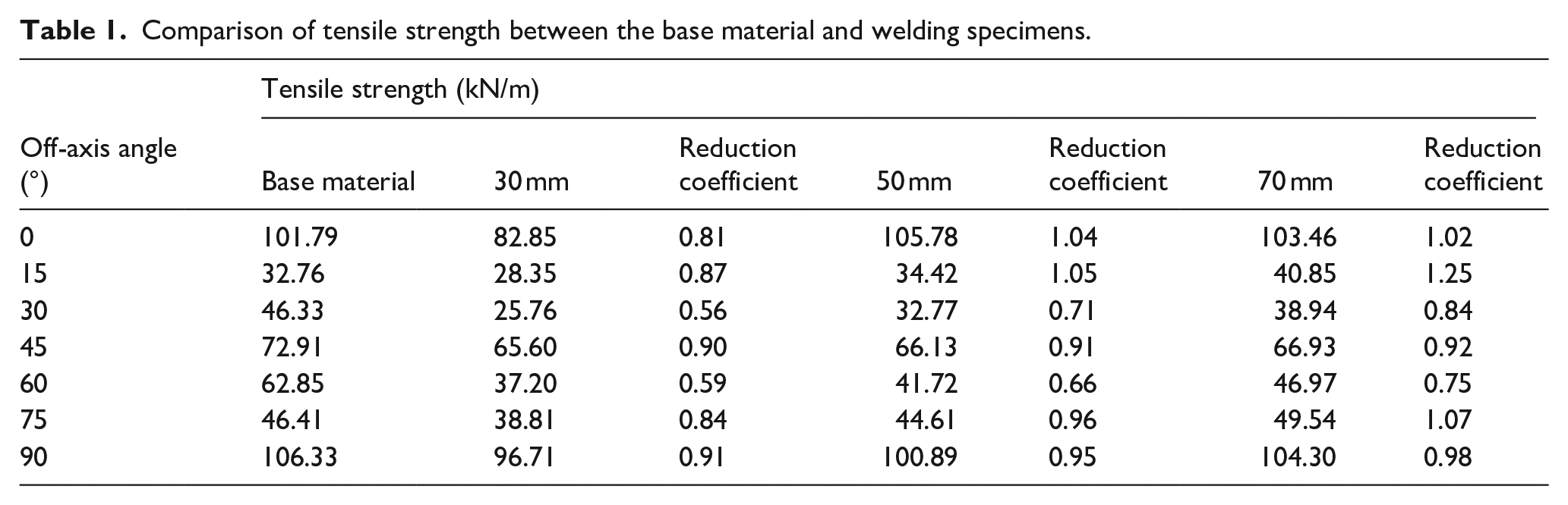
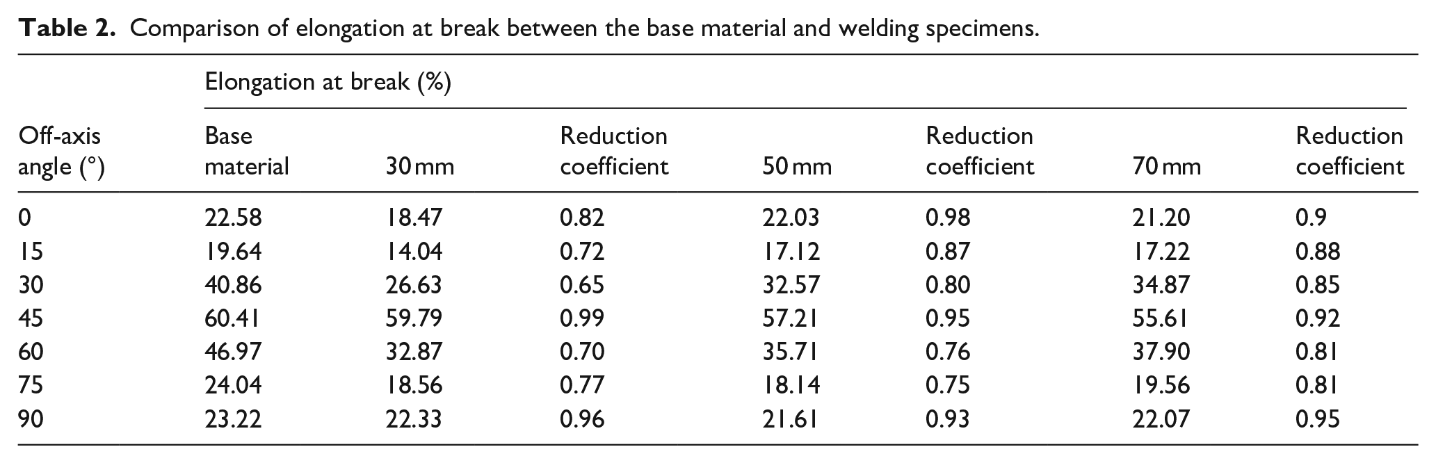
The comparison results of tensile strength and elongation at break between the base material and welding specimens are listed in Tables 1 and 2. The relationship curves between tensile strength and elongation at break and off-axial angle are shown in Figure 7. It can be seen that the tensile strength of base material and welding specimens shows a W-shape change and the elongation at break shows an inverted V-shaped as the off-axial angel increases. Both of them are basically symmetrically distributed in the 45°. In addition, the tensile strength and elongation at break of welding specimens are all less than that of base material, which indicated that welding will cause strength reduction and stiffness mutation. The strength reduction of 30° and 60° specimens is the largest. That of the 30 mm welding length specimen at the off-axial angle of 30° is only about 55.6% of the base material, and others are more than 0.8.
Comparison of tensile strength between the base material and welding specimens.
Comparison of elongation at break between the base material and welding specimens.

Off-axial tensile strength and elongation at break of base material and welding specimens: (a) tensile strength, (b) elongation at break.
Effect of welding length
Figure 8 shows the relationship between off-axial tensile strength, elongation, and welding length of specimens. It can be seen that the tensile strength of each off-axial specimen increases with the welding length increases. The tensile strength of the 30 mm welding length specimen with a 30° off-axial angle is the minimum, which is only 55.6% of the base material strength. While the tensile strength of the 70 mm welding length specimen can reach over 80% of base material strength. In addition, the elongation at break of welding specimens also depends on the final failure mode. The elongation at break of these specimens that the damage mainly occurs in the base material (the specimens with 0°, 45°, and 90° off-axial angles) is slightly decreased caused by stiffness increase with the increase of welding length. While for these specimens with 15°, 30°, 60°, and 75° off-axial angles, the failure process is accompanied by debonding and sliding of the welding section, so the elongation at break of these specimens increases with the increase of welding length.

Relationship between off-axial tensile strength, elongation, and welding length: (a) tensile strength, (b) elongation at break.
To sum up, in the design process of membrane structures, special attention should be paid to the mechanical performance of the welding section in the non-main axis direction. If two membrane materials are close to the main axis of the material (0°, 15°, 75°, and 90°) and the welding length is greater than 30 mm when they are welded, the strength reduction coefficient of the weld can be safely taken as 0.8, otherwise, the reliability of the weld shall be determined by testing. In addition, the deformation coordination between the non-welding section and the welding section should be fully considered. So, the welding length should not be too long, it is appropriate to meet the load requirements of the welding.
Failure modes and failure mechanism
The off-axial tensile failure mode can be divided into three types: yarn breakage, shear failure, and composite failure. Based on test results, the off-axial tensile failure mode of welding specimens is significantly different from that of the base material. Most of the failure parts are concentrated in the welding section. Figure 9 shows four failure modes in this test, yarn extract, yarn breakage (in the weld edge and in base material), shear failure, and composite failure.

Failure modes of off-axial welding specimens with different welding lengths: (a) 0°, (b) 90°, (c) 45°, (d) 15° and 75°, (e) 30° and 60°.
The yarn extract failure mainly occurs in warp specimens with 30 mm welding length, which is a brittle failure. The fracture is usually located at the edge of the welding section and distributed perpendicular to the load direction, which form shows as the warp yarn is extracted from the welding section. The typical specimens see also the first one in Figure 9(a) and (b). This is because of the weaving method of the membrane and the lack of anchoring length of the warp specimen. Figure 10 shows the weaving process of the plain weave. In this method, the long and straight warp yarn is tensioned as the main yarn, and the orthogonal weft yarn is interwoven up and down around the warp yarn. Therefore, the warp yarn in the finished membrane remains basically straight, while the weft yarn has inflection points (shown in Figure 11). In addition, the welding section has greater stiffness than the base material, which may be easy to form stress concentration at the edge of welding section.

Schematic diagram of plain wove.
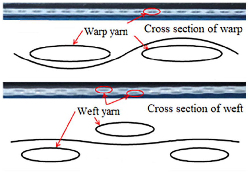
Cross section of warp and weft yarn.
The yarn breakage failure mainly occurs in warp and weft specimens with 50 mm and 70 mm welding lengths. It could be divided into yarn breakage failure in weld edge and yarn breakage failure in base material according to the difference in failure location (shown in Figure 9(a) and (b)). These specimens occur brittle failure, with flat and perpendicular fracture surfaces distributed in the direction of the load, and a little yarn is extracted from the fracture surfaces. Because the warp yarn is thick and straight, while the weft yarn has a thin and high curl. When the warp specimens are failure, due to the constraint effect of the weft yarn, the fracture position of the warp yarn is relatively concentrated and the fracture surfaces are straight. But there is still a small amount of warp yarn extracted. In the process of tensile of weft specimens, there will have an “exchange curl.” The weft yarn is straightened while the warp yarn is curled. Finally, the weft specimens break straight along the line of the curl point connection and the fracture surfaces are particularly neat. In this type of failure mode, the proportion of yarn breakage in the weld edge is relatively large. This is because of stress concentration caused by sudden stiffness changes at the edge of the welding section.
The shear failure mainly occurs in off-axial specimens with 45°, which is a brittle failure. The tensile strength and failure rule of specimens with three welding lengths is basically consistent. The fracture is concentrated on the base material near the welding section. The fracture characteristics are similar to those of base material, which can be divided into two types: slanting and V-shaped. In this failure mode, the yarn at the edge of the fracture surface is extracted while the yarn in the middle is cut off (shown in Figure 9(c)). Figure 12(a) shows the tensile failure process of the off-axial specimen with 45°. It can be seen that the base material undergoes large deformation, while the strain of the welding section is small due to its high stiffness. The damage in this specimen first occurs at the edge of the base material near the four corners of the welding section. Then it continues to expand at the edges of the base material until this specimen fractures. This may be because, during the welding process, the coating of the base material at the edge of the welding section is significantly damaged. When the load is raised to a certain level, the four corners of the base material near the welding section are firstly damaged due to stress concentration and shear bond failure. However, it is worth noting that not all initial damage cracks in the base material at four corners will develop into through cracks. Among them, cracks extending toward the welding section will stop expanding due to the obstruction of the welding section. Therefore, it can be inferred that the welding has a certain crack-stopping effect on the propagation of membrane cracks.

Tensile failure process of off-axial specimens: (a) 45°, (b) 75°.
The composite failure is the tensile-shear mixture mode, which mainly occurs in off-axial specimens with 15°, 30°, 60°, and 75° (shown in Figure 9(d) and (e)). The damage is concentrated on the welding section, including yarn extracted in the weld edge, local coating peeling, and base material curl. Figure 12(b) shows the tensile failure process of off-axial specimens with 75°. It can be seen that during the loading process, the weft yarn of base material tends to deflect in the direction of the load, while also being constrained by the geometric constraints of warp yarn and the bonding constraints of base material, resulting in a tensile-shear coupling stress state. But due to stress hysteresis of the welding section caused by coating fusion and stiffness mutation, the welding section undergoes a deflection in the same direction as the main load-bearing yarn (weft), protruding to the left. The damage of these specimens starts at the edge of the base material near the corners of the welding section. In this damage, the partial weft yarn is extracted from the base material, the coating in this area is peeled off from the substrate, and part of the substrate undergoes curling. For the specimens with 70 mm welding length, most of them are partial yarn extracted or breakage failure due to tensile-shear coupling and local stress concentration, few of them have a coating peeling phenomenon. Namely, when the welding length is 70 mm, the welding specimens typically experience material failure rather than connection failure.
Conclusions
This paper presents the research on the off-axial failure analysis of PVC-coated fabrics welding seam under different welding lengths. The following conclusions are drawn from the present study.
As the off-axial angle changes from 0° to 90°, the tensile strength changes in a W-shape while the elongation at break changes in an inverted V-shape, and the distribution is symmetrical at about 45°. The tensile strength and elongation at break of welding specimens are all less than that of base material. The strength reduction of 30° and 60° specimens is the largest, which is about 0.5–0.7. That of the 30 mm welding length specimen at the off-axial angle of 30° is only about 55.6% of the base material. Others are more than 0.8. These indicated that welding will cause strength reduction and stiffness mutation.
The off-axial tensile failure mode of welding specimens is significantly different from that of base material, which could be divided into four types: yarn extract, yarn breakage (in the weld edge and in base material), shear failure, and composite failure. The causes of the formation of various failure modes mainly include the weaving method of the membrane, the stress state of the element, the welding length, the interfacial shear strength of yarn and coating, the welding heat effect, and the local stiffness mutation.
In the design process of membrane structures, special attention should be paid to the mechanical performance of the welding section in the non-main axis direction. If two membranes are close to the main axis of the material (0°, 15°, 75° and 90°) and the welding length is greater than 30 mm when they are welded, the strength reduction coefficient of the weld can be safely taken as 0.8, otherwise, the reliability of the weld shall be determined by testing. In addition, the deformation coordination between the non-welding section and the welding section should be fully considered.
Footnotes
Funding
The author(s) disclosed receipt of the following financial support for the research, authorship, and/or publication of this article: The funding for this investigation was provided by the National Natural Science Foundation of China (No.51678563), the Universities “Green and Blue Project” Young and Middle aged Academic Leaders in Jiangsu Province’s (2024), and the National Natural Science Foundation of China (No.5237082006).
Declaration of conflicting interests
The author(s) declared no potential conflicts of interest with respect to the research, authorship, and/or publication of this article.
Date availability statement
The data that support the findings of this study are available from the corresponding author upon reasonable request.