
Abstract
Inspired by the multi-layered structure found in banana pseudostem, an innovative bionic pseudostem-like multilayer weft-knitted spacer fabric (ML-WKSF) was proposed for the development of high-performance and mass-produced personal protective materials. ML-WKSFs with different spacer filament diameters (0.15, 0.175, and 0.2 mm) were produced on a computerized flat knitting machine, incorporating thermoplastic filaments during the knitting process to enhance structural supporting of the spacer filaments. In both flat compression and fatigue compression tests, the ML-WKSF with 0.15 mm filament exhibited superior compressive resistance and fatigue resistance due to the more compact fabric structure resulting from the smaller diameter monofilaments, which facilitated uniform stress distribution. Additionally, composite fabrics were prepared using a shear thickening fluid (STF) with a SiO2 mass fraction of 70%, and mechanical property tests were conducted. The composite fabrics displayed similar trends to the pure fabrics in both flat compression and fatigue compression tests. Differently, the integration of STF with the monofilaments led to an increase in compressive load bearing capacity. In low-velocity impact tests, larger spacer filaments resulted in better impact resistance for the fabrics as the impact force was locally dispersed. The composite with 0.2 mm spacer filaments demonstrated excellent impact resistance and energy absorption, achieving an energy absorption efficiency of 69% at an initial impact energy of 40 J.
Keywords
Introduction
High-performance human body protection materials play a crucial role in ensuring human safety and preserving physical health, with growing demand across various sectors. Whether in military, industrial, medical, or sports fields, people are constantly seeking more advanced and effective protective materials to shield the human body from various potential harms. In recent years, remarkable progress has been made in the research of high-performance protective materials. However, these materials are not without flaws. Metal or ceramic materials, despite having relatively high strength and hardness, which are heavy and uncomfortable to wear. 1 High-strength fiber composites such as carbon fiber-reinforced composites and aramid fiber composites have become a research focus in protective materials due to their excellent strength-to-weight ratio and impact resistance.2–6 The preparation process of high-strength fiber composites is complex and costly, which significantly restricts their large-scale application. Consequently, developing materials that ensure high protection performance while being lightweight, flexible, and suitable for mass production is a key research area in the current field of protective materials.
Biological materials have been an endless source of inspiration for developing novel materials and structures in recent decades. By utilizing exquisite structures instead of chemical complexity, biological materials surpass their synthetic counterparts in many properties and functions. The key to efficiently secure these outstanding properties lies in their hierarchical structure, that is, how the structural elements or building blocks are arranged and organized at multiple length scales. 7 The design of bionic protective structures often mimics the characteristics of animal shells, plant tissues, or other organisms in nature, which have developed excellent mechanical capabilities through long-term evolution. For example, the structure of animal scales8,9 and crustacean exoskeletons10–12 have extremely high impact resistance, and the layered structure of shells13–15 exhibits excellent crack resistance. Through the biomimetic design of these biological structures, researchers have developed a series of high-strength and flexible protective materials. In recent years, the research on bionic plant structure materials16–19 has gradually emerged. The fiber hierarchical structure of the banana tree pseudostem 20 provides an important inspiration for developing new high-performance protective materials. Banana pseudostem is composed of multiple layers of fiber bundles,21,22 each of which is connected by a natural adhesive to form a highly layered composite structure. This layered structure can not only effectively disperse external forces but also has good flexibility and stability. In addition, pseudostem fibers have low density and high strength properties.23,24 This multi-layer structure provides important insights for the design of modern protective materials, especially in terms of how to integrate multi-layer structures and avoid interlayer peeling. At present, only few works investigate the mechanical behavior of the naturally designed of the structure of the banana trees and emulate the structure for engineering application.
Spacer fabric (SF), similar to banana tree pseudostem, has attracted extensive attention as a new type of fabric material. Spacer fabrics have a unique three-dimensional structure, which is composed of two independent fabric layers and an intervening spacer layer, giving fabrics many advantages. 25 SFs can effectively disperse and absorb energy when subjected to external forces, providing great cushioning performance,26–30 and their composites also have excellent mechanical properties.31–34 They also have good air permeability, 35 which can reduce the stuffiness of users when wearing protective equipment. Recently, researchers have continued to explore different preparations and combinations of spacer fabrics to further enhance their protective properties and other functional properties. It is well known that multi-layer fabrics are an important branch of protective materials. Compared with single-layer fabrics, they can effectively disperse impact energy and improve overall protective performance.36–38 Traditional multilayer fabrics usually consist of layered structures of different materials, and the material and structural design of each layer have specific functions. However, this layered structure is prone to delamination or interlayer detachment when subjected to high-strength impact, 39 significantly affecting the protection effect. In addition, the preparation process of multi-layer fabrics is relatively complex and usually requires special equipment and techniques, which not only increases the production cost but also limits their large-scale application.
Inspired by the structure of banana pseudostem, an innovative multi-layer weft-knitted spacer fabric (ML-WKSF) was designed to develop high-performance human protective materials that can be mass-produced (Figure 1). ML-WKSF simulates the multi-layer structure of banana pseudostem by connecting four surface layers through three spacers (Figure 1(b)). Mass production can be realized on computerized flat knitting machine equipped with four needle beds (Figure 1(c)). The weft knitting technology of integrated forming is adopted to ensure better bonding force between the layers to solve the problem that traditional multi-layer fabrics are prone to delamination. During knitting, the hot melt filament is combined with the monofilament, and the melting characteristics are used to improve monofilaments supporting and enhance fabric structural stability. In addition, in order to further improve the impact resistance of the fabric, shear thickening fluid (STF) was used as the filling material to prepare the composite fabric. STF shows a unique strain-thickening characteristic when subjected to impact,
40
which can rapidly enhance the impact resistance of the material while maintaining flexibility. This study focuses on the influence of different monofilament diameters on the compressive and impact resistance of ML-WKSFs and their composites. Through systematic experimental research, the relationship between monofilament diameter and fabric properties is revealed, providing a theoretical basis for optimizing fabric structure and properties. It is hoped that through the bionic design of banana tree pseudostem structure, a high-performance human protective material with excellent performance, low cost and simple preparation process will be developed, providing new ideas and solutions for the development of protective equipment and better protect people’s lives and health. Structure of ML-WKSF. (a) Banana tree and pseudostem; (b) structure diagram of ML-WKSF; (c) computerized flat knitting machine; (d) physical picture of ML-WKSF.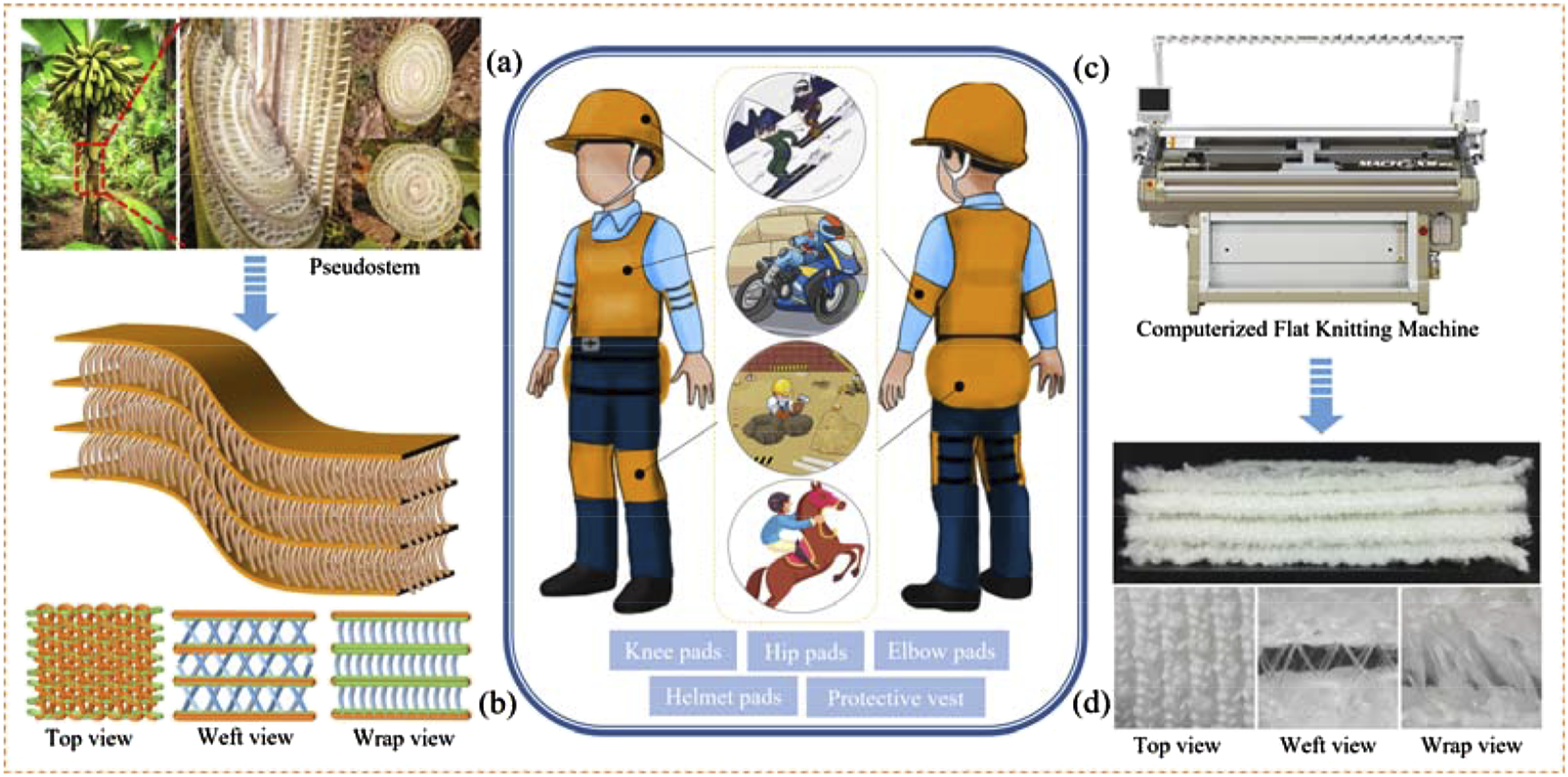
Materials and method
Materials
Polyester monofilaments with different diameters of 0.15 mm, 0.175 mm, and 0.2 mm were purchased from Zhejiang Jinxia New Materials Technology Co., LTD (Jinxia, Zhejiang Province, China). 40/70 spandex covered yarns were procured from Jiaxing Xinhai Textile Co., LTD (Jiaxing, Zhejiang Province, China). The 100D low-temperature polyester thermal fuse with a melting point of 110°C was provided by Fujian Jinhaosheng Textile Technology Co., LTD (Quanzhou, Fujian Province, China). 666dtex/192F DTY polyesters were supplied by Hengli Petrochemical Co., LTD (Dalian, Liaoning Province, China). The spherical nano-silica particles used were purchased from Zhejiang Manli Nanotechnology Co., Ltd (Ningbo, Zhejiang Province, China), having an average primary particle size of 300 nm and a SiO₂ content of more than 99.99%. Polyethylene glycol (PEG) with an average molecular weight of 600 g/mol and absolute ethyl alcohol were purchased from Sinopharm Chemical Reagent Co., LTD.
Manufacturing of ML-WKSF
Six kinds of ML-WKSFs with different spacer diameters were produced on SHIMA SEIKI WHOLEGARMENT MACH2XS (Figure 2(a)), which is equipped with three multifunctional systems and a four-bed configuration. The structure and fabric of ML-WKSF are shown in Figures 1(b) and (c), and the parameters of each sample are presented in Table 1. All samples have the same multilayer structure, and the samples are different in the spacing monofilaments diameter. Fabrics without hot-melt filaments are type A, while fabrics with hot-melt filaments are type B. The variation of monofilament diameter of samples A1-A3 and B1-B3 is 0.15 mm, 0.175 mm and 0.2 mm, respectively. For fabrics with a small monofilament diameter, the density is greater, making the fabrics tighter. The fabrics with hot-melt filaments have smaller thickness because the hot-melt filaments generate tension and adhere to the monofilaments during the hot-melt process, while simultaneously shortening the thickness of the space layer. (a) SHIMA SEIKI WHOLEGARMENT MACH2XS machine; (b) Structure of ML-WKSF; (c) physical picture of ML-WKSF. Basic parameters of six samples.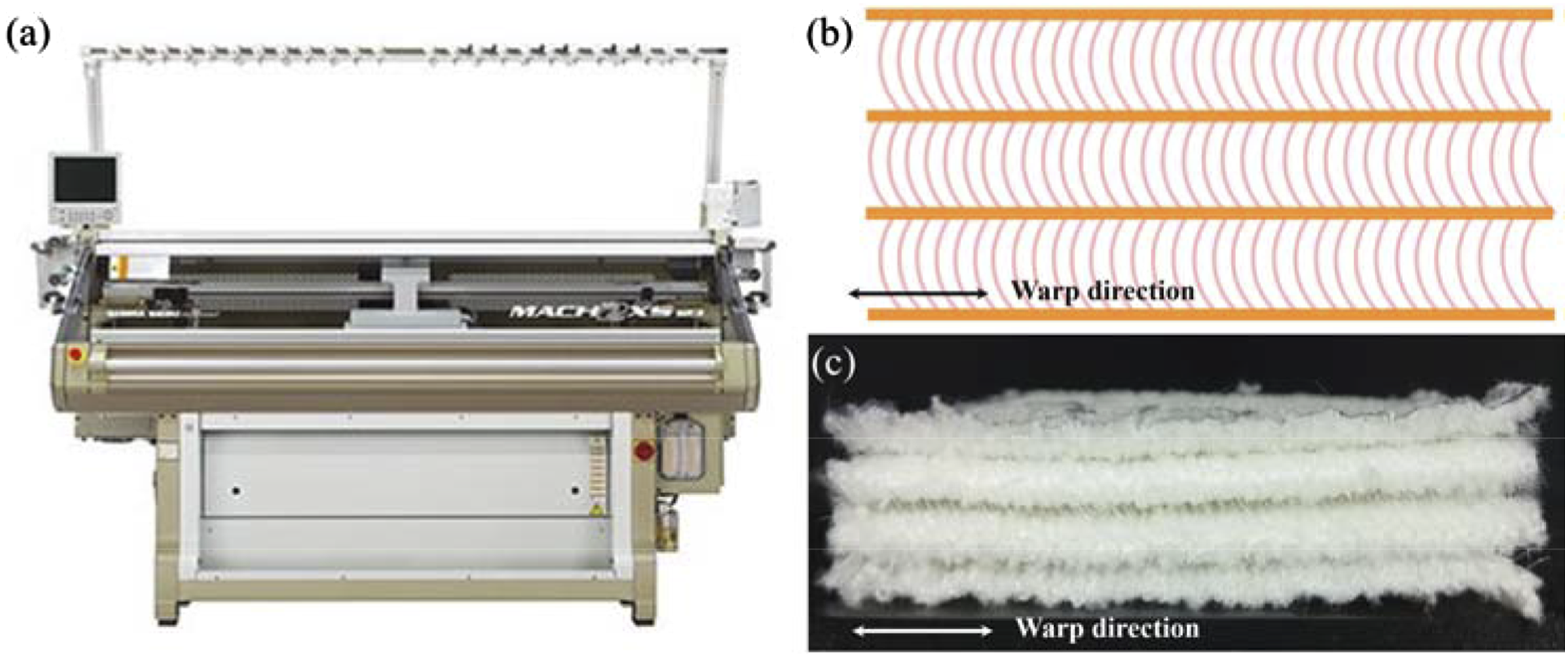

Preparation of STF and ML-WKSF composites
The STF components consisted of nano-particles and a carrier. PEG was selected as a solvent due to its non-toxicity, low volatility, and thermal stability. 40 Before use, the silica particles were oven-dried for 2 hours at temperatures above 100°C, enabling the removal of moisture. Each suspension was prepared by adding small amounts of silica to PEG in a blender several times and mixing for approximately 2 hours. All samples were placed in a vacuum chamber at room temperature for around 24 hours to eliminate the bubbles.
To facilitate the impregnation process, the highly viscous STF needs to be diluted with ethanol. Diluting STF with ethanol enhances the wettability of fabrics with STFs by reducing both the viscosity and the surface tension of the STF. The volume ratio of STF to ethanol was optimized to 1:4. The fabrics could be cut into pieces with dimensions of length × width = 100 mm × 100 mm and then immersed in STF for 5 minutes to ensure that the STF adequately penetrates into the fabrics and the excessive fluid is removed. Subsequently, the composite fabrics are dried at 80°C for at least 6 hours to evaporate the excess ethanol. 41 The composites of type B are named STF-B1, STF-B2, and STF-B3.
Characterization and mechanical testing
The structure of the fabric was observed using an optical microscope (RX20-9108, Runxing Optical Instrument Co., Ltd, Shenzhen, Guangdong Province, China). The microstructure and morphology of SiO₂ nano-particles, pure ML-WKSFs, and their composites were analyzed by means of a field emission scanning electron microscope (FE-SEM, Supra 55, Zeiss).
Rheological tests were carried out by a rheometer HAAKE MARS60 (TA Instruments-Waters LLC). A parallel-plate with a diameter of 20 mm was employed for the test in an environment of 20°C and 65% relative humidity. To ensure accurate measurement of rheological behaviors, any excess STF outside the test section was trimmed off prior to testing. Steady-state strain rate sweeps of STFs were measured in the shear rate range of 0.01 to 1000 s⁻1. 42
All ML-WKSFs were tested under a standard atmospheric environment with a temperature of 20 ± 2°C and relative humidity of 65% ± 2%. According to GB/T24442.1-2009, the quasi-static compressive tests were conducted by MTS Exceed E43 (MTS Systems (China) Co., Ltd, Guangzhou, Guangdong, China). The cross-section diameter of the plate was 20 cm, and samples’ size was 100 mm × 100 mm. The tests were carried out by means of constant compression rate. All samples were compressed to 20%, 40%, 60% and 80% of the original thickness by pressing plate at a compression and recovery speed of 2 mm/min, respectively.
All samples were compressed 1000 times with heavy pressure through constant pressure method to evaluate the fatigue-resistance properties according to FZ/T01051.2-1998 by using MTS Exceed E43 (MTS Systems (China) Co., Ltd, Guangzhou, Guangdong, China. The size of samples was 100 mm × 100 mm and speed of compression and recovery were 20 mm/min. The pressure is 50 kPa. 37
The low-velocity impact properties of STF-impregnated fabrics were conducted on the STLH-300 drop-weight low-velocity impact tester from Jinan Shangtai Test Instrument co., LTD (Jinan, Shandong, China). Using an impact head with a diameter of 12 mm, the total mass of the hammer was 1.968 kg. Setting the low-speed impact energy to 10J, 20J, 30J, and 40J and the drop hammer falls freely from a certain height. The low-velocity impact dynamic response of the ML-WKSFs would be analyzed and compared.
Results and discussion
Structure and surface morphology analysis
Structural simulation diagram of ML-WKSF is showed in Figure 3, including the surface layer, space layer and interlocking joint. It can be seen that the innovative ML-WKSF features three spacer layers that connect four surface layers. There are two organizations in surface layer, and tuck loops are knitted at intervals. The tucks are knitted on the side where the surface layers come into contact with the spacer filaments. Consequently, both the upper and lower sides of the two middle surface layers feature tuck stitching, whereas only the inner sides of the top and bottom surface layers possess such stitching. As a result, the two middle surface layers are thicker. Structural simulation diagram of ML-WKSF.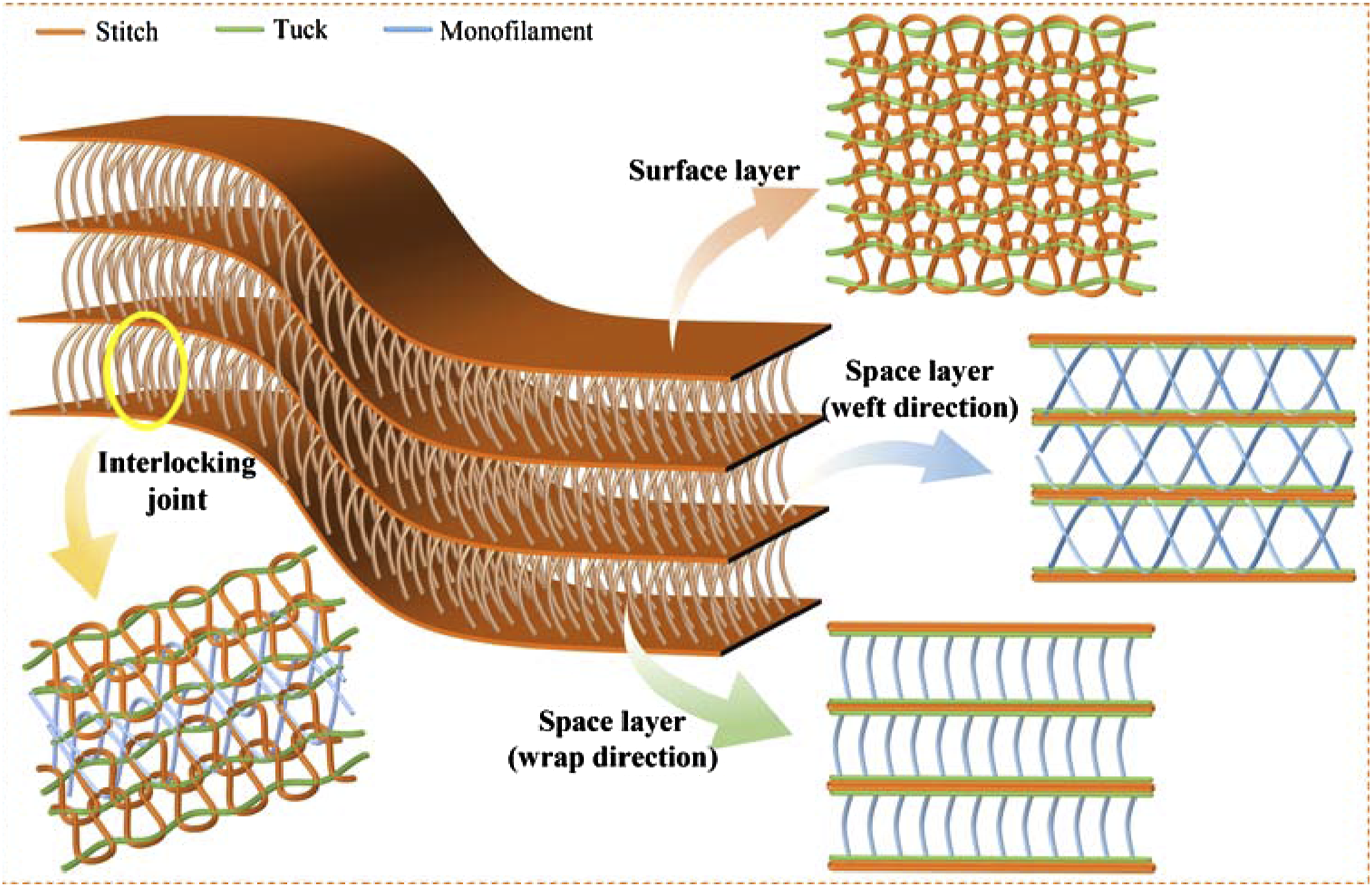
It presents the detail diagrams of ML-WKSF in Figure 4. As observed in Figures 4(a) and (b), the space layers are composed of a large number of monofilaments, and voids exist between these monofilaments, which like the structure of banana pseudostem. The surface layer is formed by the simplest stitch structure (Figure 4(d)). The joints of the surface layer and the monofilaments of the spacer layer are interconnected to form a mechanical interlocking structure (Figure 4(c)). This interlocking structure is beneficial for distributing stress, regulating energy dissipation at the interface, and enhancing mechanical properties. The densely structured surface layer can improve the overall structural stability. Meanwhile, the spacer monofilaments can disperse the applied stress effectively, and the joint points between them can also improve interface performance and prevent cracking or delamination among elements. Meanwhile, the multilayer structure can enhance the overall performance. In sum, ML-WKSF shows great structural advantages. (a) Cross section of ML-WKSF in warp direction; (b) cross section of ML-WKSF in weft and warp direction; (c) interlocking joint between surface layer and space layer; (d) coil structure of surface layer.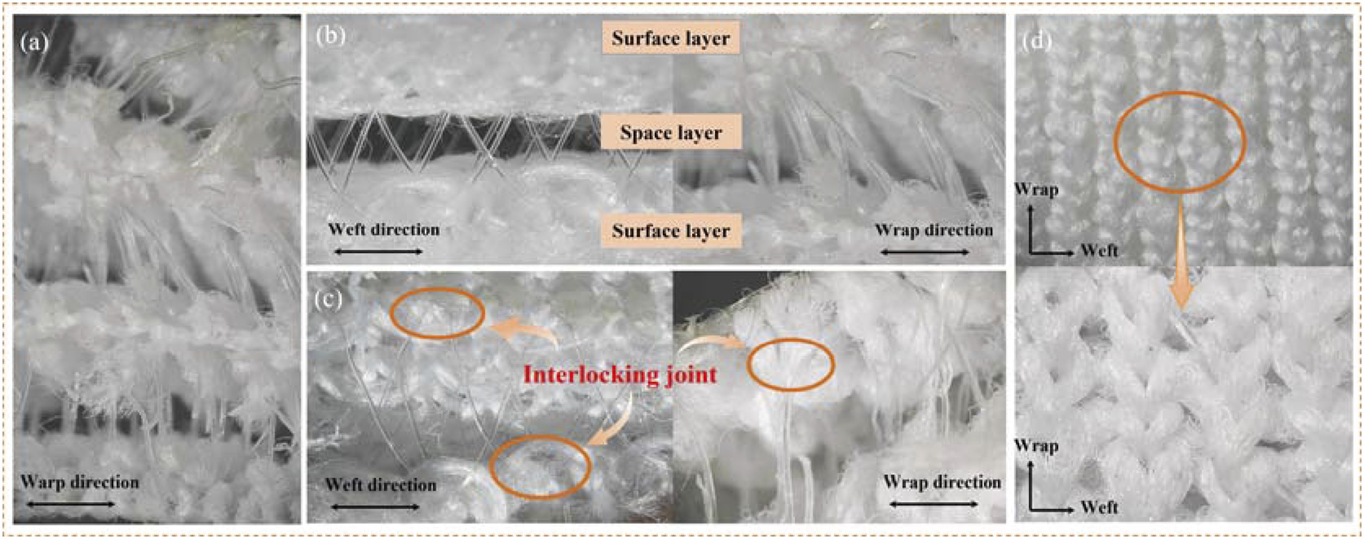
As shown in Figure 5, there are the surface morphologies of materials. Figure 5(a) presents the spherical morphology of SiO₂ nanoparticles. Figures 5(b) and (c) show the SiO₂ particles in the STF after the removal of ethanol, which are well adhered to PEG. Figure 5(d) – (f) are pure yarns. Figure 5(e) is the monofilaments with hot-melt filaments adhered. The untreated fiber surface is smooth, and the monofilament with hot-melt filaments adhered is significantly thicker. Figures 5(g)–(i) show the surface of the monofilament with hot-melt filaments composited by STF. It can be observed that STF exists on the monofilament surface and the SiO₂ particles are uniformly distributed. Due to the presence of hot-melt filaments and STF, the surface of the yarn becomes rough and gullies appear. Figures 5(j)–(l) are the surface of polyester multifilaments impregnated with STF. There is obvious adhesion of STF. The SEM images indicate the successful preparation of STF and its good impregnation effect on the fabric. Surface morphology of (a) SiO2; (b) SiO2 in STF; (c) STF on fiber; (d) pure monofilament; (e) polyester monofilament with hot-melt yarn; (f) pure multifilament; (g) monofilament with hot-melt yarn and STF; (h) and (i) STF on composite monofilament; (j) multifilament with STF; (k) and (l) STF on composite multifilament.
Mechanical properties of pure ML-WKSF
Compressive properties
Figures 6(a) and (b) present the compression behavior of fabrics A and B, respectively. In the experiment, the fabrics are compressed to 20%, 40%, 60%, and 80% of their initial thickness. The results indicate that fabric A exhibits a greater thickness compared to fabric B. Under different compression ratios, both fabrics demonstrate varying degrees of deformation. Figures 6(c) and (d) illustrate the stress-strain curves for six samples at different compression ratios. The compression process is linear. Compression process of (a) type A fabrics; (b) type B fabrics; stress-strain curves under a compression ratio of (c) 20%; (d) 40%; (e) 60%; (f) 80%.
In the initial phase of compression, the load increases linearly with displacement. However, due to the relatively loose structure of the knitted outer layer, the initial slope of the stress-strain curve is low. As displacement increases, the fabrics undergo rapid densification, resulting in a sharp rise in load. This causes the internal filaments of the fabric to collapse and make extensive contact with the outer layers, resulting in higher stiffness. During the compression process, the spacer filaments buckle, leading to a swift transition from the initial linear compression phase to the densification phase. Overall, fabric B, which contains thermoplastic fibers, exhibits substantially higher compressive stress resistance compared to fabric A, which lacks thermoplastic fibers. The presence of thermoplastic fibers significantly improves the compressive performance of the fabric, further demonstrating that the mechanical properties of spacer filaments play a crucial role in determining the overall performance of such fabrics.
At a compression ratio of 20% (Figure 6(a)), fabrics with a monofilament diameter of 0.2 mm (samples A3 and B3) exhibit the highest compressive stress, regardless of the presence of thermoplastic fibers in the spacer layer. During the initial stage of slight compression, the bending of the spacer filaments is minimal, allowing them to play a key supporting role, with the thicker filaments bearing greater loads. When compressed to 40% of the original thickness (Figure 6(b)), the fabric containing thermoplastic fibers, sample B2 (monofilament diameter of 0.175 mm), exhibits the highest compressive stress. Meanwhile, for fabrics without thermoplastic fibers, sample A3 maintains the best compressive performance. As compression ratio increases, at 60% and 80% compression (Figures 6(c) and (d)), the strain on the fabric intensifies, and for both fabric types, samples with a monofilament diameter of 0.15 mm demonstrate superior compressive performance. The structural parameters of the fabrics reveal that smaller monofilament diameters correlate with higher surface layer density. Since the monofilaments are interlinked with the surface layer loops, fabrics with a denser surface layer contain more filaments in the spacer layer, resulting in enhanced structural stability. Therefore, a smaller monofilament diameter, accompanied by a higher filament count, leads to a more compact surface layer. As fabric strain increases, the load borne by the spacer filaments rises accordingly, with the filaments effectively dispersing the stress. The increased density of the surface layer also contributes to improved structural stability. Notably, fabrics with a monofilament diameter of 0.15 mm exhibit the highest filament count in the spacer layer and the greatest surface layer density, thereby bearing the highest compressive stress.
Fatigue-resistance compressive properties
Figure 7 presents the results of the fatigue-resistance compressive tests. Figures 7(a) and (b) compare the performance of fabrics A and B before and after 1000 compression cycles under a constant pressure of 50 kPa. It can be observed that fabric A, due to its greater thickness, experiences larger deformation during the test. In contrast, fabric B, reinforced with thermoplastic filaments, shows smaller deformation. Figures 7(c) and (d) illustrate the stress-strain curves for six different fabrics during the first and the 1000th compression cycle. Similar to quasi-static compression, the process is also linear, transitioning directly from linear compression to the densification phase. Generally, fabric B exhibits superior compressive fatigue resistance compared to fabric A. Compression cycles process of (a) type A fabric; (b) type B fabric; stress-strain curves at the first and 1000th compressions of (c) type A fabric; (d) type B fabric.
As shown in Figure 7(c), the three different diameters of fabric A exhibit minimal differences in strain under a pressure of 50 kPa. However, after 1000 compression cycles, all samples undergo significant deformation, with a notable loss in thickness. In Figure 7(d), it is evident that for fabrics with thermoplastic filaments adhered to the monofilaments, the fabric B1, with a monofilament diameter of 0.15 mm, experiences the least deformation after 1000 compression cycles. However, under severe compression, fabrics may collapse, and the spacer filaments buckle, leading to a sudden drop in stress, followed by a rapid increase as strain continues to rise. The presence of thermoplastic filaments enhances the support provided by the monofilaments, and, combined with the higher fabric density and greater yarn content per unit area, results in improved mechanical performance. Therefore, under a 50 kPa pressure, the fabric with a 0.15 mm diameter exhibits the best compressive fatigue resistance, followed by fabrics with diameters of 0.175 mm and 0.2 mm, respectively.
Mechanical properties of STF-ML-WKSF composites
Rheological behavior of STF
The steady-state shear response of STF with silica weight fractions of 55%, 60%, 65%, and 70% is illustrated in Figure 8. It can be observed that the STF exhibits a characteristic shear-thickening effect. Initially, at low shear rates, shear thinning occurs, where the viscosity decreases with increasing shear rate. Subsequently, a transition to shear thickening is observed, and the viscosity sharply increases once the critical shear rate is reached. Finally, shear thinning resumes, with viscosity moderately decreasing as the shear rate continues to rise. Dispersions with higher weight fractions show a higher initial viscosity and a more pronounced increase in viscosity. When the silica content in STF reaches 70%, the peak viscosity rises from 1.379 Pa·s for the 55% STF to 157.1 Pa·s, while the critical shear rate decreases from 520.2 s⁻1 to 78.52 s⁻1. As the shear rate increases, the shear stress increases linearly and shows a significant rise at the critical shear rate. Additionally, the 70% STF demonstrates a higher yield stress of 18,250 Pa, compared to the yield stress of only 125.1 Pa for the 55% STF at 139.1 s⁻1. Due to the superior shear-thickening performance of the 70% STF, it was selected for composite material preparation in subsequent experiments. Rheological behaviors of the STF for (a) viscosity-shear rate curves; (b) shear stress-shear rate curves.
Compressive properties
The compression process of the B-type fabric impregnated with STF under compression rates ranging from 20% to 80% is depicted in Figure 9(a), while Figures 9(b)–(e) show the corresponding stress-strain curves for three types of composite fabrics. For the composite fabrics, it is evident that regardless of the compression rate, STF-B1 exhibits higher stress, followed by STF-B2 and STF-B3. This suggests that composites with smaller filament diameters can withstand greater forces. This trend is consistent with the compression behavior of pure fabrics, where smaller filament diameters result in higher surface and interlayer density, leading to greater overall fabric stability and improved compressive resistance. (a) Compression process of STF composite; stress-strain curves under a compression ratio of (b) 20%; (c) 40%; (d) 60%; (e) 80%.
The compression process of STF-reinforced composite fabrics is similar to that of pure fabrics, with an increased compressive load. This increase arises from the additional force required to squeeze the STF to the fabric’s outer layer, as well as the enhanced coupling effect between the STF and the filaments. At low compression rates (5 mm/min), the STF remains in a shear-thinning state, making it easily extruded from the fabric. Notably, at a high compression rate of 80%, the compressive load of the composite fabric is lower compared to that of the pure fabric. This reduction is due to the uneven force distribution caused by the extrusion of STF within the fabric structure. Overall, STF composite fabrics with a filament diameter of 0.15 mm demonstrate superior compressive performance.
Fatigue-resistance compressive properties
Figure 10(a) shows a comparison of the composite fabric STF-B before and after 1,000 compression cycles under a constant pressure of 50 kPa. Figure 10(b) displays the stress-strain curve of fatigue compression tests. It can be seen that the STF-impregnated composite fabrics don’t experience any crushing. The initial linear region during the compression process decreases, and the stress increases rapidly with strain. At a compression rate of 20 mm/min, the STF remains in a shear-thinning state. Due to the adhesion of the STF, there is an increase in thickness and support in both the surface and spacer layers, allowing the fabric to withstand greater stress without crushing. After 1,000 compression cycles, the deformation of the composite fabrics is smaller compared to pure fabrics. Given the supporting of the spacer filaments (either from thermoplastic fibers or STF), an increased number of filaments improves the fatigue resistance to compression. Therefore, under 50 kPa, the fabric with a 0.15 mm filament diameter exhibits the best fatigue resistance, followed by those with diameters of 0.175 mm and 0.2 mm, which is consistent with the compression behavior of plain fabrics. ML-WKSFs with thermoplastic fibers demonstrate superior fatigue resistance compared to those without. Among them, STF composite fabrics with thermoplastic fibers exhibit the best fatigue resistance to compression, with STF-B1 showing the optimal performance. (a) Images of the STF composites before and after 1000 compression cycles; (b) stress-strain curves at the first and 1000th compressions.
Low-velocity impact properties
Low-velocity impact tests were conducted on ML-WKSFs impregnated with STF composite materials. The impact process can be divided into three stages: In the first stage, a drop hammer of a specific mass moves freely from a designated height, converting gravitational potential energy into kinetic energy. In the second stage, the hammer falls freely, reaching its maximum velocity upon first contact with the composite material. As the hammer continues to interact with the composite material, its speed gradually decreases. When the velocity reaches zero, the hammer has reached its lowest point, completing the impact. During this second stage, the composite material gradually unfolds and absorbs energy.
Figure 11 illustrates the post-impact morphology of three types of ML-WKSF composites under initial impact energies of 10 J, 20 J, 30 J, and 40 J (corresponding to initial impact velocities of approximately 2.15, 3.18, 3.89, and 4.49 m/s, respectively). All of the impacted fabrics exhibit varying degrees of bulges. These deformations are particularly pronounced at impact energies of 30 J and 40 J. Since the applied impact energies are below the damage threshold under all conditions, no perforation occurred in the ML-WKSF composites. During the low-velocity impact test, due to the interlocking effect between the surface layer and spacer layer loops as well as the stability of the multi-layer structure, neither the yarn breakage nor the loop disentanglement occurred. Meanwhile, no delamination was observed among the multiple layers. The overall structure of the fabric remained stable. During the impact process, the impact force was transmitted layer by layer. As a result, the yarns and loops underwent deformation to absorb the impact energy, which led to the fabric deformation exceeding its elastic limit and failing to restore to its original shape, that is, plastic deformation occurred. Obvious depressions appeared on the fabric. Moreover, the higher the impact energy was, the more pronounced the deformation became. Under the same impact energy, the sample STF-B3 exhibited the smallest deformation. This indicates that a thicker diameter of the spacer yarn can provide better support for the fabric during the impact process, thereby making the overall structure of the fabric relatively stable. Impact morphologies of the STF composites.
Figures 12(a)–(d) display the impact load-displacement curves for three composite material samples. In general, the contact load increases linearly with the displacement. As the impact energy increases, the slope of the contact force also increases, reaching the maximum contact force in a short period of time. This indicates that the composite materials become stiffer with increasing impact energy. Figure 12(e) shows the peak loads for all tests. It can be seen that from 10J to 20J of impact energy, the peak load of the composite fabrics increases, particularly for STF-B3, where the load rises from 0.777 kN to 3.267 kN, an increase of approximately 4.2 times. The peak loads of the other two fabrics also more than doubled. However, during the impact from 20 J to 40 J, the load of each composite material begins to decrease. The maximum contact load of STF-B3 decreases from 3.267 kN to 1.488 kN, a reduction of approximately 2.2 times. Moreover, at 40 J, the load-displacement curve shows some fluctuation, which is attributed to the pronounced thickening effect of the STF at higher impact velocities, enhancing the damping effect and thereby improving the cushioning performance. Load-displacement curves of the STF composites under an initial impact energy of (a) 10 J; (b) 20 J; (c) 30 J; (d) 40 J; (e) peak impact load.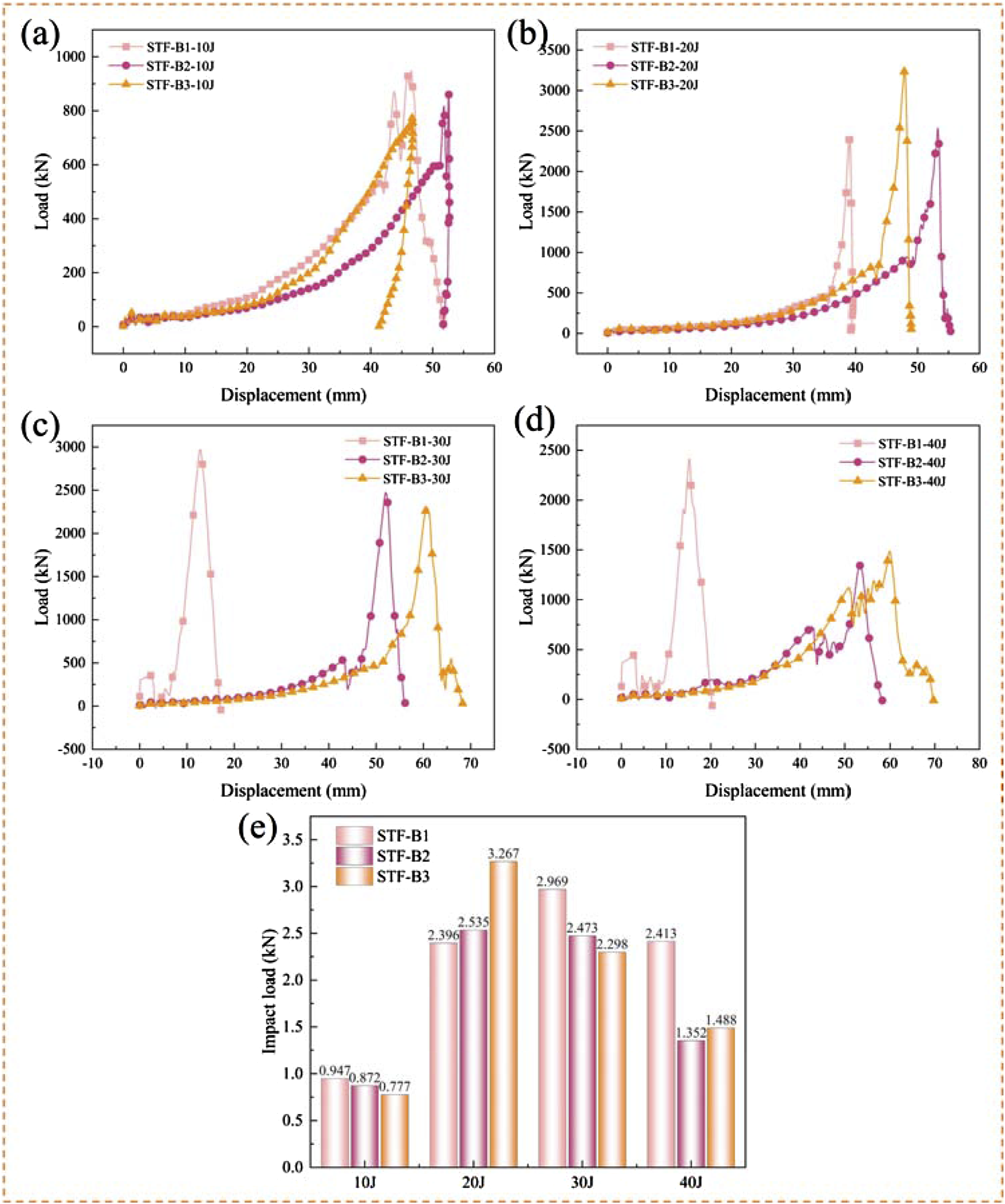
For the composite fabrics, the load increases slowly in the early stages as the impact force is transmitted downward through the layers. The individual filaments in the fabric undergo buckling, shearing, rotation, mutual contact, collapse, and surface contact. As the fabric compacts, the contact load reaches its peak, with the multilayer fabric being compressed locally, causing a significant rate of load increase. The multilayer structure of the fabric enhances the cushioning effect, while the shear thickening behavior of the STF contributes to the increased damping effect, thereby improving the impact resistance of the composite fabrics.
Energy absorption
Figure 13 illustrates the energy-displacement curves and peak energy absorption for all tested samples. Under an impact energy of 10J, the difference in energy absorption among the three composite materials is minimal. The sample with a filament diameter of 0.15 mm achieves an energy absorption rate as high as 98.7%, demonstrating excellent cushioning performance. However, at 20 J impact energy, the energy absorption of the 0.15 mm sample drops to less than 50%, while the other two composite materials maintain energy absorption rates of around 99%. At impact energies of 30 J and 40 J, the energy absorption rates of all three samples begin to decrease. The impactor rebounded, and the samples were not broken, resulting in a partial energy loss. Higher impact energy leads to increased energy loss. Despite this, the STF-B3 composite fabric with a 0.2 mm filament diameter still exhibits an energy absorption rate of up to 69% under high-impact conditions. This is attributed to the enhanced thickening effect of STF at higher impact speeds, resulting in greater damping and better cushioning performance. Overall, STF-B3 demonstrates excellent energy absorption performance across impact energies ranging from 10 J to 40 J. Energy-displacement curves of the STF composites under an initial impact energy of (a) 10 J; (b) 20 J; (c) 30 J; (d) 40 J; (e) peak impact energy.
As the initial energy increases, fabrics with larger filament diameters exhibit better energy absorption and cushioning performance. While fabrics experience uniform stress distribution during flat compression, the stress during impact is localized. During the impact process, cushioning and resistance are primarily provided by the supporting performance of the filaments and the shear-thickening effect of the STF. Filaments with smaller diameters are more prone to bending and buckling under instantaneous impact, leading to relatively poorer impact resistance. In conclusion, the diameter of the spacer filaments significantly affects the impact resistance and energy absorption performance of composite fabrics, with larger-diameter filaments offering better energy absorption and cushioning capabilities.
Conclusion
Inspired by the layered structure of banana pseudostem found in nature, a series of novel biomimetic ML-WKSFs were designed and produced using weft-knitting technology, varying in monofilament diameters. The fabrics were subsequently impregnated with STF to create composite fabrics. The effects of monofilament diameter and STF impregnation on the mechanical properties of these fabrics were then analyzed. The main conclusions are summarized as follows:
For the pure fabrics, the compression process during both the flat plate compression tests and fatigue compression tests exhibited a linear behavior, consisting of an initial linear stage followed by a densification stage. Under high compression strain, fabrics with smaller monofilament diameters (more filaments per unit area) bore higher compression loads, due to the higher filament density that effectively distributes in-plane stress. Fabrics reinforced with thermoplastic filaments demonstrated better compression performance. After 1000 cycles of heavy loading, spacer filaments exhibited significant collapse. Sample B1, with a monofilament diameter of 0.15 mm, showed the best compression and fatigue compression performance, attributed to its high filament count, compact surface layer, stable structural dimensions, and minimal deformation under pressure.
STF with a SiO2 weight fraction of 70% demonstrated an excellent shear-thickening effect during steady-state rheological experiments. As a result, the composites of ML-WKSF were prepared by using 70% STF. For these composite fabrics, the mechanical properties under flat plate compression and fatigue compression tests were consistent with those observed in the pure fabrics. Small-diameter monofilaments similarly exhibited greater stress under high compression strain. However, the coupling effect between the STF and the monofilaments in the composite fabrics increased the compression load capacity, thereby enhancing performance. In low-velocity impact tests, fabrics with larger spacer filaments showed better impact resistance as the impact energy increased. Sample STF-B3 exhibited outstanding impact resistance and energy absorption capabilities, as the larger diameter spacer filaments could bear higher loads during localized impacts, while the STF’s shear-thickening effect improved energy absorption, reducing the load and enhancing cushioning performance.
Footnotes
Acknowledgments
The authors acknowledge the financial support from the National Nature Science Funds of China (52373058), Postgraduate Research & Practice Innovation Program of Jiangsu Province (KYCX24_2566) and the Applied Foundation Research Funds of China Textile Industry Association (J202408).
Declaration of conflicting interests
The author(s) declared no potential conflicts of interest with respect to the research, authorship, and/or publication of this article.
Funding
The author(s) disclosed receipt of the following financial support for the research, authorship, and/or publication of this article: this work was supported by the financial support from the National Nature Science Funds of China (52373058), Postgraduate Research & Practice Innovation Program of Jiangsu Province (KYCX24_2566) and the Applied Foundation Research Funds of China Textile Industry Association (J202408).