
Abstract
Using Abaqus finite element software, this study investigates the impact of different carcass belt layer structures on the grounding characteristics of tires. Focusing on the 215/55R17 radial tire, the research proposes a structural optimization scheme and establish a finite element model. The standard tire belt layer structure is replaced with a mesh belt layer structure to achieve optimized performance. Through static loading tests on the tire, the accuracy of the finite element model was validated. By altering the density, number of layers of the mesh belt structure, and radial load of the tire, a simulation analysis is conducted to study the impact on tire deformation and stress on the carcass material. The optimized tire features increased radial stiffness and reduced tread wear. The density of the mesh belt layer in the contact area affects tire deformation as well as the stress on the belt layer and ply layer. The results indicate that the mesh belt layer can effectively absorb the radial load of the tire, optimizing tire deformation by 20% to 30%. Under different loads, the tire with a 70-density mesh belt layer can reduce surface stress by approximately 40%, or around 230J. The mesh belt layer tire can reduce the sensitivity of the tire center to high load stresses, optimizing 25% of the concentrated stress at the shoulder position of the ply layer. When a double-layer belt is used, the strength at the shoulder increases with the number of belt layers, reducing stress by approximately 2-4N. The structural form of the belt layer has little impact on the trend of stored strain energy changes, but the number of belt layers significantly affects the amount of change in the tire’s strain energy. On average, about 10% of the stored strain energy is reduced due to changes in the belt layer structure.
Keywords
Introduction
The tire belt layer, as the primary structure bearing the forces on the tire, directly influences the tire’s ground performance. Serving as the structure between the tire’s inner belt layer and carcass ply, the belt layer is one of the main load-bearing structures, bearing 60%-75% of the tire’s stress. 1 A well-designed tire structure can significantly enhance the tire’s lifespan and reduce vehicle vibrations under the same rubber material usage and manufacturing conditions. 2
Luwen Chen utilized the dynamic longitudinal slip of the tire to observe fluctuations and asymmetry in the cord force with increasing velocity. 3 Lv et al. optimized the mechanical performance and structure of self-supporting safety tires. 4 Cui studied the influence of belt layer expansion on tire footprint. 5 Liu proposed two approaches to optimize both the tire crown and tread, aiming to synergistically enhance tire grip and wear performance.6,7 Huang utilized high styrene hard elastomer layers as the skeletal material to enhance the load-bearing capacity and ground contact of non-pneumatic tires. 8 Wang studied the quantitative relationship between ground parameters and dry-wet conditions, providing guidance for tire structural design. 9 Kong analyzed the impact of tire tread arc height on ground performance. 10 Ding proposed a diamond-hexagon-diamond composite material tire and analyzed its load-bearing capacity, ground contact performance, fatigue life, and rolling state. 11 Zhou et al. conducted tests on tires with different pressures and loads using a five-rigidity testing machine and a Tirescan pressure distribution testing system. They concluded that the deflection is closely related to the ground contact performance of the belt layer and the tire. 12 Roque concluded that contact stress measured by a rigid base apparatus is suitable for assessing the response and performance of highway pavements. 13 Manyo established a model for simulating road surface stress and compared it with experimental results. 14 Oubahdou utilized a rapid semi-analytical method to simulate tire-road contact, revealing the significance of contact parameters in pavement surface degradation. 15 Chenliang achieved the evaluation of wet traction performance of radial tires by obtaining eight ground contact characteristic parameters. 16 Cuong, Do Minh, and Sihong Zhu investigated the influence of different ground contact conditions and inflation pressures on the vertical natural frequencies of tires using the free decay method. 17 Zhang utilized the structural characteristics of kangaroo limbs and employed a non-inflatable tire unit configuration method to establish a biomimetic non-inflatable tire model. The study found that the performance of the flexible spoke biomimetic non-inflatable tire was superior to that of the inflatable tire structure. 18 Yu et al. analyzed the tire-road contact pressure under different driving conditions, investigating the influence of vehicle load and tire pressure on tire contact pressure distribution under static vehicle loading. They simulated the variation of tire contact pressure with vehicle speed or time under steady rolling, driving, and braking conditions. 19 Hermange et al. proposed a three-dimensional fluid-structure coupling between Smoothed Particle Hydrodynamics (SPH) and Finite Element Methods (FEM), applied it to simulate complex tire hydroplaning on rough surfaces, and emphasized that road surface roughness can lead to an increase in fluid loading, which is a reason for loss of contact between the tire and the ground. 20
These scholars have investigated various factors influencing tire-ground contact performance. However, few have proposed optimizing tire-ground contact performance by altering the internal structure of the tire.
This study delves into the mechanical properties of tires by conducting uniaxial tensile testing on tire materials to ascertain stress-strain parameters. With this data, suitable constitutive models were chosen, and finite element models of the tires were constructed using software like ABAQUS. The feasibility of the finite element model was verified through comparisons with static load experiments. Subsequently, the finite element model underwent optimization and refinement, proposing an optimization strategy for a meshed belt layer structure. A comparative analysis between the conventional belt layer structure and the meshed belt layer structure was carried out within the finite element models. The investigation particularly explored the impact of the meshed belt layer structure on tire-ground contact performance. This study contributes to the continuous development of tire engineering practice and highlights the importance of advancing tire design methods to meet the evolving needs of modern automotive applications.
Material performance experiments
In material performance experiments, the physical parameters obtained are the data basis for establishing the finite element model. The obtained data is used to define material properties using finite element software to achieve simulation comparison effects of the model, and the effectiveness of the finite element model is verified by comparing it with experimental data.
Rubber material experiment
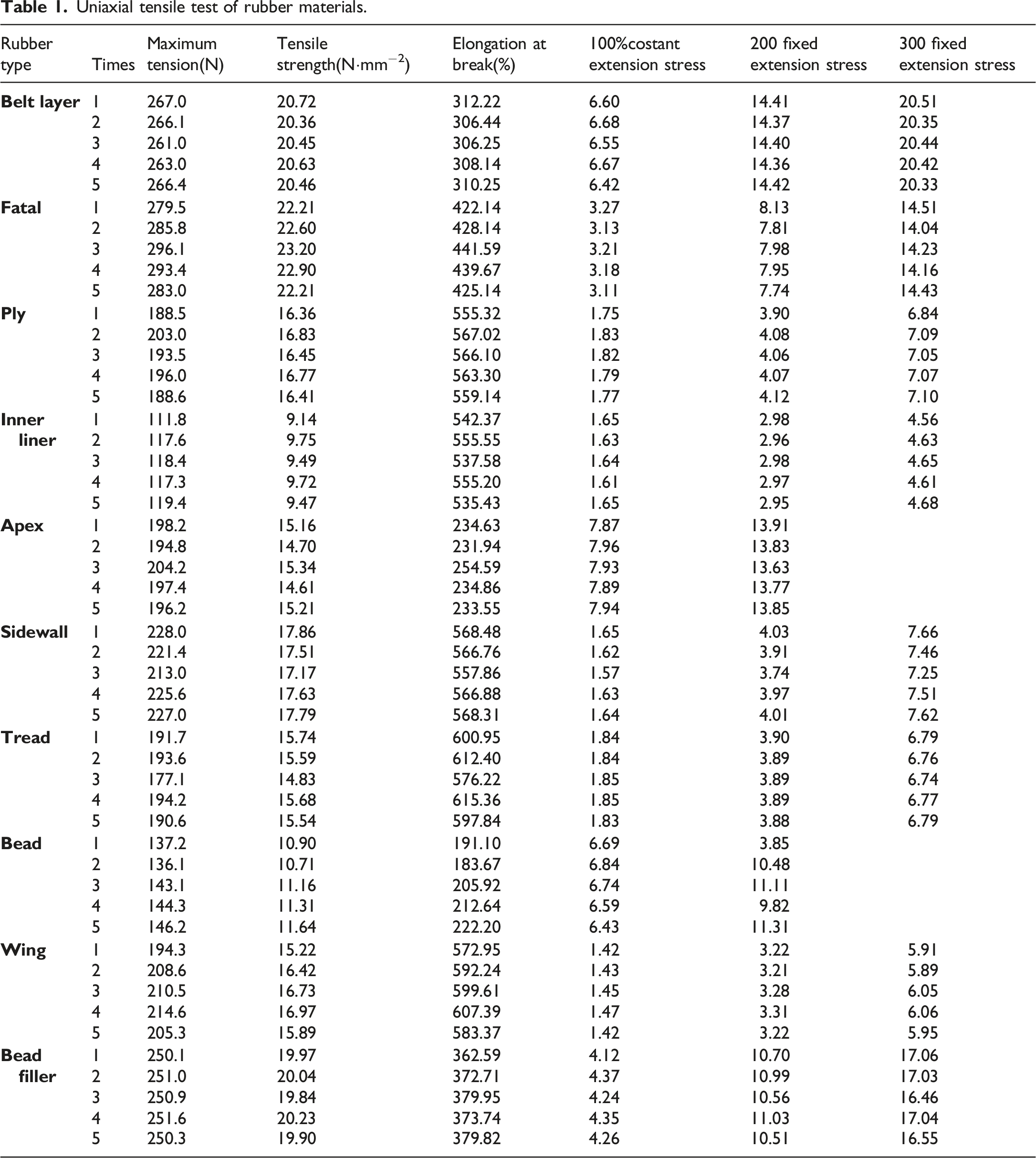
Rubber materials, being nearly incompressible elastic bodies, require specialized constitutive models for definition. ABAQUS software provides various rubber constitutive models. This paper selects the commonly used Yeho, Mooney-Rivlin, and Neo-Hooke constitutive models for fitting. Uniaxial tensile tests are conducted on various rubber materials of the tire using a high-low temperature tensile testing machine. The rubber specimens are processed into dumbbell shapes, and all rubber specimens are standardized after vulcanization, as shown in Figure 1(a). The specimens are placed in a 25°C environment for 24 h before testing to avoid temperature effects on the test results. Uniaxial tensile tests are performed on samples of various parts of the tire rubber material, as shown in Figure 1(b) and Figure (c). The tire rubber material samples were processed into a dumbbell shape according to GB/T-528, as shown in Figure 2. The thickness of the specimens ranged from 2.0 mm ± 0.2 mm, with the central testing area measuring 25 mm × 6 mm × 2.5 mm. Uniaxial tensile test of Tire rubber material. The dimensions of the uniaxial tensile test samples.

Uniaxial tensile test of rubber materials.

Rubber stress-strain curve.
The constitutive equation for the Yeoh, Mooney-Rivlin, Neo-Hooke model is as follows:


The parameter Cij represents the shear characteristics of the material.
Yeoh model parameters for different rubber materials.

As this paper primarily focuses on the tread area, the stress-strain curve of the rubber material is presented using the tread rubber as an example, which is the most suitable primary model material. Through the fitting results of the model as shown in Figure 4, it is found that the Yeoh model fits the tread rubber most closely. Therefore, the Yeoh model is selected. Fitting of constitutive model.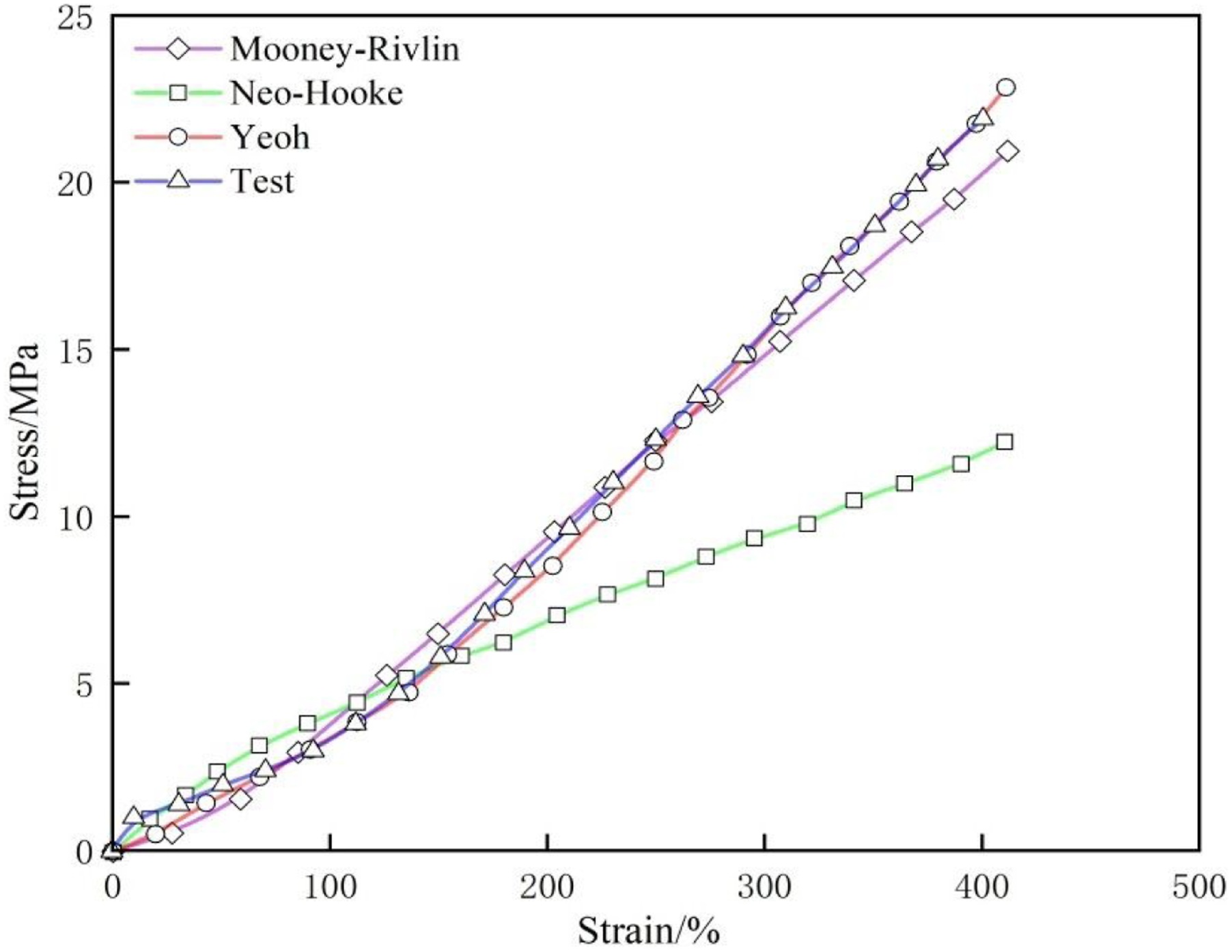
Skeleton material experiment
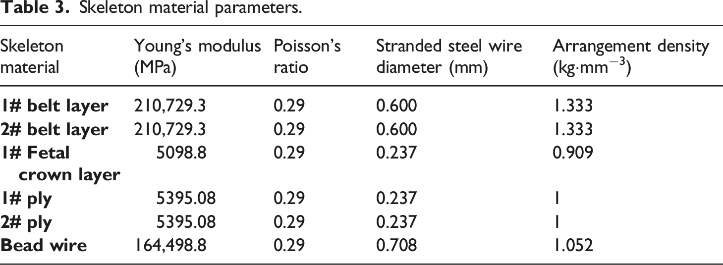
The tire carcass is filled with a composite material consisting of rubber and cord, including steel cord and nylon cord. Select tire sample materials for uniaxial tensile material experiments on the carcass, as shown in Figure 5. Tire carcass uniaxial tensile test.
Skeleton material parameters.
Model establishment
Finite element model of the tire
The cross-section of the sample tire is obtained through scanning, as shown in Figure 6(a). A two-dimensional (2D) cross-section of the tire is drawn using AutoCAD. Due to the complexity of the transverse tread pattern in tires, which may lead to convergence issues in calculations, only longitudinal tread patterns will be considered for modeling. The material data obtained from material performance experiments will be used to define material properties for each component in Abaqus software and then meshed. The Fetal crown layer, ply layer, and belt layer are embedded into the model using the *embedded command. The 1/2 (2D) model is symmetrically meshed using the reflect and faces commands in Hypermesh software, as shown in Figure 6(b). Finally, the *SMG command is used to rotate the smooth tire around the 2D cross-section by 360° to obtain a 3D tire model, as shown in Figure 6(c). The finite element model of the tire is verified to have a total of 202,803 elements, including 166,300 rubber elements and 36,503 reinforcement elements. At this stage, the rubber material elements are of type C3D8RH (three-dimensional elements), and the reinforcement elements are of type SFM3D4 (surface elements). The finite element model of the tire established by this method can effectively reduce stress at mesh transition regions and improve the accuracy of stress on the carcass fibers during the calculation process.
21
Establishment of finite element model.
Meshed belt layer
Fundamental curve equation for meshed belt layer.

By using the expressions shown in Table 4, generate the baseline curve using regular curves, stretch the baseline curve, and rotate the stretched body by 1.8°. Then, create one clockwise and counterclockwise spiral each along the Z-axis direction. Project the two spirals onto the stretched body. Finally, import the geometry into Abaqus in IGES format, generate two projection lines, and array them along the Z-axis direction to form a meshed structure. Array the projection lines to create meshed structures with densities of 50, 60, and 70 respectively. The meshed structures are all designed with a 45° crossed structure to ensure convergence throughout the finite element calculation process. The meshed structures are shown in Figure 7. The modeling process and visualization of the meshed belt layer.
Set the established meshed structure to have the same belt layer material as the tire finite element model, and replace the belt layer structure. The tire finite element model after replacement is shown in Figure 8. Comparison of tire structures.
Model validation
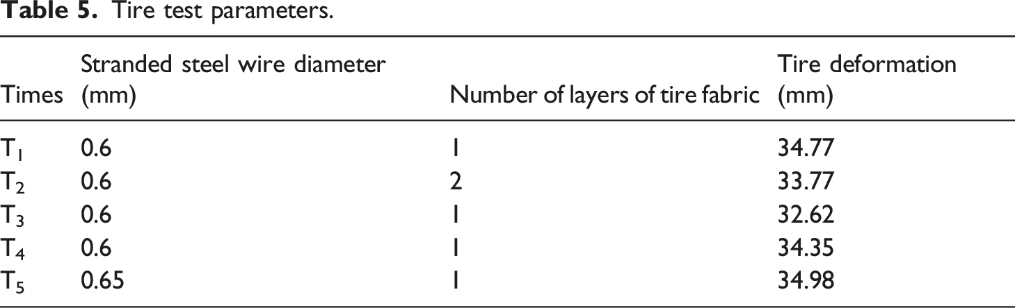
Static ground contact experiments are conducted using a five-rigidity testing machine, as shown in Figure 9(a). The tire pressure is set to 0.25 MPa, with fixed loads of 3 kN, 4 kN, and 5 kN. The ground contact stress of the tire is measured by the platform of the five-rigidity testing machine. The tire is fixed on the bearing platform and subjected to radial force. The tire loading process consists of three steps: (1) tire inflation, (2) rim pre-tightening, and (3) radial loading, as illustrated in Figure 9(b) The finite element model of the tire is fixed in the same way as in the static ground contact experiment. The same inflation parameters are set, and radial force is applied on the radial plate to simulate the static ground contact state of the tire. Tire finite element model and grounding test.
Tire test parameters.
Comparison of experimental and simulation results.

Tire ground contact mechanical simulation analysis
The simulation conditions are set with a tire pressure of 0.25 MPa and vertical loads of 3 kN, 4 kN, and 5 kN, respectively. The meshed belt layer density is defined by the baseline array count when establishing the meshed belt layer, with values of 50, 60, and 70, respectively. For consistency in charts and figures, the term “RT” is used as a unified name for radial tires. The tire belt layer is one of the main load-bearing components of a tire, with the first layer showing the most pronounced performance. For the sake of consistency in observation and research, the first layer of the meshed belt layer is selected as the primary research subject. Although the second or third layers of the belt can also play a role in optimization, they primarily build upon the optimization of the first layer, serving as supplementary reinforcement. Therefore, they are not the main focus of this research and analysis.
Ground contact stress simulation and analysis
As shown in Figure 10, it can be observed that the deformation of both radial tires and meshed belt layer tires decreases to varying degrees with the increase in meshed structure density. The deformations of the radial tire under loads of 3 kN, 4 kN, and 5 kN are 12 mm, 18 mm, and 23 mm, respectively. When the meshed structure density is 50 and 60, the deformation of the tire decreases by about 20%. When the density reaches 70, the deformation decreases by around 30%. It can be observed that the deformation of the tire is inversely proportional to the density of the meshed structure. Meanwhile, it can also be concluded that the meshed structure can significantly increase the tire’s rigidity and reduce its hysteresis effect. The mesh structure, used as the belt layer of the tire, can positively influence the radial stiffness and deformation of the tire. In conclusion, the mesh belt layer structure can significantly enhance the rigidity of the tire, thereby reducing its deformation. The mesh structure, as an integrated system, forms a cohesive whole through its geometric arrangement and interlaced struts. This geometric configuration effectively distributes and transmits external forces. Under radial force, the force within each mesh unit is decomposed and transferred to adjacent struts, increasing the overall structural stiffness through this force transmission mechanism. Additionally, the mesh structure offers multiple pathways to disperse the load, rather than relying on continuous material in a single direction. Consequently, when the tire is compressed, forces can be dispersed along multiple paths, enhancing the tire’s radial stiffness. As the density of the mesh belt layer increases, this geometric reinforcement effect and the number of force transmission paths increase, positively impacting the tire’s stiffness and deformation. Grounding imprint.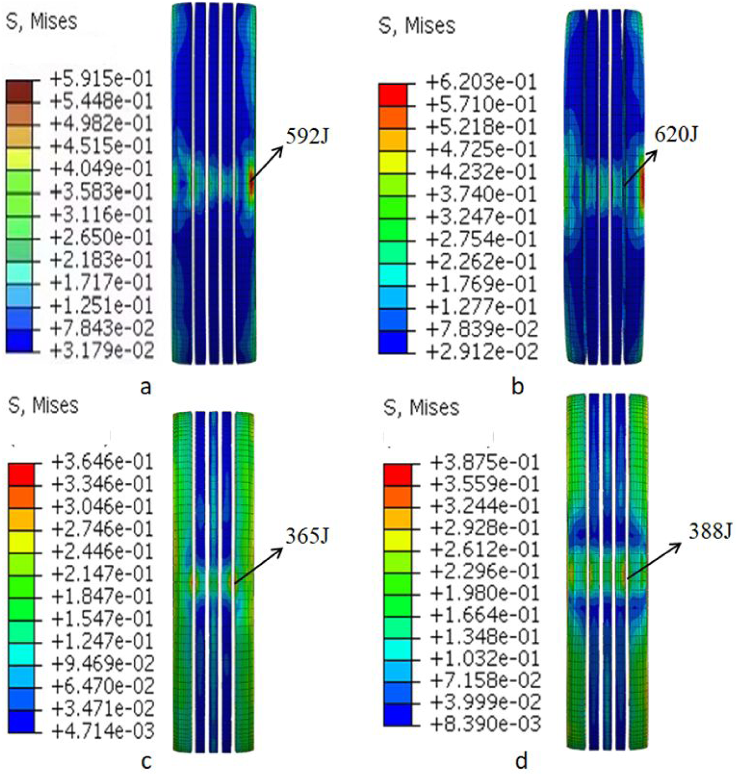
Combining with Figure 11 analysis, different degrees of deformation fluctuations occur on both sides of the tire center. This is because there are belt layers of different widths inside the tire, causing fluctuations in deformation on both sides of the center of the tire surface and the shoulder position. Tire deformation under different loads.
The maximum stress experienced by both radial tires and meshed belt layer tires on the surface increases with the increase in radial load. Under a radial load of 3 kN, the maximum stress on the surface of the belt layer tire with a density of 70 is 227 J less than that of the radial tire. Under a radial load of 5 kN, the maximum stress of the belt layer tire with a density of 70 decreases by about 40%, as can be seen in Figure 10. The meshed belt layer structure is more effective in absorbing tire stress compared to traditional radial tires. This helps reduce tire surface wear and improves the abrasion resistance of the tire surface rubber material. In Figure 10, it can also be observed that the meshed structure belt layer tire does not perform as well under stress at the shoulder as the radial tire. The reason for this is that the meshed structure and traditional radial tires absorb and transmit stress in different directions. When the meshed belt layer is subjected to a radial load, the structure collapses inward. While the meshed structure absorbs a significant amount of stress, it also transmits some stress to the shoulder region.
Stress analysis of ground contact skeleton materials
The ground contact skeleton structure includes the belt layer and ply layer, both of which are located in the inner area of the tire. The belt layer is the primary load-bearing structure, while the ply layer is the primary supporting structure. The stress variations in these structures are difficult to obtain through experiments. Therefore, finite element software is used to predict the stress state of the skeleton materials.
Changing the density and number of layers of the belt layer, as well as the radial load applied to the tire, observe the stress variations in the first layer of the belt layer and the first layer of the ply layer (Figure 12). As shown in Figure 12(a) and (c), the stress in the belt layer of the radial tire is 12% higher than that in the belt layer of the meshed belt layer tire under the same radial load of 3 kN. With the increase in meshed belt layer density, the stress decreases by 8 N and 11 N at densities of 60 and 70, respectively. When the radial load becomes 5 kN, the stress in the belt layer of the radial tire increases by approximately 20%, while the stress in the belt layer of the meshed belt layer tire increases by 6 N, 6 N, and 4 N at densities of 50, 60, and 70, respectively. It can be observed that the center position of the belt layer in the radial tire is sensitive to high stress, while in the meshed belt layer tire, it is the opposite. The stress at the center position is distributed to other locations, dispersing the concentration of stress. The maximum stress in the ply layer of the radial tire is 27 N and 30 N under radial loads of 3 kN and 5 kN, respectively. For the meshed belt layer tire, with the increase in belt layer density, the stress in the ply layer increases from 22 N to 24 N under a radial load of 3 kN and from 25 N to 29 N under a radial load of 5 kN. The maximum stress in the ply layer of both types of belt layer configurations occurs at the shoulder position. It can be concluded that the meshed belt layer optimizes the stress on the ply layer at the shoulder position. Additionally, on average, it can reduce the stress at the center position by about 25%. Comparison diagram of steel bar forces along the transverse path of the first layer tire skeleton material.
When using two layers of belt (Figure 13), it is observed that with the increase in the number of belt layers, the stress on the ply layer decreases correspondingly by two to 4N at the tire shoulder and tire center positions. Increasing the number of belt layers does not alter the distribution of stress on the ply layer. Increasing the number of belt layers only increases the strength at the corresponding locations of the ply layer. The analysis indicates that in the same working conditions, multiple belt layers can distribute more contact stress, improve the tire’s radial stiffness, protect the tire’s ground contact area, and extend the tire’s lifespan. Comparison of stress on the ply layer of double-layer belt tire.
The difference in the belt layer structure between radial tires and mesh-belted tires leads to the occurrence of such phenomena. The reason is that when subjected to high stress, the belt layer structure of radial tires absorbs a significant amount of stress, with the excess stress being directly transferred to the tire’s ply layer. The meshed belt layer forms an integrated ring structure that absorbs and distributes all the stress across various parts of the structure when under load. Excess stress is transferred through the ends of the structure to the tire sidewalls and the ply layer. This configuration results in superior static ground contact performance for meshed belt layer tires compared to radial tires. Consequently, the stress on the belt layer and ply layer at the same positions is lower in meshed belt layer tires than in radial tires. Additionally, this significantly optimizes the tire’s radial stiffness, increasing the maximum radial load the tire can withstand.
Combining the above analysis, it can be concluded that the belt layer of the meshed belt layer tire effectively absorbs the radial load of the tire, optimizes the stress on the ply layer at the shoulder position, and reduces the concentration of stress at the center position of the tire. A double-layered belt layer can significantly enhance the rigidity of the tire and increase its lifespan.
Simulation analysis of tire stored strain energy
Tires are formed from highly elastic rubber materials through varying degrees of vulcanization. Under normal circumstances, the deformation during tire inflation is minimal. Due to the special properties of tire rubber materials, tires can store strain energy under external forces. At constant temperature, the additional energy in the tire system equals the work done by external forces on the tire, as shown in equation (4):
The inflation pressure and radial force increase linearly over time. Each analysis step is set to 1 s. During the rim pre-tensioning process, both sides of the rim move uniformly towards the center of the tire by 13 mm. Figure 14 shows the variation of stored strain energy in both radial tires and meshed belt layer tires under different radial loads. Comparison of strain energy storage for three different loads of tires.
Analysis of Figure 14 reveals that by altering the meshed belt layer density, compared to radial tires, there is indeed a reduction in the variation of stored strain energy, by approximately 8%, 10%, and 20%. This indicates a close relationship between meshed belt layer density and the variation of stored strain energy, exhibiting a negative correlation. When comparing the variation of stored strain energy under different loads, it is observed that the change in load positively correlates with the variation of stored strain energy. That is, stored strain energy increases with an increase in load. However, the number of layers in the belt structure has a significant impact on the stored strain energy. As the number of layers in the belt structure increases, the stored strain energy decreases by 13%, 5%, 9%, and 11%, respectively. Changes in structural parameters do not alter the trend of stored strain energy variation. After the inflation and loading analysis steps are completed, there is a significant fluctuation in the stored strain energy. The inflation process reaches about 450 KJ, and there is an additional 50 KJ increase after loading is completed. Finally, the peak stored strain energy reaches about 500 KJ (a). At the moment of applying the load, the sudden change in external force causes a sudden change in the stored strain energy of the tire, leading to a slight decrease shortly after loading. When the number of belt layers in the tire increases, it is observed that the strain energy of the double-layer belt decreases by approximately 3%-6%, around 30-40 KJ, under the same radial load. Most of the load is absorbed by the meshed belt layer and transferred to the carcass ply layer, which increases the radial stiffness of the tire. This further reduces the energy changes between rubber molecules, resulting in a smoother variation of stored strain energy and a decrease in fluctuation frequency. This molecular change results in a significant variation in the stored strain energy of the tire. It also reflects the feasibility of utilizing strain energy to assess tire characteristics. It can be observed that both the number of layers and the density of the meshed belt layer significantly affect the stiffness of the tire, resulting in varying degrees of reduction in the stored strain energy of the tire.
Conclusions
After conducting comprehensive simulations and analyses on tire deformation, stress distribution in the skeleton materials, and stored strain energy, several key conclusions can be drawn:
Effect of meshed belt layer density on tire deformation and radial stiffness
- Adjusting the density of the meshed belt layer structure effectively controls tire deformation and optimizes radial stiffness. - Compared to radial tires, meshed belt layers of different densities can reduce tire deformation by an average of 7 mm and improve deformation optimization by 20% to 30%. - The meshed belt layer structure enhances the tire’s resistance to radial deformation and effectively absorbs surface stress on the tire tread, thereby reducing tread wear and enhancing the abrasion resistance of the tire’s surface rubber.
Absorption of radial loads and stress distribution
- The meshed belt layer in tires effectively absorbs radial loads. Increasing the density of the meshed belt layer allows it to distribute 12% to 20% more stress compared to radial tire belt layers. - At a density of 70, meshed belt layer tires can reduce surface stress by 227 J and 237 J under 3 kN and 5 kN loads, respectively. - The meshed belt layer reduces the sensitivity of the belt layer’s center position to high load stresses, thereby decreasing concentrated stress at the tire’s center. - It optimizes stress on the ply layer at the tire’s shoulder, reducing stress by approximately 25%, which increases the structural ply layer’s durability. - Using a double-layer belt reduces stress on the ply layer by 2-4 N at relevant positions, indicating that increasing the number of belt layers strengthens corresponding structural points.
Stored Strain Energy in Relation to Belt Layer Structure
- Changes in the belt layer structure effectively reduce stored strain energy in the tire, although the structure itself does not significantly alter the trend of stored strain energy. - Compared to radial tires, meshed belt layers can reduce stored strain energy by 8% to 20%. - Increasing the number of layers and density of the belt layer enhances tire radial stiffness. - The meshed belt layer absorbs most of the load and transfers it to the ply layer, reducing energy variations between rubber molecules. - This results in more stable changes in stored strain energy and a decrease in fluctuation frequency, demonstrating the feasibility of using strain energy to verify tire characteristics. - The number and density of mesh belt layers significantly impact tire stiffness, leading to varied reductions in stored strain energy.
In summary, the meshed belt layer structure proves highly effective in optimizing tire performance by reducing deformation, distributing stress more evenly, enhancing radial stiffness, and minimizing stored strain energy variations. These findings underscore the importance of structural design in improving tire durability and performance across various load conditions.
Future prospects
The introduction of a meshed belt layer as a novel structural scheme for tires, along with relevant experimental validations to provide accurate material data for establishing finite element models, marks a significant step forward. However, several practical challenges remain to be addressed in future research endeavors. These include: 1. Verification and Selection of Mesh Cross Structures: Further investigation is needed to verify and select optimal mesh cross structures at different angles, aiming to enhance tire performance and durability. 2. Integration of Different Rubber Formulations: Exploring the combination of the same belt layer materials with different rubber formulations can offer insights into improving tire properties, such as grip, wear resistance, and fuel efficiency. 3. Dynamic Testing for Longitudinal and Lateral Slip Performance: Utilizing dynamic test rigs to validate and study the longitudinal slip and lateral slip performance of mesh belt layer tires can provide valuable insights into their real-world handling characteristics. 4. Enhancement of Experimental Methods: Continual refinement of experimental methods is essential to ensure that results closely reflect real-world conditions, thereby enhancing the relevance and applicability of research findings. 5. Investigation of Mesh Structure Mechanical Properties: Further investigation into the specific mechanical properties of the mesh structure itself is crucial for gaining a deeper understanding of its role in tire performance and durability.
We anticipate that ongoing research in these areas will not only contribute to the development of new tire structures but also foster advancements in the automotive industry. By providing scholars with fresh perspectives and avenues for exploration, this research has the potential to drive innovation and propel the field forward.
Footnotes
Declaration of conflicting interests
The author(s) declared no potential conflicts of interest with respect to the research, authorship, and/or publication of this article.
Funding
The author(s) disclosed receipt of the following financial support for the research, authorship, and/or publication of this article: This work was supported by the Natural Science Foundation of Xiamen Municipality; (No.3502Z20227217), Science and Technology Research Project of Xiamen University of Technology; (No. YKJ22013R), Natural Science Foundation of Fujian Province; (No. 2023J011435), Research Project of Xiamen University of Technology; (No.XPDKT20026).