
Abstract
The production technology of one of the essential structural parts of rubber-textile conveyor belts, the textile carcass, has not changed much since the start of their use. Specific changes occurred only in the material used when various synthetic fibres gradually replaced cotton. However, with the development of additive technologies, the possibility of changing the production technology is coming to the fore, when industrial textiles produced by classic weaving will not be used to make the carcass but a structure built by 3D printing. Confirmation of this change would represent a revolutionary breakthrough in the technology for rubber-textile conveyor belt production. Based on these facts, the possibility of using continuous 3D printing technology was verified to print a structure that would replace the technical fabric used in the conveyor belt carcass. As part of the research, the Selective Laser Sintering (SLS), Fused Deposition Modeling (FDM), and Stereolithography (SLA) technologies were verified. Experimental specimens with the dimensions of 145 x 145 x 185 mm were produced in three different positions: at an angle (45°), horizontally, and vertically. The specimens were made of three types of filament: SLA (Elastic 50A), SLS (TPU 1301), and FDM (Flexfill 92A); for each of the three positions of the specimen, filament consumption and printing time were determined due to the use of support material. Created specimens were then assessed regarding their production possibility and achievement of the desired structure.
Keywords
Introduction
The structure of rubber-textile conveyor belts has not significantly changed in the entire period of their use. It consists of an upper covering layer, a lower covering layer, a carcass, and other additional structural elements that increase its resistance or improve the functional use of conveyor belts. The same applies to conveyor belt manufacturing technologies, where no fundamental changes have been implemented.
However, with the progress of knowledge in manufacturing technologies, more questions arise about whether it is not possible to replace the manufacturing procedures and technologies for rubber-textile conveyor belts and their structural parts with new, more progressive ones. These ideas are supported by the fact that new manufacturing technologies are gradually being promoted in various areas that were impossible until now, thus replacing formerly used ones.
Among the areas closely related to rubber-textile conveyor belts, with an enormous potential for additive technologies’ application, is the manufacturing of various textile materials. However, research on additive technologies use in textiles has lagged behind other fields until recently, mainly due to the difficulty of achieving textiles’ unique properties, such as strength, flexibility, etc., using a different manufacturing technology than the additive ones. 1 Over time, however, it became clear that additive technologies bring several advantages to textile manufacturing, significantly reducing production time and costs. 2 Based on these facts, it is thus possible to ask a scientific question whether additive technologies can also be used in the manufacturing of so-called technical textile materials used to create the carcass of a rubber-textile conveyor belt or to manufacture a structure that could replace traditional form of technical textiles. Currently available and used additive technologies and materials give such a possibility. The above statement can be supported by findings published on additive technologies.
Plastic prints' most common additive technology is fused deposition modeling (FDM) and fused fabrication (FFF), which produce objects with minimal cost, time, and waste. The printing process itself is described in these publications.3,4,5,6,7 There are countless materials for printing in the form of a filament.8,9,10,11 It always depends on the specimen’s function or material the customer wants. The size and shape are proportional to the printer’s size.
The most used material is polylactic acid (polylactic acid) – PLA. This material is not of oil origin but a fully degradable material such as corn, potato starch, and sugar cane. It can be declared a renewable source of raw materials - bio-based, compostable, thermoplastic polyester, which is being increasingly industrially used.11,12,13 Another widely used material is acrylonitrile butadiene styrene – ABS, plus its variants ABSi (Acrylonitrile butadiene styrene + impact modifier), ABS-T (Acrylonitrile butadiene styrene + methyl-methacrylate), ABS-ESD7 (Acrylonitrile butadiene styrene-electrostatic dissipative), ABS-M30i (It is a particular type of ABS material i.e. intended for use in medical applications and the production of medical devices and instruments). Being a petroleum product, it is highly recommended to melt it under ventilation because of its smell. The material has advantages from physical and mechanical properties, characterized by high-impact strength and rigidity. It is a non-biodegradable material.14–18 During nozzle heating on the 3D printer, partial decomposition and emissions of solid particles and volatile gases occur, which can degrade indoor air quality. It has been proven that particle emissions during 3D printing of ABS material were higher than with PLA material. Inhalation of particles that pass through the respiratory tract can lead to adverse health effects in humans, including allergies, asthma, or lung disease.19,20 Loads of experimental articles have been published on analyzing individual materials (the nature of thermoplastics materials, the thickness of the nozzle-applied layer, layer orientation, raster angle, and CT tomography to detect air cavities). Wu et al. 17 studied the impact of the applied layer’s thickness and various angles of the orientation raster on the mechanical properties of samples printed from two types of plastics: ABS and PEEK. Monkova et al. 21 researched the ability of ABS plastic material to absorb excessive sound noise levels. The main aspects of the analysis were changes in the filling’s internal structures (Cartesian, octagonal, diamond, and star) with different volume ratios. The expertise resulted in knowledge of the impact of noise absorption in ABS material and the FDM method.
Thermoplastic urethane - TPU is a common material for FDM method 3D printers, with a function of printed part’s flexibility in impact resistance and thermal plasticity. Prajapati et al. 22 were inspired by the surrounding nature when creating individual cell’ designs based on a sea urchin morphology. The structure can be used for special functional requirements, such as light midsoles. Sousa et al. 23 analyzed and developed new optimized sports mouth and teeth protectors printed on a 3D printer. The experiment focused on impact absorption, using TPU, PLA, PMMA (Polymethyl methacrylate), and HIPS (High-impact polystyrene) as materials for comparison). Lee et al. 24 analyzed possibilities of personal protective equipment manufacturing, where they confirmed the absorbance of 5J for TPU materials - 3D printed personal protective equipment (e.g., knee pads).
Selective Laser Sintering (SLS) is a powder sintering technology with its printing principle: filling a chamber with given powder heated to a temperature slightly below the material’s melting point. Using the blade, a thin layer is applied to the chamber surface, on which the CO2 laser creates a trajectory of a given layer according to the CAD model. In contrast, the laser creates sintering of powder particles.25,26 Lopes Ana C. et al. 27 predicted the material properties in the SLS method when the old/new powder ratio changes. They found out that degradation impacts the weight as well as material properties. They recommended that it be best to use a 70 new/30 old ratio. They refuted the manufacturer’s recommendation of a 50/50 ratio. Many research works are based on optimizing printing parameters and their effect on the quality of geometric tolerances and shape, as well as surface integrity and material properties.18,22,28,29
We can state that current knowledge of additive technologies, regarding methodology and materials, has enough prerequisites to research their practical use in textile materials and textile structures manufacturing for rubber-textile conveyor belts and manufacturing of their structural components.
Additive technologies’ use in textile materials production was verified by Fajardo et al. 30 Fajardo et al.’s study opens a vital research area on the mechanical resistance of 3D-printed textile structures. This research of his is a continuation of several research tasks from the recent past.31,32,33
Based on the mentioned facts, a prerequisite has been created for additive technologies to make the rubber-textile conveyor belts’ carcass. As part of the research, however, individual technologies must be verified 34 as materials and procedures to create a structure to manufacture the rubber-textile conveyor belt carcass. At the same time, its properties need to correspond to the properties of industrial textiles produced by conventional technologies deployed in rubber-textile conveyor belt carcass manufacturing.
Without meeting the mentioned conditions, 35 it is impossible to produce a conveyor belt with identical properties to the conveyor belt made by the previous technological procedure. 36 A new approach to constructing and creating conveyor belts must fully maintain their mechanical properties to operate reliably. 37 However, such research needs to be in several stages. Various analyses can be performed within these stages, e.g., Metrotomography. 38 The study aims to reveal possible modifications in constructing conveyor belts that could be undesirable. 39 At the same time, it is necessary to substantiate the experimental measurements using mathematical modeling methods. 40 In the scope of the presented paper, the described research aims to check whether additive technologies can be used to create a variant that would replace standard industrial textiles for creating the rubber-textile conveyor belt carcass.
The study’s novelty is that the research focused on the possibility of replacing classic rubber-textile conveyor belt construction and modifying the production technology used so far. As part of the presented research, the options for using additive technologies in rubber-textile conveyor belts are being verified in more detail. After reviewing the literature available, we can conclude that research like this has not been carried out. However, the use of additive technologies in textile production is not new. The study extends the knowledge and application possibilities in additive technologies in the context of hardware development and printing possibilities. The created structures have the potential to replace classic fabrics. However, this requires confirmation in the following research stages, while other questions must not be neglected, such as, e.g., material and mechanical properties.
Material and methods
Manufacturing of textile structures for rubber-textile conveyor belt carcasses (Figure 1) has undergone gradual development in terms of material and technology. Initially, cotton was used to manufacture technical textiles for the conveyor belt carcass. Gradually, however, with progress in artificial fibers, several synthetic fibers began to be used. Aramid fibers and aromatic polyester fibers dominate the production of technical textiles for conveyor belts. Example of a rubber-textile conveyor belt composition with marked textile structure.
41

3D printing enables a rapid change in the degree of vertical integration, describing the fluctuation of vertical integration due to innovation, where everything depends on the nature of the considered innovation. While incremental innovation is not expected to lead to significant changes, architectural innovation tends to increase integration and thus radical innovation, which leads to different hypotheses and results in research into 3D printing for manufacturing, which leads to new hypotheses for industry. There were also studies of the classification of materials used in the 3D printing process, described in their work by Ranjan et al. 42
The use of additive technologies to manufacture rubber-textile conveyor belt carcasses currently appears to be a logical step corresponding to the latest trends and knowledge on the possibility of applying and using additive manufacturing technology.
There are several reasons why additive technologies have not yet been used to create structural parts of rubber-textile conveyor belts. The reasons are structural and technological, all relating to limiting factors and properties that have not allowed their use for this product type.
One of the main limiting features of 3D printers is the printed object’s size, depending on the printing base size; when the object needs to be removed after printing, the base is cleaned, and the printing job starts again to continue printing. However, this is no longer the case. The problem is solved by, e.g., an FDM printer with a continuous belt (continuous 3D printing).
Thanks to a moving belt, a specimen can be printed for as long as desired, longitudinally to the Z axis. The structure of the printing head is currently limited to turning 30°, 45°, and 60° towards the moving belt, see Figure 2. The solution has two fundamental advantages, namely non-stop printing and significant reduction of support structures when printing layers at an angle of 45°. The printer with a moving belt is not a novelty; its mention dates back to 2008 when it was introduced at the RepRap forum, while MakerBot Inc. had manufactured its prototype. However, the printing community is unfamiliar with the solution, mainly due to its high purchase price.
43
Scheme of a continuous 3D printing.
The additive technology potential in rubber-textile belts lies in the fact that they can be applied to manufacture a basic structure of the conveyor belt carcass, thus replacing the industrial textiles used so far. Thanks to knowledge development on materials used in additive manufacturing, a significant assumption exists that a structure can be manufactured that will replace industrial textiles. At the same time, such a solution can bring a significant positive change.
However, verifying the hypothesis requires research divided into several independent steps. Its course is described in the following block diagram (Figure 3). The process of finding a suitable 3D printing method.
The block diagram shows a process of scientific hypothesis verification to find a proper 3D printing method to produce a structure that would replace the industrial textile forming the conveyor belt’s carcass.
Theory
Properties of selected conveyor belt fabrics (Segel fabrics). 44

In principle, it is a technical fabric made from viscose woven yarn, a high-strength polyamide or polyester yarn. Technical fabrics are generally characterized by high strength along the warp and weft. They are woven in a canvas weave, warp-reinforced canvas, and twill. In Figure 4, a simple canvas weave can be seen. Canvas weave.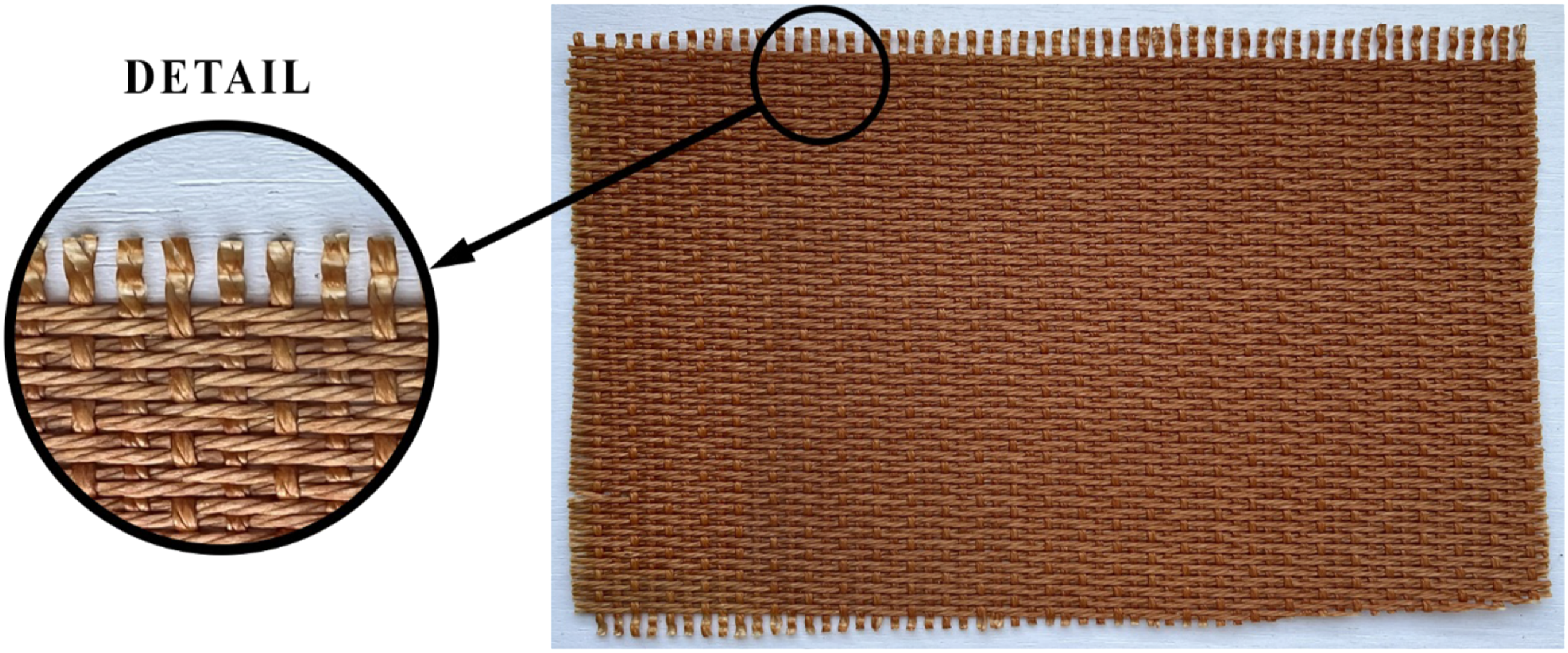
Weaving takes place in special weaving machines adapted for technical fabric production. The warp threads are evenly distributed in the prescribed length and width, thanks to weaving. Longitudinal (warp) and transverse (weft) threads cross during weaving. The threads are thus woven perpendicular to each other. The point of contact where the warp and weft thread cross is called the binding point. Crossing the warp and weft threads is called the weave of the fabric.
Technical fabrics are impregnated to improve the cohesion of textile and rubber. The primary characteristic of a textile fabric is its density in the warp and weft, indicated by the number of threads per 10 cm or 1 m in the weft warp. The final textile fabric strength on warp and weft depends on the number of threads and their weight.
Canvas weave
The canvas weave has a very dense binding. Its structure is realized by alternating the binding of the weft and warp-tied point. The weft thread passes (is bound) alternately over the warp and then under the adjacent base thread. The structure ensures an extraordinarily strong binding, preventing the weft and warp from moving against each other, resulting in a strong and rigid fabric.
Twill weave
Twill is a weave of fabric characterized by a set of parallel rows running along the fabric surface from left to right or vice versa. In principle, we distinguish warp twill Figure 5(a)) and weft twill Figure 5(b)). Depending on the row’s direction, left twill or right twill can be determined. Example of the warp and weft Twill structure.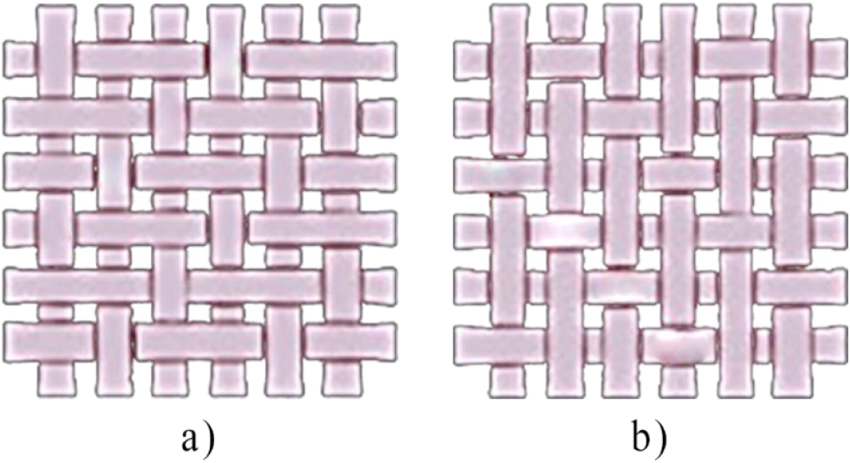
Results
Research specimen characteristic
A 3D model of an experimental specimen was created for the research using the PTC Creo software Parametric 9. The 3D specimen was modeled as a textile imitation. Horizontal fibers were woven with vertical fibers just like actual fabric. This means that in certain specimen areas, vertical fiber was omitted when designing the 3D model to follow the structure as it is in the real fabric specimen. The diameter of horizontal fibers was 2 mm, and vertical fibers was 1.5 mm. The 3D specimen model and a detailed view of the fibers' location can be seen in Figure 6. A 3D model of textile imitation.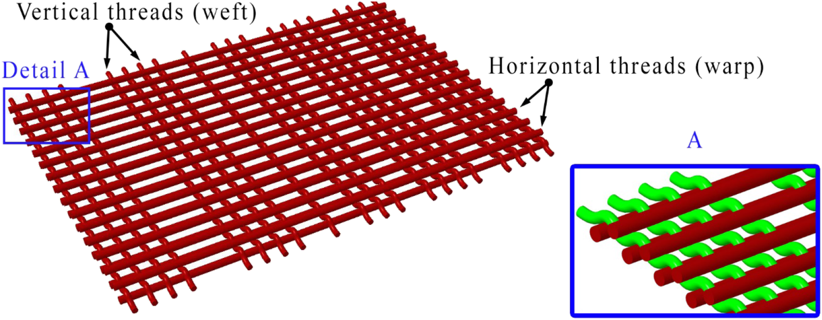
For our research, selective laser sintering (SLS), fused deposition modeling (FDM), and stereolithography (SLA) were used to manufacture several pieces of textile specimens. The experimental specimens were planned to be produced in three distinct positions: • at an angle (45°), • horizontally (XY), • vertically (XZ).
Different material consumption and printing lengths were planned for each position due to a support structure. Figure 7 shows the method of marking three distinct positions in the experimental specimen manufacturing. Method of marking positions during experimental specimens manufacturing (a) at an angle – 45°, (b) horizontally – XY, (c) vertically – XZ.

Fused deposition modeling technology use to create a structure for technical fabric replacement
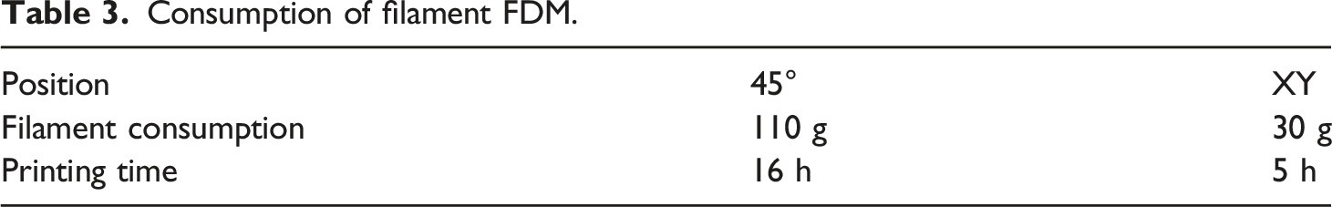
Consumption of filament FDM.

Position of 3D specimen models in the Slicer (a) at an angle – 45°, (b) horizontally – XY.
With this technology, the specimen was printed in only one position (XY), as the printing at an angle of 45° would require several supports. Thus, specimen production using this technology would be unprofitable. Vertical printing by this technology was not realized due to the “fusion” of FlexFill 92A material; therefore, in Figure 9, the experimental specimen only printed horizontally can be seen. The specimen was printed under the melting temperature of 230°C, preheating the substrate to 60°C, and the filament diameter was 2.85 mm. The visual specimen quality is the lowest level compared to SLS and SLA technologies. The specimen features shrunken material at specific points (Figure 9), which cannot be removed without damaging the specimen’s structure and the thin fibers that occur when the printing head moves and the material solidifies quickly. FDM technology experimental specimen.
Selective laser sintering technology use to create a structure for technical fabric replacement
A 3D printer, EOS P396, was used to produce specimens with this technology, with a laser with a maximum rated power of 70 W. The printer’s chamber size is 340 x 340 x 620 mm, and the scanning speed is up to 6 m.s−1. The material used to produce the specimen was EOS TPU 1301 powder, mixed in a 50:50 ratio with a similar powder type already used. The ratio for integrating new and used powder is called the refresh factor, which the manufacturer recommends. This type of powder guarantees flexibility and good shock absorption. The hardness of the resulting print is, according to SHORE, 86A. A significant advantage of this technology is that no support structures need to be used when manufacturing products, mainly because no significant internal stresses during printing occur, and the powder is as light as self-supporting. During one printing job, the experimental specimens were made in three positions (45°, XY, and XZ). Due to the absence of support structures, the printing volume is the same for all specimens. With this technology, the specimen was made in all three positions. Figure 10(a)) shows the position of 3D specimen models on the base, while Figure 10(b)) shows the experimental specimens already made by SLS technology in all three positions. (a) Position of 3D specimen models on the base, (b) produced experimental specimens in all three positions.
Although the manufactured specimens shown in Figure 11 look alike, the shape or orientation of their horizontal fibers (warps) differ for each specimen. The elasticity of specimens produced in three distinct positions is remarkably similar to the touch. The most flexible is the specimen made horizontally (XY). The specimens printed vertically (XZ) and at an angle (45°) have undetectable elasticity. In Figure 11, a different orientation of the horizontal fibers (warps) can be seen in specimens produced in distinct positions, resulting in additional flexibility and tensile strength. Orientation of horizontal fibers (warps) in positions (a) 45°, (b) XY, (c) XZ.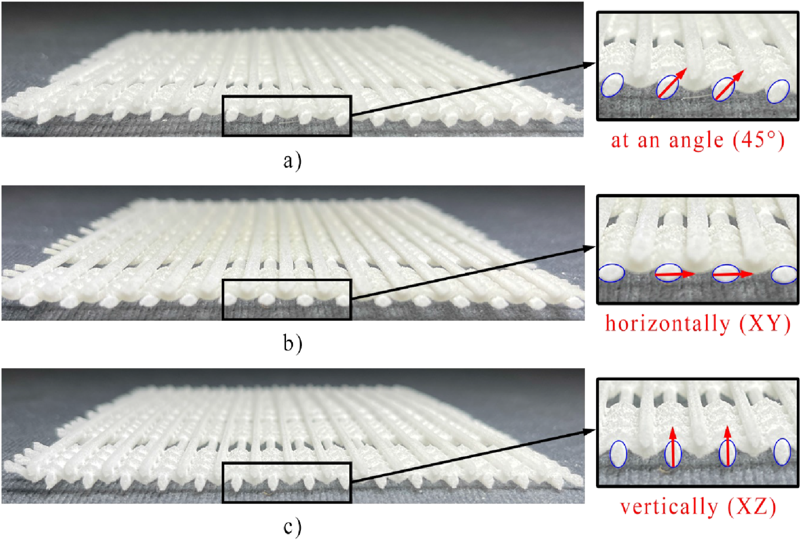
Stereolithography technology use to create a structure for technical fabric replacement
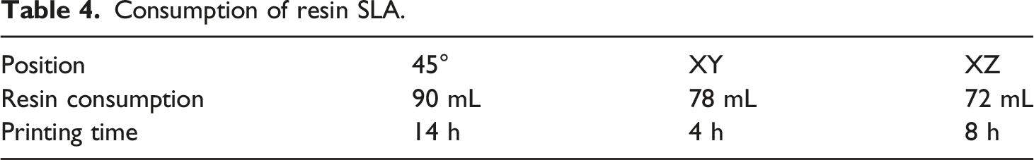
Consumption of resin SLA.
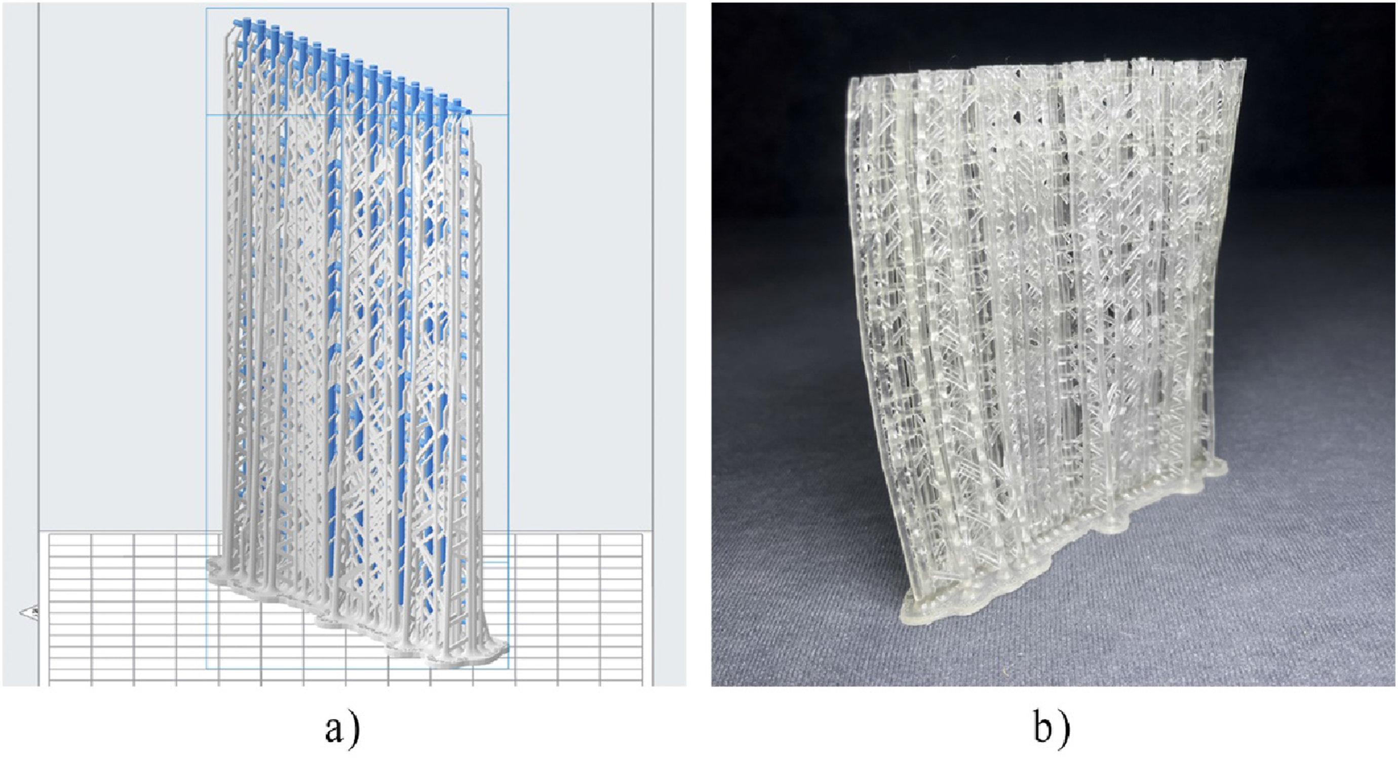
Figures 12–14 show the position of 3D models of experimental specimens with support structures on the Slicer’s base and real-made experimental specimens from which the support structures need to be manually removed. In the mentioned figures, the textile model is indicated in blue. (a) Experimental specimen – 45° a) positioned on the Slicer’s base, b) produced by SLA technology. (a) Experimental specimen – (XY) a) positioned on the Slicer’s base, b) produced by SLA technology. (a) Experimental specimen – (XZ) a) positioned on the Slicer’s base, b) produced by SLA technology.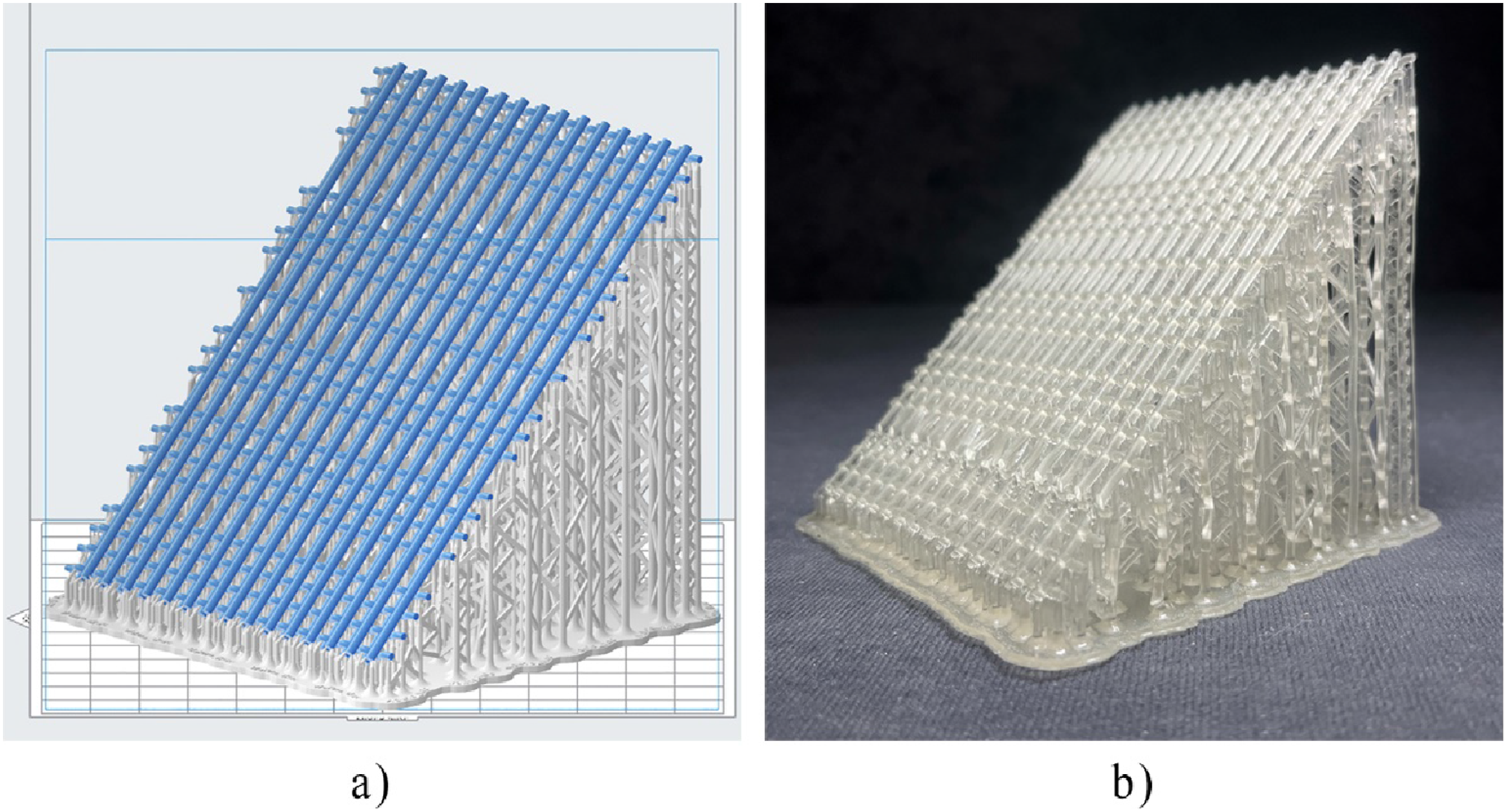

After manufacturing experimental specimens, the support structures needed to manufacture them had to be removed. The easiest was the removal in the specimen printed vertically; see Figure 15(c)) since the support structure was symmetrical to the specimen’s structure. That is why the output, when printing vertically, was the best for this technology. Removing material was impossible in the specimen printed horizontally; thus, the support structure remained unremoved, see Figure 15(b)). The specimen printed at an angle of 45°, shown in Figure 15(a)), was damaged during the support structure’s removal, mainly because of its density. Experimental specimens produced by SLA technology after removal of support structures a) 45°, b) XY, c) XZ.
Printing parameters.

Conclusions
Additive technologies, in terms of hardware and used material, are at the level that opens up new possibilities for their use in production. These areas also include structural components for rubber-textile conveyor belts’ production, specifically their carcass. This field has not been considered in additive manufacturing until now, as the size of the produced specimens has limited production. However, when continuous 3D printing began to be used, conditions were created to research and verify the possibility of manufacturing the carcass of the rubber-textile conveyor belts. The research must be gradual and systematic to confirm or refute the production possibility and feasibility hypothesis. If the result is positive, a significant change can occur and be reflected in replacing existing technology.
Within the paper we present, the research was carried out, the objective of which was: • To confirm or refute the hypothesis that 3D printing can produce a structure replacing industrial textiles in the production of rubber textile conveyor belts. The hypothesis was confirmed because we could make the desired structure. • To produce a flexible belt structure that is as similar as possible to the textile. The application was confirmed thanks to the SLA method, which allows the printed fabric to behave like a production textile during bending. • Analyze the most suitable methods and materials for 3D-printed belts. This task is fulfilled by the choice of SLS technology for producing flexible structures that will replace the carcass of the rubber-textile conveyor belts.
Using additive technologies to create structures that would replace technical fabric is not new. The novelty presented in the paper is in the replacement of industrial textiles in the rubber-textile conveyor belts. Its result will be a structural change in the internal conveyor belt composition, changing the rubber-textile conveyor belt production concept. Current production technology will have to be changed, thus implying a pre-condition for mechanical properties improvement in the conveyor belts. When researching available sources, we found no information that would present research focused like this in the past. The inspiration for our study was drawn from information on the development of additive technologies used in textile materials. The mechanical properties of the created structures will be investigated in detail in the ongoing research. The production technology modification aims to produce a conveyor belt prototype in which the designed structure would replace the industrial textile.
The paper only deals with the application and technological possibilities that have been confirmed, but another part of the research on mass production and print quality is underway. Print quality can be checked by CT tomography, optical microscope, tensile tests in one rod of 3D printed textile, and load predictions. In the next phase of our research, we will study the manufactured structure’s material and strength characteristics and compare them with the industrial textiles used so far.
The presented research result is an introduction to a long-term research project: a new conveyor belt’s structural design, its production technology, and a produced conveyor belt prototype. As a result, the research will continue to measure specimens’ mechanical properties, their mutual comparison, and a comparison with classic industrial textiles. At the same time, long-term monitoring in the form of experimental measurements will be used on testing rigs to obtain a wide range of information to achieve the project objective.
The obtained results have great application potential. In the future, it is possible to implement them in the production of classic conveyor belts. With their help, production can change significantly and become more efficient and of higher quality. However, the assumption needs to be confirmed by further research. Another possibility of applying the presented results is using created structures to improve rubber-textile conveyor belt quality when the designed structure can increase resistance, e.g., against puncture damage. The other possibility of using the knowledge is to develop structures that generate internal forces necessary to unfold the rubber-textile belts in the pipe conveyors. At the same time, the research results advance the possibilities of additive technologies application to an entirely new field (industrial textiles) and help the development and use of continuous 3D printing, with its deployment potential in actual industrial production. Finally, yet importantly, the knowledge obtained from the research can be applied to conveyor belt modularity.
Footnotes
Declaration of conflicting interests
The author(s) declared no potential conflicts of interest with respect to the research, authorship, and/or publication of this article.
Funding
The author(s) disclosed receipt of the following financial support for the research, authorship, and/or publication of this article: This work is a part of projects VEGA 1/0674/24, VEGA 1/0101/22, KEGA 005TUKE-4/2022, KEGA 018TUKE-4/2022, APVV- 21-0195, SP2023/088.