
Abstract
Fabric/unsaturated polyester composites have garnered significant attention due to their lightweight properties and superior mechanical characteristics. Despite these advantages, the strength of joints within these composites remains a crucial aspect requiring thorough investigation. This paper presents a study focused on comprehending the factors that influence joint strength in fabric/polymer composites, emphasizing the importance of effective load transfer and robust adhesion within the fabric/polymer matrix. The objective is to minimize stress concentration and enhance load distribution within the joint. The failure mechanism involves a combination of Bearing Failure and shear-out failure, particularly in single-fabric layer composites. The study establishes a linear relationship between composite bending stiffness and the enforcement fabric’s flexural rigidity. A comparison of tensile properties across various joining methods, such as bolts, adhesive bonding, and tongue grooves, reveals that bolt joints exhibit the highest strength and elongation, followed by tongue groove joints. Notably, bolt joints demonstrate elevated toughness, efficiency, and stiffness in samples of two-layer twill fabric when the twill lines are oriented perpendicular to each other. Under these conditions, joint properties are measured at 0.89%, 14804.65 Nm, and 20.46 J, respectively. Increased fabric flexural rigidity yields advantages in terms of load distribution, load transfer efficiency, and dimensional stability. This study deepens the understanding of factors influencing joint strength, contributing valuable insights for the development of optimized joint designs and manufacturing processes. These advancements aim to enhance the performance and reliability of fabric/unsaturated polyester composites in applications requiring high strength and structural integrity.
Introduction
Composite materials are widely used in aerospace, automotive, marine, and other industries. Joining techniques play a pivotal role in the successful implementation of composite materials in these applications, ensuring they meet performance and safety requirements.1–4
Fabric polymer composites have emerged as one of the most versatile materials for numerous industrial applications. The unique combination of fibers and polymer matrix allows for tailored mechanical properties, enabling engineers to optimize the material for specific requirements. However, the strength of joints connecting different components is a critical aspect of ensuring the overall integrity and reliability of these composites. Composite materials, such as fabric-reinforced polymers, offer several advantages over traditional materials like metals, including high strength-to-weight ratio, corrosion resistance, and design flexibility.5–7
The use of plant waste as reinforcement for composite materials. The creeper plant’s yard cutting was used for fiber extraction and treated with an alkali solution. The fibers were milled into powder and used as reinforcement in composites. The mechanical properties of these composites were investigated, finding that filler-reinforced composites had higher strength and improved modulus. 8
The combination of disparate materials possessing dissimilar property ranges entails a lucid assignment allotment of the constituents while facilitating an optimized utilization of material characteristics. Nonetheless, the conjoining of composite components poses a challenge for manufacturers, as they must ensure an equitable load transmission of the fibers. One pivotal aspect is the selection of the most fitting conjoining technique, to entirely exploit the advantages of composite-metal constructions sustainably. In this regard, the economic feasibility of the manufacturing process is crucial, as well as the requisite mechanical strength of the joint. Different concepts are employed for the joining of thermosetting composite and metallic components, namely adhesive bonding, mechanical fastening, or a hybrid of these methods. The choice of a suitable joining concept primarily hinges on the geometrical configuration of the components. These joint types find widespread application in industry.9–14 The possibility of fully exploring the properties of different materials in the same structure instead of relying on only one strong material, or creating material reinforcement of critical areas, opens up a range of new structural concepts. 15
The weakest point of a composite structure is typically the joint, and it plays a decisive role in determining structural efficiency. The most commonly employed technique for mechanical joining is the bolted joining of composite and metal elements. However, the bolted joining of composite materials entails several drawbacks, primarily caused by the requisite of drilling holes. The drilling process interferes with the continuity of the fibers, resulting in reduced load-carrying capacity and damages such as delamination, fiber pull-out, and micro buckling. Thus, other mechanical joining methods have been developed, some of which were designed specifically to join composite to metals.4,10,15,16
The utilization of adhesives is on the rise in the realm of manufacturing owing to numerous benefits in comparison to alternative methods of joining. Joining technologies and, consequently, adhesives play a crucial role in composites. Adhesively bonded joints possess several advantages, including even distribution of stress, design adaptability, and ease of construction. Structural adhesives are implemented instead of conventional mechanical fasteners, such as bolts and welds, as they are substantially lighter and disperse stresses more evenly throughout the joints. Furthermore, the adhesive bonding technique allows structural components with disparate mechanical and thermal properties, such as composites and metals, to be conjoined; hence, it enhances the overall structural integrity.17,18 Identifying the causes of bond failures can be challenging and requires consideration of multiple factors. Choosing the appropriate adhesive for different materials in adhesive joints is complicated due to the lack of a universal adhesive. Etching and degreasing are vital for achieving high joining strength in metallic adherents during bonding. 19
The existing literature on fabric polymer composites primarily focuses on the mechanical properties of the composite materials themselves, with relatively limited studies devoted to joint strength analysis.
This paper aims to comprehensively investigate the strength of joints in fabric polymer composites, offering valuable insights for enhancing their mechanical performance in practical applications and applying different types of joining methods.
Material and method
The investigation of joint strength in fabric polymer composites highlights the importance of understanding stress distribution and failure mechanisms. A set of standardized joint configurations was designed. The experimental and numerical results complement each other, providing a comprehensive understanding of joint behavior.
Fabric specifications
Specifications of woven fabric samples.

aStandard deviation.
Mechanical properties of fabrics.

aStandard deviation.
Fabric polymer composite samples preparation
The hand lay-up technique was used to create composite samples, and a release polymer was sprayed on top. Low-viscosity polymeric thermosetting substance (unsaturated polyester) was used as the matrix material. The matrix comprises two chemical elements. The ratio for blending these components is 100 parts of the base (unsaturated polyester) to one part of the hardener (MEKP, or methyl ethyl ketone peroxide). The pressure was applied to the composite to give it the desired shape during the consolidation stage of the liquid composite molding process for 2D woven fabric. The composite can attain its final fiber volume fraction during this phase. To decrease their volume, the strands were compressed. The fabric’s structure and the compactness of the yarns determine the final thickness. 24 Composite samples of different fiber volume fractions and the number of laminates were prepared.
The consistency of the sample quality and volume fraction in the composite material was ensured during the hand layup technique through meticulous attention to the manufacturing process. Quality control measures were implemented at each stage, including precise material weighing, uniform resin application, and careful layering of fabric to maintain consistent fiber orientation. Additionally, a standardized and controlled environment was maintained to regulate factors influencing the curing process. Regular inspections and adherence to established procedures were integral in achieving uniformity across samples. The author acknowledges the importance of these measures in maintaining the reliability and reproducibility of the experimental results.
In the case of different types of fibers and different fiber densities of the warp or weft yarns, the value of the fabric volume would be:
The fabric-reinforced polymer composite samples specifications.

aStandard deviation.
Composite sample tests
All the composite samples were tested for tensile strength and 4-point flexure test according to ASTM D3039, 25 and ASTM D7264. 26
Tensile strength
According to ASTM D3039, 25 a uniaxial load was applied through both ends of the specimen during the tensile test on the Mecmesin (MultiTest 5 - xt) testing apparatus with a load capacity of 5 kN and a loading rate of 1 mm/minute. Overall sample dimensions were 200 mm long and 25 mm wide.
There are two different types of samples for each composite sample that were tested:
One solid sample and the other sample with a 6 mm hole diameter in the middle of the sample.
Four-point flexure test
The Mecmesin testing equipment (MultiTest 5 - xt) with a load capacity of 5 KN and a displacement speed of 1 mm/minute was used to conduct the four-point flexure test (ASTM D7264 standards),
26
as shown in Figure 1. The specimens were 25 mm wide and 200 mm long overall. Bending force readings were taken at deflection 20 mm. Results from the testing of five samples have been reported on average. Flexural strength tester.
The strength of composite sample joints
Selecting an appropriate joint configuration is based on the specific application and loading conditions. It is used in common joint types for composite materials including bolted joints, bonded joints, and Tongue and groove joints.
Single-bolt, double-lab joint configuration
To conduct double-lap bolted joint tests, the ASTM D5961
27
testing standard was employed. The bolt’s diameter (D) measured 6 mm. The edge distance-to-diameter ratio (𝐸/𝐷) equated to 3, and the width-to-diameter ratio (𝑊/𝐷) was maintained at six for all samples, as depicted in Figure 2. This figure illustrates the experimental setup and test fixture used for the double-lap bolted connections. Single-bolt, double-lab joint configuration of composite plate (a) Sample dimensions, (b) Testing attachment.
The calculation for bearing stress is outlined as follows:
Here, 𝐹 represents the force applied, and t signifies the thickness of the sample. D denotes the bolt diameter.
It’s customary to observe a fall in the load profile at the onset of bearing failure. This particular data point often characterizes the bearing strength. Conversely, at the peak load-carrying capacity of the specimen, the measured stress is typically denoted as the ultimate strength. 28
The performance of composite bolted joint with single bolt, double-lab joint as in composite samples with fabrics No. 4, 5, 6, and 13 of 1L(one layer). Besides, the newly constructed twill 2/2 fabric composite sample consists of two fabric polymer composite layers samples. In the first, the twill directions are in the same direction, and the second construction, the twill directions are in the opposite direction to each other. At least three samples were tested with each configuration.
Bonded joints (adhesive bonding) composite
The bonded joint represented in Figure 3 with fabric composite No. 6 with 1-layer fabric polymer composite using two chemical elements in the matrix. 100 base (unsaturated polyester) to 1 hardener (MEKP, or methyl ethyl ketone peroxide) is the ratio for combining the two components. Bonded joints composite testing attachment.
Tongue and groove joint composite
When the two composite ends are fitted together, the tongue is inserted into the groove, creating a tight, interlocking connection. The last joint is evident in Figure 4 with fabric-polymer composite No.6 with a single fabric layer. The tongue and groove design helps with aligning the boards during assembly, reducing the chances of misalignment. Tongue and groove joint testing attachment.
Results and discussions
The primary goal of joining composite plates is to ensure the structural integrity of the final product. Properly joined composite plates can distribute loads evenly, improving the overall strength and performance of the composite structure. Joining the fabric/polymer composite plates is important as it helps to increase the overall strength and durability of the composite structure. Proper joining techniques can also prevent delamination and improve the structural integrity of the composite material. There are several methods for joining fabric/polymer composite plates, including adhesive bonding, and mechanical fastening. Each method has its advantages and disadvantages, and the choice of method will depend on the specific application requirements. Joining fabric/polymer composite plates is a critical aspect of the manufacturing and design of composite structures. However, effectively joining these materials requires careful consideration due to their unique properties. The important requirements of proper joining techniques: 1. Composite materials typically display anisotropic characteristics, implying that their properties differ based on direction. Therefore, while joining composite plates, it becomes crucial to guarantee effective load transfer at the joint to uphold structural efficiency under diverse loading conditions. The strength of the joint necessitates careful assessment. 2. Composite materials grant designers increased flexibility in shaping components. Nonetheless, during the joining process, it is of utmost importance to meticulously manage the process to preserve the intended shape and structural integrity of the end product. Special attention should be given to joint bending deflection.
Mechanical properties of composite samples
Impact of hole drilling on the tensile strength of fabric-polymer composite specimens
The fastening efficiency and excellence rely on the drilled hole quality. Producing error-free precise holes is wanted to ensure high joint strength during assembling the materials by riveting or bolting. Nevertheless, undesirable damages during machining are prone to delamination, cracking, fiber pull-out, fiber fuzzing, matrix chipping, and de-bonding. Optimum joint proportions have evolved from invariant relationships between structural tension, shear, and bearing strengths. Because of the essential differences in properties caused by the anisotropy and inhomogeneity of composites, design policies that evolved for metal joints cannot be applied directly to composites.
29
Figure 5-a,a1, b,b1, c,c1 shows the change of the strength, strain, and modulus of elasticity of samples with and without the hole in the middle length of the sample. The change of the strength, strain, and modulus of elasticity of samples with and without the hole at the middle length of the sample. (a and a1) Breaking load. (b and b1) Breaking strain. (c and c1) Modulus of elasticity.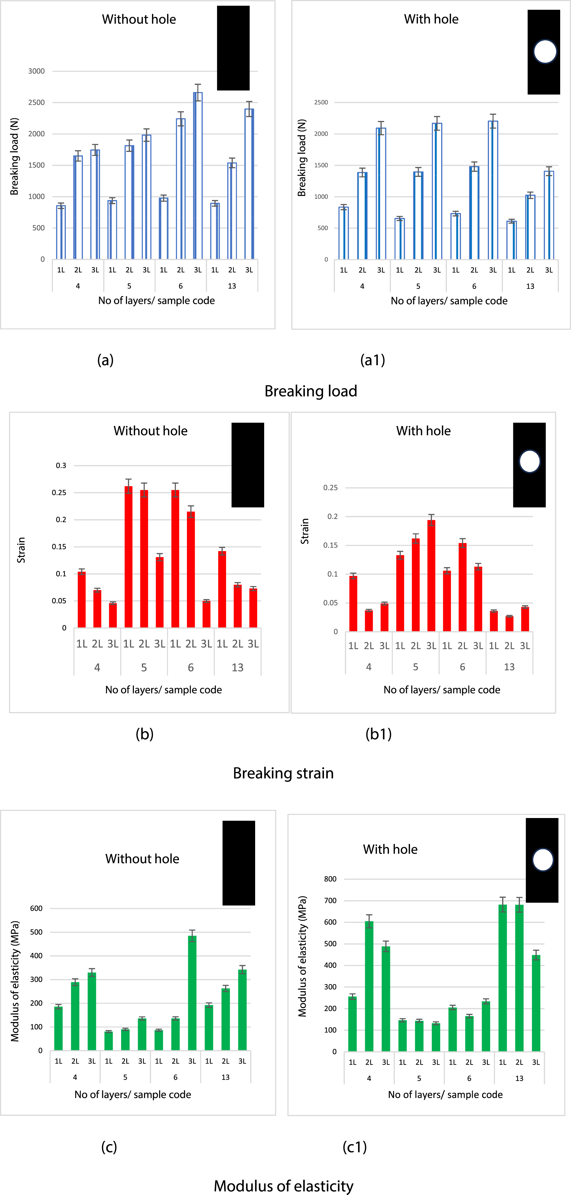
Cutting a hole in a fabric can have several effects on its mechanical properties, depending on the type of fabric, the size and shape of the hole, and the specific application or use case. Cutting a hole in a fabric will reduce its overall tensile strength. The presence of a hole creates a stress concentration point, making it more likely for the fabric to tear or fail when subjected to tension. The fabric can also reduce its stiffness, making it less rigid and more flexible in the vicinity of the hole. The impact of cutting a hole in the fabric will depend on the fabric’s material and weave pattern. 30
The toughness is defined as the area under the entire load–elongation curve. The toughness quantifies the potential of samples to absorb energy under tensile loading. Figure 6 shows the value of the toughness of the composite sample when a hole was drilled in the middle of the sample compared to the normal sample. Mechanical properties of the different samples before and after drilling.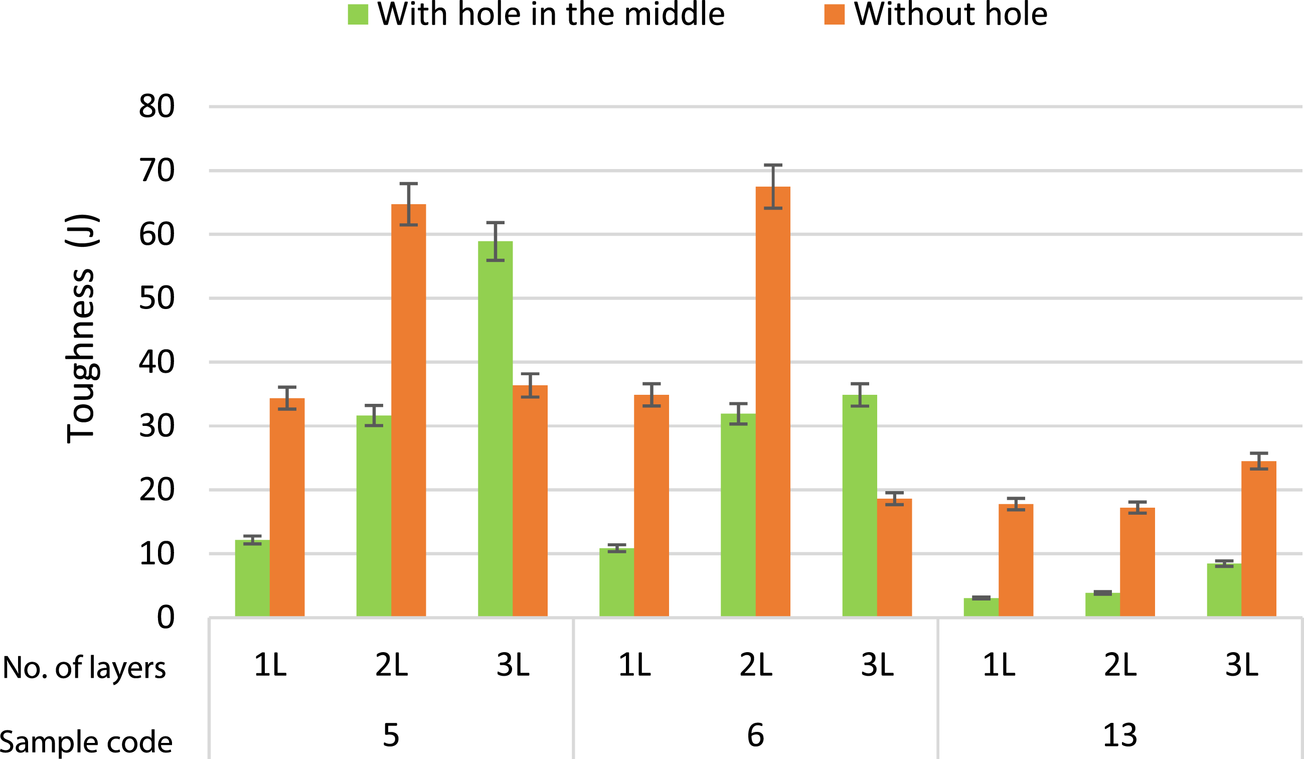
Increasing the number of fabric layers in fabric-reinforced polymeric composites can have several effects on its mechanical properties, which refers to the composite’s ability to resist fracture and deformation under applied stress, as well as its structure.
The specific impact of adding more fabric layers will depend on various factors, such as the type of fabric, the polymer matrix properties, and the manufacturing process of the composite. From Figures 5 and 6 it can be revealed that • Increasing the number of fabric layers can enhance the overall strength of the composite material. The fabric layers act as reinforcing elements, helping to distribute and bear the applied load. This effect is especially noticeable when the fabric has a high tensile strength (comparing samples No. 4 and No. 13 Figure a). • The multiple fabric layers provide resistance to crack propagation, contributing to the composite’s overall strength. Cracks that may initiate in the matrix are bridged or halted by the fibers, preventing them from propagating and leading to failure. • More fabric layers typically lead to increasing layers providing resistance to crack propagation, contributing to the composite’s overall strength. Cracks that may initiate in the matrix are bridged or halted by the fibers, preventing them from propagating and leading to failure. Stiffness or rigidity of the composite, the value of Young’s modulus increases as the number of layers increases, Figure 5, c1. • Enhanced composite toughness: Multiple fabric layers can create a composite with higher toughness, Figure 6. It has to be mentioned that in the multi-layer interesting paths within the composite. When a crack propagates through the material, it may be impeded or deflected at the interfaces between fabric layers, which can improve the composite’s fracture toughness. • With more fabric layers, there are additional opportunities for crack bridging to occur. Crack bridging refers to the process where cracks in the matrix are partially filled or held together by the fabric, transferring stress, and preventing further crack propagation thus enhancing resistance to delamination.
Drilling a fabric/polymer composite can have both positive and negative effects on its mechanical properties, depending on various factors such as drilling parameters, composite material properties, and fabric specifications. Drilling introduces holes in the composite, which can act as stress concentrators and reduce its overall strength. The presence of holes may lead to premature failure under mechanical loading, especially in tension or bending. 15 Figure 5- a1, b1, c1, d1 shows the effect of the drilled hole in the composite on the mechanical properties.
Drilled holes can reduce the fracture toughness of the composite material, making it more sensitive to crack propagation and delamination. The introduction of holes can decrease the stiffness of the composite, especially in the area of the holes. This can affect the overall structural integrity and performance of the composite. The drilling force varies as the drill bit passes through the composite thickness. There is a possibility of delamination of the composite depending on the value of interfacial shear stress between layers. This is besides the several factors that result from improper drillings, such as manufacturing defects including delamination, resin starved areas, resin-rich areas, air bubbles, wrinkles, and voids,31–33 which may result in. 1-Delamination is the separation of layers within the composite material, which severely degrades the mechanical properties of the composite. 2- During the drilling process, fibers in the composite may experience damage, such as cutting or breaking, which can weaken the material and reduce its load-carrying capacity.34,35 3- Drilling can introduce residual stresses around the drilled hole, which might lead to premature failure or affect the long-term durability of the composite component.
36
4- The fabric of high fabric flexural rigidity will form stiffer laminate that doesn’t deform much under the effect of thrust force during drilling and an increase in the possibility of peel-up delamination is expected.
34
The occurrence of the above defects will depend on the type of fiber and its mechanical properties, fabric specification, the number of layers, and the stiffness of the final composite.
To understand the effect of fabric specifications on the flexural bending results of a particular composite, using different fabric types, weights, and other relevant parameters while keeping the matrix material and processing conditions constant. By comparing the results of the four-point flexure bending results of the different composite constructions are shown in Figure 7. Bending stiffness of the various composites as a function of number of fabric layers.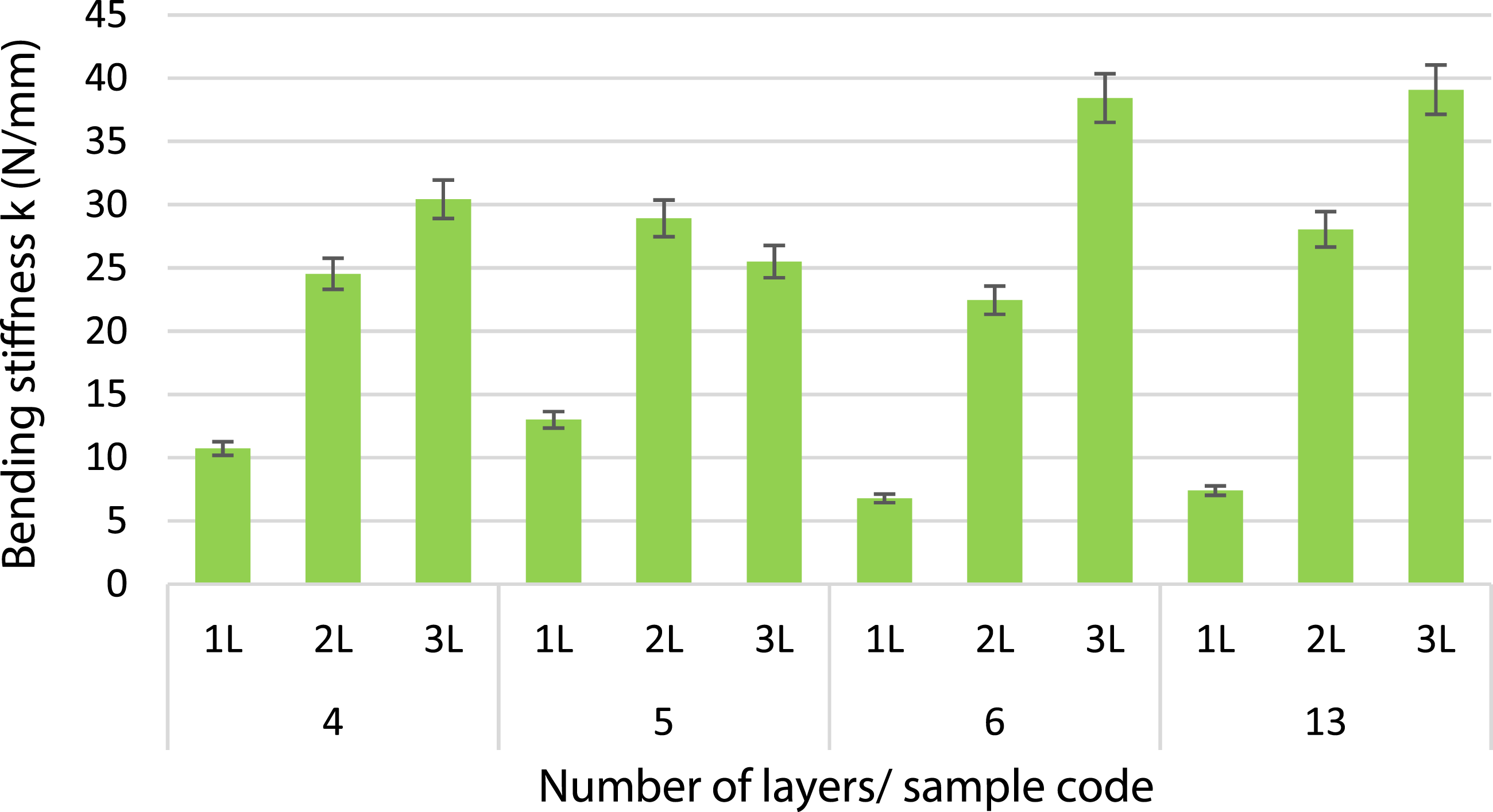
The analysis of the results identified that sample No. 6 has the highest bending stiffness. The increase in the number of laminates increases proportionally the bending stiffness. The weave pattern (e.g., plain weave, twill weave, basket weave) that is, yarn distribution in the composite and, consequently, its mechanical properties of the composite. The weight of the fabric affects the amount of reinforcement in the composite fiber volume fraction. Generally, higher fabric weight leads to increased stiffness and strength, comparing samples No. 5 and No. 6.
Bolted joint failure analysis
There are three ways for composite bolted joints to fail, net tension, shear-out, and bearing modes. Combinations of these failure modes (mixed mode) may be possible.35,37
Mechanical fasteners, such as bolts, rivets, or screws, are used to join the fabric and polymer components together. Holes are typically drilled into the fabric layers, and fasteners are inserted through these holes. The advantages are it allows for disassembly and reassembly, provides higher joint strength, and is suitable for applications with dynamic loads. Its disadvantages are that introduces stress concentrations at fastener locations, may require additional reinforcement around fastener holes, and adds weight and complexity to the structure.
The bolted joint is one type of mechanical fastening method, which is preferred due to low cost, and free surface treatment.38,39
The joint failure mode may be bearing failure, the contact stresses between the bolt and the composite material exceed the bearing strength of the composite, which can lead to deformation and damage around the bolt hole, reducing the integrity of the joint.
In some cases, the joint suffers pull-through failure when the bolt pulls through the composite material due to insufficient bearing strength, this failure mode is more likely to occur in thin composite laminates or when the hole diameter is too large relative to the bolt diameter. Finally, the shear-out failure is a result of the composite material shearing off around the bolt hole due to excessive shear stresses.
Before investigating the failure behavior of the bolt joint, it is essential to assess the deformation of composite samples featuring a hole subjected to tension.
The shapes of the failure of the different composite samples with holes.

The analysis of the shape of sample joint failure shows that in most cases the samples failed under bearing failure except twill samples 4, and 5.
The failure is a combination of both bearing failure and shear-out failure, especially for one fabric layer composite. The failure shapes of the various composite samples are displayed in Table 4. Every sample has a failure that occurs in the center of a hole. The composite material may sustain damage, such as broken fibers, which weakens the substance and lowers its bearing capacity to support loads. Due to the absorption of polymers during manufacture, samples made of pure cotton failed with hairy edges while samples made of polyester gave smooth edges or maybe had fewer broken yarns. 15
Bolt joint failure analysis
As shown in Figure 8, bolt joints in a fabric polymer composite, there are several potential failure types to consider. Here are some common failure modes that can occur in such bolt joints.40–43 Failure modes of fabric polymer composite: (a) shear-out, (b) net-tension, (c) Cleavage, (d) transverse splitting, (e) bearing.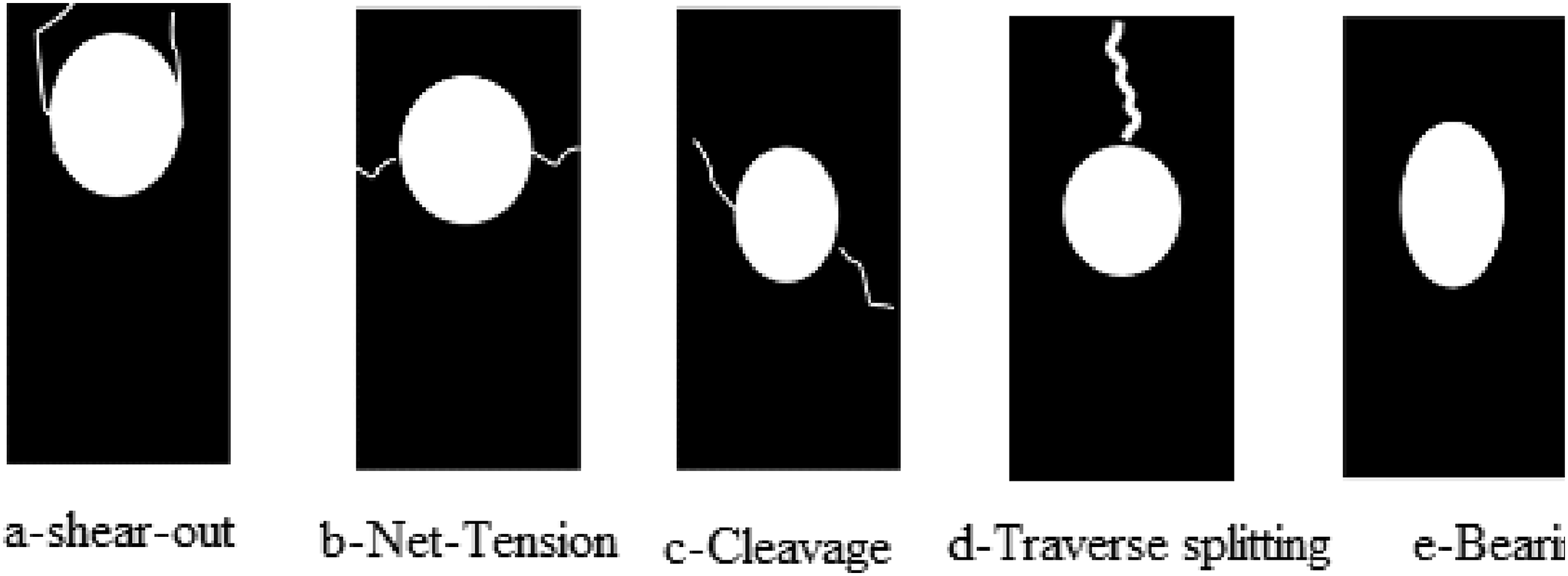
Shear Failure: This occurs when the load applied to the bolt joint exceeds the shear strength of the composite material. Shear failure is characterized by the material splitting or breaking along the plane perpendicular to the axis of the bolt.
Bearing Failure: Bearing failure happens when the compressive load applied to the bolt joint causes the composite material to deform or crush around the hole where the bolt is inserted. This type of failure is influenced by the bearing strength of the material.
Tensile Failure: Tensile failure can occur if the composite material in the vicinity of the bolt-hole experiences excessive tensile stresses that exceed its tensile strength. This might lead to cracking or tearing of the material.
Transverse splitting: Applying excessive load or stress on the bolt can cause it to fail by transverse splitting.
It’s important to note that the specific failure mode in a bolted joint of a fabric polymer composite protection system can be influenced by factors such as the composite material’s properties, the design of the joint, the applied loads, and environmental conditions. To ensure the reliability and longevity of bolt joints in such systems, it’s essential to consider these factors during design, material selection, and installation.
The load-elongation analysis of bolt joint failures in fabric polymer composites sheds light on the mechanical response of joints to applied loads. This exploration enables a deeper understanding of failure mechanisms and the effect of enforcement fabric properties on the joint breaking load. By subjecting fabric polymer composite bolted joints to controlled loads, this analysis aims to perceive the relationship between the applied load and the subsequent elongation of the joint. This load-elongation curve offers crucial insights into the mechanical response of the joint, indicating the effect of the mechanical properties of the enforced fabric. The theoretical 3-stage model for a single-lap bolted-joint consists of the following stages: 1. Elastic deformation stage: As the joint is loaded, the material experiences elastic deformation. The tension force is also redistributed due to the presence of clearances. 2. Yielding stage: If the load is increased beyond the elastic limit of the material, plastic deformation occurs, and the material enters the yielding stage. 3. Failure stage: If the load continues to increase, the material will eventually fail, and the joint will no longer be able to support the applied load.
Figure 9 shows details of the load-elongation curve for one of the samples, for illustration of the measurements. The force elongation curve of the bolt joint.
The analysis of the curve shows that it consists of several distinct stages. The first stage in the profile shows a linear response, which reflects a pure deformation with no significant damage initiation. A tangent line is considered, and the slope is calculated as bearing stiffness.
Following this stage, a nonlinear relation is developed because of the initiation and development of bearing damage in the laminates up to the ultimate bearing strength.44,45
After its peak value, the stress rapidly decreases with an increase in the strain as a function of the excess propagation in the composite failure modes which consist of matrix cracking, yarn breakage, and composite delamination, and the joint loses bearing capacity.
The failure shapes of the bolt joint.


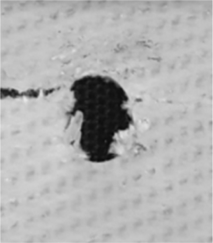


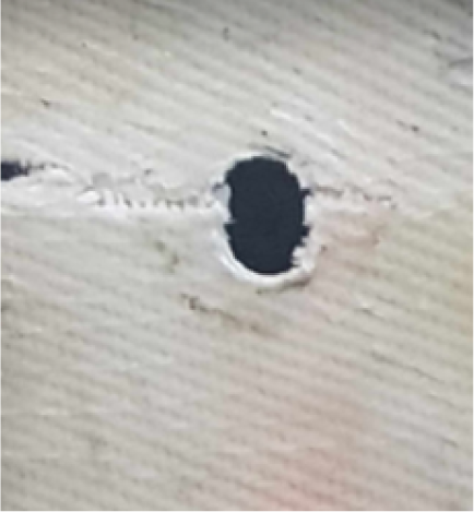


Table 5 gives the possible failure modes linked with composite bolted joints including net-tension, shear-out, and bearing failure. Shear-out and net-tension modes typically manifest suddenly and catastrophically, while bearing failure may gradually develop and sustain some load during damage progression until ultimate failure. The bearing capacity of a bolted joint primarily depends on the contact area between the bolt and hole edge. The progressive nature of bearing failure is associated with the accumulation of local damage at the hole edge, involving intricate and sometimes competing damage mechanisms.
Effect of the twill line on the strength of the bolt joint
In the case of using two fabric polymer composite layers’ samples to form the composite with a twill design as shown in Figure 10, the twill angles can be chosen to be perpendicular to each other. When the twill lines of the two layers in a composite material are perpendicular to each other, it generally results in improved mechanical properties, such as higher failure force. This is because when the layers have perpendicular twill lines, the load-bearing capacity of the composite structure increases due to improved stress distribution. When an external force is applied to the bolt, the load is distributed more evenly between the two layers. This distribution helps prevent the material from failing early, leading to a higher failure force compared to other orientations. In the context of composite materials with perpendicular twill lines, having perpendicular layers can also lead to reduced elongation compared to other orientations. This is because the fibers in the two layers are less likely to slide past each other when they are perpendicular, restricting the ability of the material to stretch. This reduced elongation can be advantageous in terms of maintaining structural integrity and preventing excessive deformation. Figure 10 shows the force-elongation diagrams for the two-layer composite in the case of the twill angle in both layers being the same or perpendicular to each other. Load elongation curve of the bolt joint samples of two twill fabric polymer samples of different fabrics in the same and opposite twill directions.
In all cases, the failure force of the bolt joint is higher when the twill line in the two layers is perpendicular to each other while the elongation is reduced in all cases. For bolt joint limit criteria; such as maximum stress and maximum strain criteria predict the failure load and failure mode by evaluating the stresses in the composite laminate and comparing it separately with the corresponding strengths.
46
Figure 11 shows the value of the tensile joint breaking load and elongation %. The correlation between the tensile joint breaking load and the bending stiffness and toughness of the composites was found to be highly positive (r = 0.97, 0.98 respectively). Bolt Joint tensile breaking load and breaking elongation %, (a) Tensile strength, (b) Tensile elongation.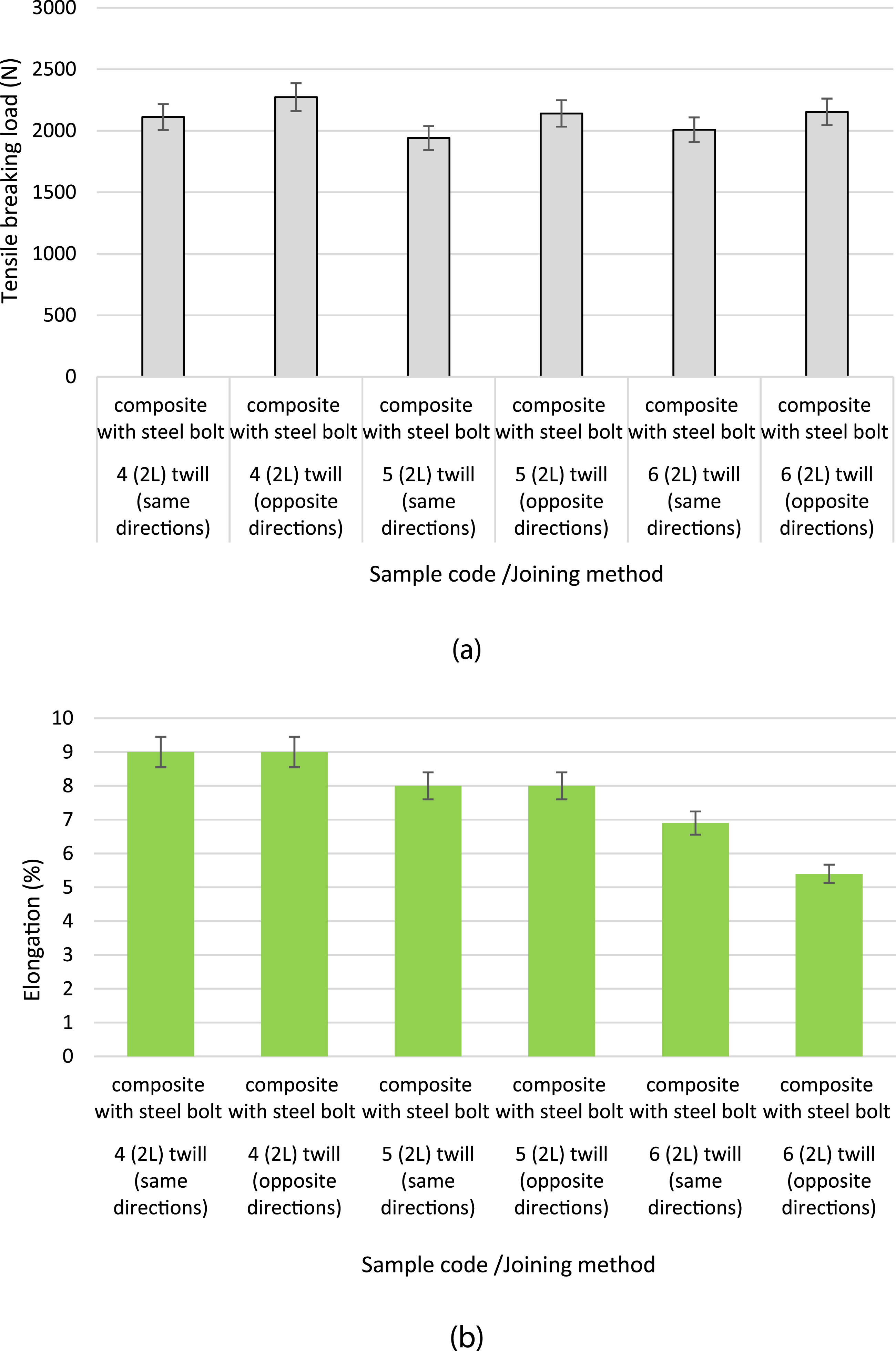
Effect of the fabric flexural rigidity
The failure of the joint may cause different situations depending on the stiffness of the composite which may be bent as shown in Figure 12. Causes the rotation of both composite joints and the bolt. Consequently, the failure of the joint will take different shapes as shown in the given figure. Effect of composite stiffness on joint deformation.
The interaction between fabric flexural rigidity and bolt joint strength of fabric/polymer composites is intricate and reliant on several variables. Increased fabric flexural rigidity typically yields advantages concerning load distribution, load transfer efficiency, and dimensional stability. A fabric with higher flexural rigidity is generally more rigid and less liable to the bending of the formed composite. Figure 13 shows a linear relation between the composite bending stiffness and the enforcement fabric flexural rigidity. Composite bending stiffness versus the enforcement fabric flexural rigidity.
Increased flexural rigidity can strengthen resistance against the deformation induced by bearing stress, strengthening the joint’s load-bearing capacity. The impact of flexural rigidity extends to shear and peel strength within the joint. A composite material with higher rigidity is less susceptible to shear distortion or peel separation at the interface, consequently elevating joint strength. However, flexural rigidity only constitutes one facet of a fabric polymer composite’s comprehensive mechanical behavior. Other factors like tensile strength, modulus, and interfacial bonding with the polymer matrix are also pivotal in determining joint strength.
Figure 14 illustrates the relationship between joint strength and fabric flexural rigidity, confirming the aforementioned analysis. The joint breaking load versus the fabric flexural rigidity.
When incorporated into a bolted joint, this rigidity aids in distributing loads more uniformly across the composite material, preventing localized deformations near the bolt holes. This mitigation of stress concentrations can mitigate the risk of premature failure. Enhanced flexural rigidity can enhance stress transmission between the composite and the bolt, effectively dispersing applied loads amidst the joint components. This contributes to an overall stronger joint.
Figure 15 illustrates a linear relationship between the joint breaking load versus the composite bending stiffness. The joint breaking load versus the composite bending stiffness.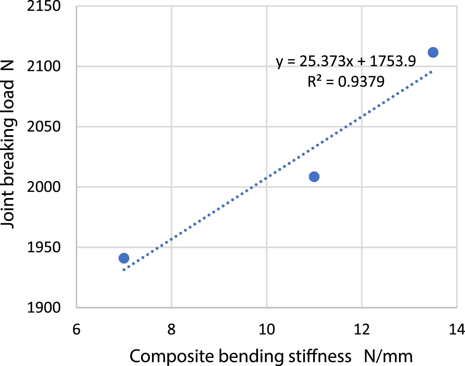
Analysis of factors determining the bolt-composite performance
When determining the effect of the composite enforced fabric on a bolted joint, several factors should be considered:
The material properties of the bolt and the clamped materials play a crucial role in determining the preload force. Factors such as the yield strength, elasticity, and hardness of the materials should be considered. Joint Stiffness: The stiffness of the joint determines how much the clamped materials will deform under the applied preload force. The joint stiffness is influenced by factors such as the thickness, geometry, and material properties of the clamped materials. All the parameters of the fabric properties and specifications were found to affect the joint performance.
Joint toughness
Comparison between the different samples’ joint parameters.

aStandard deviation.
Joint efficiency
Joint efficiency is an integral part of the joint analysis. It can help to optimize the different joint parameters. Bolted joints are a primary means of transferring mechanical loads within composite structures. The efficiency of the results from those joints ensures that loads are evenly distributed across the structure, preventing stress concentrations that could lead to premature failure.
The joint efficiency (η), has been evaluated by using the following equation, and the results are given in Table 6.
The analysis of the results shows that samples that have opposite twill line layers have the highest joint efficiency than the others. Moreover, sample 4 shows the highest value of (η). This could be attributed to the resolution of the vertical load in the direction of the twill lines.
Joint stiffness
Joint stiffness is a crucial factor of structural design since stiffness in bolted composite joints helps maintain the structural integrity of the entire composite structure. It ensures that the components remain securely connected and that the structure can support the intended loads without excessive deformation. Stiff joints distribute applied loads more evenly across the composite components. This is crucial for preventing localized stress concentrations, which can lead to premature failure of the structure.
47

Table 6 gives the effect of the values of the joint stiffness for different samples, which indicates that sample 6 with opposite directions of the twill line gives the highest value of joint stiffness.
The investigation into the properties of joints in fabric polymer composites contributes essential knowledge to the field, facilitating the development of more robust and reliable fabric polymer composite structures for a wide range of applications.
Adhesive bonded and tongue-groove composite joints
There are various jointing methods used to assemble fabric polymer composites. The choice of jointing method depends on factors such as the specific application, required strength, cost considerations, and the properties of the fabric and polymer materials being used.
Adhesive bonded composites joint
Adhesive Bonding involves using adhesives or glues to join the fabric and polymer components together. The adhesive is applied between the fabric layers and the polymer matrix to create a strong bond. Advantages: Provides a continuous and uniform bond, distributes stresses evenly, and can be used with various fabric and polymer combinations. Disadvantages: Requires proper surface preparation and bonding techniques, curing time for adhesives, and the choice of adhesive should match the material properties.
Cohesive failure is the rupture of an adhesively bonded joint, such that the separation is within the adhesive. 48
Figure 16 illustrates the sequence of the failure modes of adhesive bonded joint. The cohesive failure rupture of adhesively bonded joints is a complex phenomenon influenced by various factors. It occurs when the internal strength of the adhesive material is surpassed, resulting in a fracture within the adhesive layer rather than at the adhesive-substrate interface. This is indicated by the separation at the ends of the adhesive bonded area due to shear stress, leading to the propagation of cracks. COH rupture involves crack propagation due to stress concentrations caused by material disparities, geometric irregularities, and defects in the adhesive layer. The cohesive strength of the adhesive, determined by its molecular structure and intermolecular forces, governs its ability to resist crack propagation. Different loading conditions (tensile, shear, peel stresses) have distinct effects on COH rupture: tensile stresses open cracks parallel to the load, shear stresses lead to sliding along crack surfaces, and peel stresses cause separation from the substrate, initiating perpendicular crack propagation. Increasing tension stress reduces adhesive strength until sudden joint separation. This mechanism involves crack initiation, propagation, and eventual fracture within the adhesive due to surpassing its cohesive strength.
49
The sequence of the failure modes of adhesive-bonded joint.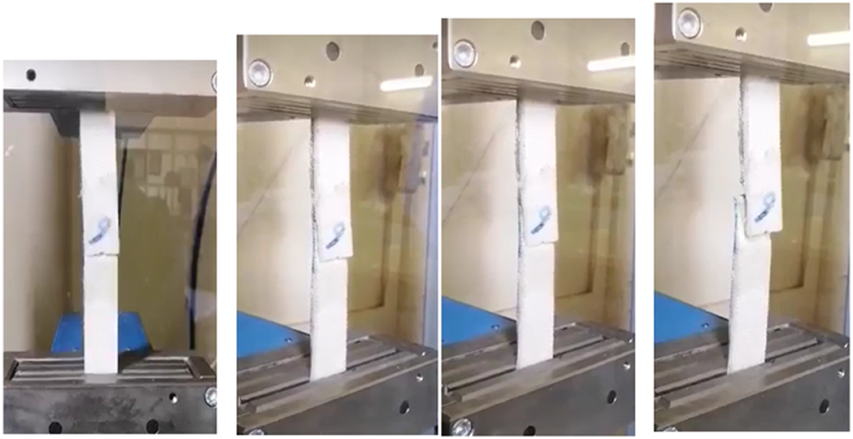
The specific mechanical properties of composite adhesive joints can vary depending on the type of composite materials used, the adhesive selected, the bonding process, and the application requirements. The strength of a joint depends on the bond between the adhesive and the adherents. A strong adhesive-to-adhered bond is essential for effective load transfer and performance of the joint. The maximum tensile load a bonded joint can withstand before failure is defined as the performance of the joint. It is essential to ensure that the adhesive bond can withstand the applied tensile forces without delaminating. This may lead to excess resin buildup, potential delamination issues, and variations in laminate thickness.
Tongue-groove bonded composites joint
Tongue and groove joining is a method used to connect composite materials. This method involves a male (tongue) and female (groove) interlocking system, which creates a strong and secure bond between two adjoining pieces. When compared to other joining methods used in composites, such as adhesive bonding, mechanical fasteners (bolts), tongue and groove has its unique advantages and mechanical properties. In this work, a tongue and grove were cut at the ends of the composite joint and joined together using a suitable polymer, and pressed under a load till the joint was joined together.
The failure mode of the tongue-groove joint
The failure mode of the tongue and groove joint is different from the other methods. Tongue and groove joining provides excellent strength and load transfer capabilities due to the interlocking design. It distributes the applied loads across a larger contact area, reducing stress concentration points and enhancing the joint’s overall strength. Adhesive bonding can also provide high strength, as it creates a continuous bond between surfaces. Adhesive bonding can offer a degree of flexibility, but it may not be as effective in accommodating large movements as tongue and groove joints. The failure mode of a tongue and groove joint can be different from other joining methods due to its unique design and mechanics. The tongue and groove joint primarily relies on an interlocking system to provide strength, which can lead to distinct failure patterns compared to other joining methods such as adhesive bonding or mechanical fasteners.
The tongue and groove joint is characterized by a protruding “tongue” on one component that fits into a corresponding groove on another component. This design creates a secure interlock between the components, enhancing the joint’s strength and stability. The unique features of the tongue and groove joint give rise to distinct failure modes compared to other joining techniques. The interlocking nature of the tongue and groove joint leads to a more even load distribution across the joint interface. This distributed load transmission can lead to failure modes that involve the localized failure of the material within or around the groove or tongue. Stress concentrations can develop at the edges of the groove or tongue, potentially resulting in modes of failure such as crack propagation or splitting along these edges. The interlocking nature of the tongue and groove joint can result in more complex fracture patterns compared to joints with simpler designs. Failure initiation may occur at multiple points within the groove or around the tongue, and these failures can interact with each other, leading to intricate crack propagation paths, Figure 17. The failure stress of a joint is the maximum stress the joint can withstand before experiencing failure. In a tongue and groove joint, the interaction between the geometry of the tongue and the composite material’s bending stiffness plays a crucial role in determining this failure stress. A longer and thicker tongue can provide a greater contact area and distribute loads over a larger region of the groove, potentially reducing stress concentrations and enhancing load-carrying capacity. A higher bending stiffness indicates that the material is less prone to bending under a given load, making it more resistant to deformation, and less stress concentration is expected. The sequence of the failure modes of the tongue and groove joint.
The effectiveness of a tongue and groove joint relies on precise manufacturing and assembly to ensure a snug fit between the tongue and groove components. Any discrepancies in the dimensions or alignment of the tongue and groove can lead to improper load distribution and localized stress concentrations, potentially influencing failure modes.
Figure 17 shows the failure of the tongue and groove which indicates how the composite body gives support to resist the applied load.
Comparison between the different types of joint
A comparison between the tensile properties of the several types of joining methods, bolts, adhesive bonding, and tongue groove is given in Figure 18. Failure of Joint samples: (a) tensile breaking load and (b) elongation %: mechanical fasteners (bolts), adhesive bonding, tongue-groove joining methods.
The analysis of failure in different fastening methods.

Previous research has highlighted the importance of joint strength in the overall structural performance of composite materials. However, more in-depth investigations are necessary to fully understand the factors influencing joint strength and design optimization. Bolted joining is a widely used mechanical method for connecting composite materials, with the drilled hole identified as a structural weak point. The joint’s bearing stress, crucial for overall structural effectiveness, is influenced by various factors related to hole geometry and the mechanical attributes of the composite, which, in turn, are affected by fabric properties. Fabric design plays a pivotal role in determining the bearing strength of a composite bolt joint, crucial for withstanding forces perpendicular to its surface. Factors such as fiber orientation, weave pattern, fiber volume fraction, layer thickness, fiber-polymer bond, and hole size collectively impact joint strength. Proper fiber alignment enhances load transmission efficiency, while weave patterns and parameters like fiber volume fraction and thickness influence load distribution. A strong fiber-polymer bond is essential to prevent delamination and maintain bearing strength. The size and quality of the drilled hole also contribute to the overall bearing strength of the joint. These elements together create a complex interplay that defines the strength of fabric-polymer composite bolted joints.
Conclusion
This paper presents a comprehensive investigation into the strength of joints in fabric polymer composites. The study reveals the influence of joint type, fabric material, and polymer matrix on joint strength. By understanding these factors, engineers can optimize joint design and manufacturing processes to enhance the mechanical performance and reliability of fabric polymer composites in various applications. Composite joining techniques have distinct failure mechanisms. Bolt fasteners are susceptible to stress concentrations, adhesive bonding can fail due to adhesive properties and interfacial adhesion, and tongue and groove joints can experience wear or localized damage based on the fit and relative movement of components. Consequently, The choice of joining technique depends on the specific application requirements, the anticipated loads, and the desired durability of the joint. Cutting a hole in a fabric can have several effects on its mechanical properties, depending on the type of fabric and number of layers. Drilling introduces holes in the fabric/polymer composite, which can act as stress concentrators, and may lead to premature failure under mechanical loading, especially in tension or bending. The strength was found to be reduced by 35% while the toughness was reduced by an average of 50%. For two-layer twill fabric samples, the values of joint toughness, joint efficiency, and joint stiffness are elevated when the twill lines are oriented perpendicular to each other. A strong positive correlation was identified between the tensile joint breaking load and the bending stiffness and toughness of the composites, with correlation coefficients of 0.97 and 0.98, respectively. Bolt joints exhibit increased toughness, efficiency, and stiffness in two-layer twill fabric samples when the twill lines are arranged perpendicular to each other. In this configuration, the joint properties are quantified at 0.89%, 14804.65 Nm, and 20.46 J, respectively.
Footnotes
Declaration of conflicting interests
The author(s) declared no potential conflicts of interest with respect to the research, authorship, and/or publication of this article.
Funding
The author(s) received no financial support for the research, authorship, and/or publication of this article.