
Abstract
A new concept in improving the thermo-oxidative stability of carbon fiber polymer-matrix composites (CFPMCs) by adopting integral reinforced structure was investigated. Specimens of three-dimensional and four-directional braided carbon fiber/epoxy composites (BC) and laminated plain woven carbon fiber/epoxy composites (LC) were subjected to isothermal aging at 90℃, 120℃, and 150℃ in air circulating ovens for various durations up to 13 days. The process resulted in progressive deterioration of the matrix reins and fiber/matrix interfaces, in the form of chain scissions, weight loss, and fiber/matrix debonding, which significantly led to the decrease of the flexural strength. Besides, the flexural properties’ retention rates of BC were higher than those of LC at the same aging conditions due to the difference of the reinforced structures. On the one hand, LC lost more weight than that of BC because the percentage of fiber ends area exposure to air in LC specimen was three times more than that in BC specimen. On the other hand, the BC specimens can resist the flexural load as an integral structure although the resin was damaged and the adhesive force between fiber bundles and resin decreased after thermo-oxidative aging, and no delamination happened like the LC specimens. Therefore, adopting three-dimensional and four-directional braided preform as the reinforcement of CFPMCs is an effective way to improve their thermo-oxidative stability.
Keywords
Introduction
Carbon fiber polymer-matrix composites (CFPMCs), owing to their high specific strength and stiffness, as well as other advantages, are attractive for high temperature applications in aerospace. For instance, the future supersonic transport aircraft which is expected to have a service life of around 80,000 h of supersonic flight with a maximum skin temperature of 120℃ [1–5]; under such conditions oxidation reaction/diffusion phenomena take place within the polymer materials and threaten the integrity of the structures [6,7].
The thermo-oxidative degradation occurs initially at the outer surface of the composite and proceeds inwards via a diffusion mechanism [8–10]. Simultaneously, microcracks may occur due to the mismatches in the coefficients of thermal expansion between the fibers and matrix, as well as the resin shrinkage [11] caused by the thermo-oxidative aging (TOA). These microcracks create additional surface area and diffusion paths, enhancing the rate of degradation [12,13]. The process will be exacerbated when the CFPMCs are exposed to high temperature which is close to or beyond the glass transition temperature (Tg) of their matrix resin [14–16]. This means that the higher Tg of the matrix resin, the higher thermo-oxidative stability (TOS) of the CFPMCs is [17,18].
Many researches have been done to improve the TOS of CFPMCs. Among them, the modification of existing resins and the synthesis of novel heat-resistant resins are the main ways [19–22]. The long-term service temperature has varied from 130℃ of epoxy resin to 426℃ of polyimide resin [23,24]. However, on the one hand, the long-term service temperature of polymer is very difficult to be further improved when it has reached 426℃ of the polyimide resin [25]. On the other hand, the emergence of new advanced aerospace applications (“hot” structures) has given new impetus to develop CFPMCs with higher TOS.
It is generally known that the properties of CFPMCs are not only controlled by the matrix material but also by the reinforced structures. However, the reinforced structures currently used for CFPMCs are mostly the unidirectional and laminated systems. For the conventional laminated composites, the occurrence and the development of microscopic damage (fiber/matrix debonding or microcracks) is prone to induce delamination damage. In contrast, all the braider yarns in three-dimensional (3D) braided preform being offset at different angles between the in-plane and through-thickness directions, which make it possible to produce integral composite structure [26]. The 3D integral braided composites can effectively prevent crack extension and improve delamination resistance [27]. Therefore, the 3D braided preform used as the reinforced structure is expected to improve the TOS of CFPMCs. However, little work has been done on mechanical properties of 3D braided polymer composites after TOA.
The main purpose of this study was to investigate the effect of the reinforced structures (3D and 4Dir (four-directional) braiding preform and laminated plain woven fabric) on the TOS of CFPMCs. In the present work, specimens of the two composites were thermally oxidized at close to and above the Tg of the matrix material at various durations. After exposure to the high temperatures, the composites are characterized to: (1) determine their weight loss and changes in flexural properties at different aging conditions; (2) determine the physical and chemical changes at different aging conditions; (3) identify the failure modes of the two composites under flexural load, and observe the corresponding microcracks and surface damage.
Experimental
Materials
Commercially available T700-12 K carbon fibers (Toray) with volume density of 1.8 g/cm3 and plain woven T700-12 K carbon fiber fabric with areal density of 400 g/m2 and the warp and weft densities of 2.5 yarns/cm (Yi Xing new carbon fiber weaving co., Ltd) were used for this study. An epoxy resin JC-02 A based on diglycidyl ether of bisphenol A (Changshu Jaffa Chemical Co., Ltd.) with hardener JC-02B (improved methyl tetrahydrophthalic anhydride) and accelerant JC-02 C (tertiary amine) was used as matrix.
Specimen preparation
The standard flexural specimens have dimensions of 80 mm × 15 mm × 4 mm in accordance with GB/T 1449-2005. To reach the thickness of 4 mm, 10 pieces of plain woven carbon fiber fabric (Figure 1(d)) were chosen as the reinforcement of laminated plain woven carbon fiber/epoxy composites (LC). The dimensions of the mold were 360 mm (length) × 160 mm (width) × 4 mm (thickness), so the theoretical value of fiber volume fraction ( The reinforced structure diagram of BC (a), an idealized model of the 3D-4Dir braided preform surface (b), the flexural specimen of BC (c), the reinforced structure diagram of LC (d), and the flexural specimen of LC (e). S1 = area of non-machined resin-rich surfaces and I2 = area of surfaces cut perpendicular to fibers.
The epoxy resin was JC-02A, JC-02C and JC-02C, mixing them together by weight ration of 100:83:0.8, and then using RTM (the resin transfer molding) process to make the composites. The process involved placing the 3D-4Dir braided preforms and 10 pieces of plain woven carbon fiber fabric into their own mold, closing the molds, checking them for leaks, and heating them to 90℃. Once the molds and the pipeworks connected to the molds were sufficiently heated, a vacuum of approximately 0.3 MPa was applied to the pipeworks, the molds and the resin trap were allowed to stabilize for 5 min, and then the resin was injected into the molds. The injection process was continued until a sufficient volume of resin was seen in the resin trap, to indicate that the molds had been completely filled with resin. The molds were isolated from the resin pot and the resin trap and then put into an air-circulating oven. The manufacturer recommended cure cycle was employed: the first stage is 2 h at 90℃, the second stage is 1 h at 110℃, and the third stage is 6 h at 135℃.
After curing, ultrasonic C-scans were performed to ensure that the specimens were free of voids errors. Then the large pieces were cut into flexural testing specimens with a water-cooled diamond wheel saw. Finally, the sizes of flexural specimens for the 3D-4Dir braided carbon fiber/epoxy composites (BC) and (Figure 1(c)) and LC (Figure 1(e)) was 80 mm×15 mm×4.08 mm and 80 mm×15 mm ×4.04 mm, respectively. It can be seen that the actual thicknesses of BC and LC specimens were greater than the designed value of 4 mm, which was because the molds had been used for many years, and the surfaces were burnished every time during use, the thicknesses of the molds became thinner than the original values. The actual fiber volume fraction

Where M is the dry mass of the reinforcement,
Accelerated aging experiments
In order to evaluate the TOS of the two composites, an accelerated TOA procedure was adopted. The specimens were isothermal aged at 90℃, 120℃, and 150℃ for 1, 3, 6, and 13 days. The choice of these temperatures was essentially justified by the simulation of severe aging conditions where the service temperature can approach or exceed the Tg of the matrix material [31]. In this paper, the Tg of the matrix material was 120.4℃ (Figure 2). Thus, the three temperatures, using the Tg of the matrix material as the cut-off point, were chosen as the accelerated aging temperatures. After heating at a given aging time, specimens were removed and cooled in a desiccator to avoid the humidity absorption.
DSC trace of unaged neat resin at 10℃/min heating rate under nitrogen.
The present work did not plan to select candidate aerospace materials for use at higher temperatures. Rather, it was intended to demonstrate feasibility of using the integral fabric structure as the reinforcement to improve the TOS of CFPMCs. It was because the matrix resin used in this study was not a high temperature resistant epoxy resin.
Characterization and measurements
Chemical analysis
Changes in the composition of the polymer matrix were analyzed by micro-attenuated total reflection Fourier transform infrared spectroscopy (FTIR) [22]. Data acquisition was performed automatically using an inter-faced computer and a standard software package.
Thermal analysis
DSC was used to obtain the Tg of the neat resin and the composites [32]. Specimens weighing 8–12 mg were cut from flexural specimens after flexural test, placed in aluminum pans, and analyzed using a NETZSCH Instruments DSC 200 F3 calorimeter. Specimens were heated from 50℃ to 150℃ at a heating rate of 10℃/min, under nitrogen (50 ml/min). It should be noted that all aged specimens used for DSC analysis were annealed to reverse the effects of physical aging [33].
Weight loss analysis
The specimens were accurately weighed before and after TOA. An electronic balance with 0.1 mg accuracy was used for this purpose. The testing method was detailed elsewhere [34].
Flexural properties
The flexural tests were conducted in accordance with GB/T 1449-2005 using a three-point loading method. The specimens were tested at a crosshead speed of 2 mm/min, using support rollers of 2.2 mm radius with a span 64 mm, and loading nose of 5.2 mm radius. The mechanical test was conducted at 25℃ and 50% relative humidity. The flexural stress


Where P is the applied load, l is the span length (nominal value of 64 mm used in this work), W is the specimen width, T is the specimen thickness, and y is the deflection at the center of the beam,
Fracture analysis
Surface morphology analysis of the specimens after flexural test was carried out by means of a VHX-1000 three-dimensional microscopy system. Fracture surface was investigated using a JEOL TM-100 scanning electron microscope (SEM).
Results
Chemical analysis
The FTIR spectra of BC obtained before and after aging at 90℃, 120℃, and 150℃ for different times are shown in Figure 3. The changes of surface functional groups were caused by the TOA of matrix resin, so the FTIR spectra of LC were the same as those of BC. The absorbance near 910 cm−1 (epoxide group) decreased at 90℃ and 120℃, and disappeared at 150℃, confirming that the epoxy resin cure was advancing by crosslinking through the epoxide ring on the specimen surface and indicating an important influence of aging temperature on the epoxide-anhydride reaction. After exposure the specimens to 120℃ for 13 days and 150℃ for 1 day and 13 days, the increase of the broad bands at 3200–3600 cm−1 was noticed. These bands may be the tension signal of the hydroxyl group as a result of the epoxide-anhydride reaction [35] and the overlapping of bands that were characteristic of numerous oxidation products [36]. It was also evident that the characteristic band of C–O near 1730 cm−1 increased with the decrease of the band of C—H near 2923 and 2854 cm−1. These phenomena demonstrated that C–H bonds were oxidized and saturated aldehyde, ketone, ester or acid was formed [22]. The above phenomena illustrated that the surface resins of the composites were oxidized, which should impact on the mechanical properties of the composites.
FTIR spectra recorded on the surface of the BC specimens after aging at different aging temperatures for different aging times.
Thermal analysis
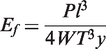
The chemical change occurred during aging and accompanied by a variation in molecular mobility. These variations were accounted by monitoring the Tg [5]. The variation of Tg of the composites is shown in Figure 4. After exposure to the three temperatures for one day, the Tg had an abrupt increase and the increase rate was higher at higher temperature. From the FTIR analysis, we knew that the initial cure reaction of the epoxy system left unreacted constituents. Consequently, the Tg increased due to the post-curing of the epoxy system. The amplitude of this process was to be maximized at 150℃, where the Tg reached a value of 136℃. After one day, the epoxide-anhydride reaction was almost complete in the case of 150℃ and the Tg tended to decrease as a result of molecular chain scission. However, the Tg did not continuously decrease but reached a relative stable value from the aging time of six days. It was because the oxidized surface layer effectively functioned as a passive layer, protecting the bulk epoxy from further oxidation. In contrast, the Tg at 90℃ and 120℃ continued to increase after one day. It was because the crosslinking reaction did not finish at the temperatures, further reaction was continuing with the increase of aging time.
Tg of the BC vs. aging time at different aging temperatures.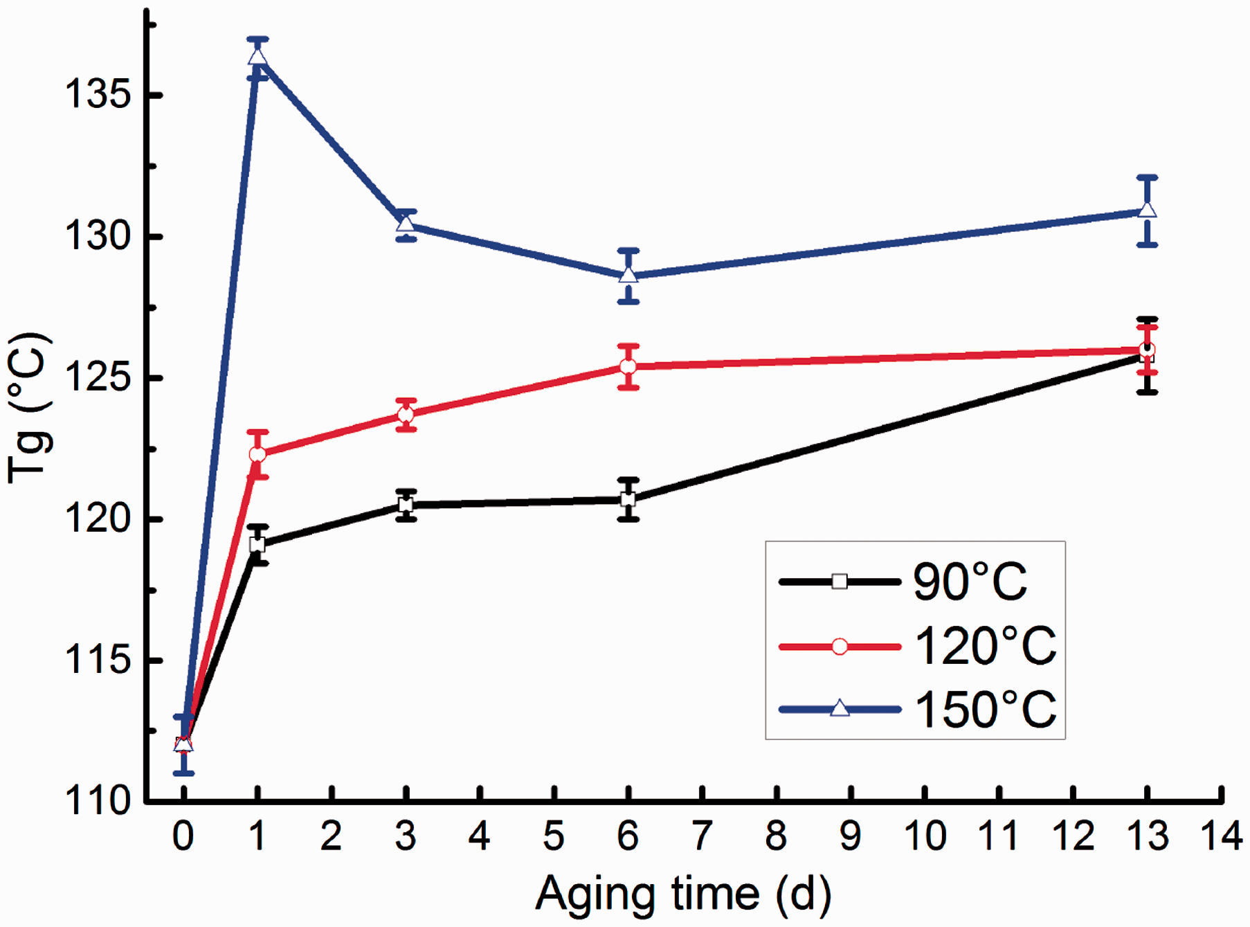
Weight loss analysis
Figure 5 illustrates the measured weight loss of the two composites at the three aging temperatures. It was found that the weight loss of the two materials increased with higher temperatures. Besides, the overall weight loss and the weight loss rate of the LC were about 1.25 times as high as those of BC under the same aging condition.
Weight loss of the two composites vs. aging time at different aging temperatures.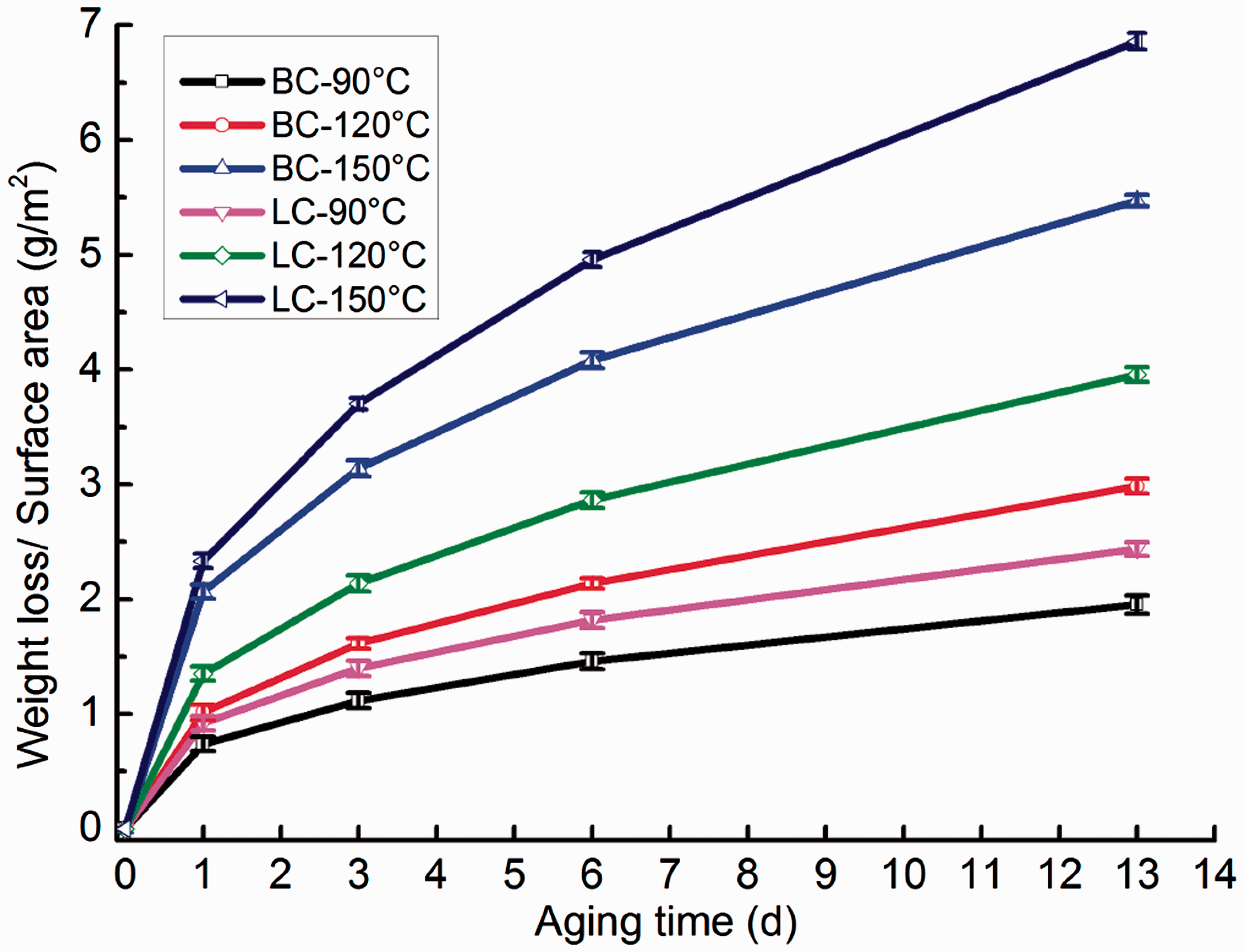
In the case of CFPMCs, weight loss was (in general) associated only with the polymer, as the reinforced carbon fibers were thermally stable at the temperatures considered in this work [37]. In this research, the two composites had the same matrix resin content (45%), so they should have the same weight loss. The weight loss of the two composites did not appear to follow the expected behavior that the weight loss of the BC specimens should be equal to that of the LC specimens, but rather the LC specimens lost considerably more weight than the BC specimens under the same aging conditions. It is because the surfaces of specimens with different microstructural characteristics are expected to exhibit different oxidation behavior [9]. A specimen with higher percentage of fiber end area exposed to air is more susceptible to interface oxidation, resulting in more weight loss [9,23,38]. The weight loss data presented in this article were an average of the values obtained from the flexural specimens, so the surface area ratio S2/(S1 + S2) for LC and BC was 24% and 3.9%, respectively. However, the plain weave fabric only had half of the fibers perpendicular to S2, so the actual fiber end area ratio of LC was 12%, which was three times more than that of BC. Therefore, the LC specimens lost much more weight than the BC specimens at the same aging condition, and the gap continued to be expanded with the increasing of aging time.
Flexural properties analysis
The flexural strength of a composite material is a measure of matrix strength and is very sensitive to the interfacial bonding between the fiber and matrix. The flexural strength should reveal any slight matrix weakening by oxidation. The design of the flexural test places the highest strain on the outer surfaces of the specimens. The outer surface is precisely the region that is expected to oxidize first [15]. Therefore, flexural strength is a sensitive indicator to reflect the property degradation of CFPMCs.
Typical results of flexural test are shown in the flexural stress-deflection diagrams in Figure 6. For both composites, the slopes of the curves and the ultimate flexural stresses decreased with the increasing of aging time at 150℃. In addition, both the unaged and aged curves of LC climbed in the form of saw-tooth before reaching the maximum stress. However, this phenomenon did not appear on both unaged and aged BC specimens, the curves of BC increased linearly till the peak values. After the peak values, there were sharp declines, then the curves dropped in stair-step shapes after short-term adjustment, but there were no saw-tooth waves.
Flexural stress-deflection diagrams of unaged and aged (13 days at 150℃) LC (a) and BC (b).
From the chemical and thermal analyses, we knew that the surface resin of the composites was oxidized when the specimens were exposed to 150℃ for 13 days, which should be responsible for the decrease of the flexural stress of the two composites. Besides, the interfacial bonding between fibers and matrix for the two composites was investigated before and after TOA. Figure 7 shows the typical SEM images of the fractured surfaces of the unaged and aged specimens. On fracture surfaces of both unaged LC and BC specimens (Figure 7(a) and 7(c)), fibers were covered with the matrix representing a good adhesion of fiber and matrix. The fractured surfaces were not significantly different between the aged BC and LC specimens. Resins attached to the fibers decreased and the grooves were formed due to the pull out of the fibers (Figure 7(b) and (d)). Besides, the fiber/matrix debonding and a large piece of resin were clearly visible on the fractured surfaces of BC (Figure 7(b)). The above phenomenon widely illustrated that the fiber/matrix interfacial bonding force became worse after TOA. Therefore, the chain scission of the matrix resin and the decrease of fiber/matrix interface bonding performance are jointly responsible for the decrease of the flexural stress.
SEM pictures of the fracture surfaces of unaged and aged (13 days at 150℃) BC (left) and LC (right).
The flexural properties’ retention rates of the two composites were used to compare the effect of reinforced structures on the TOS of CFPMCs. The difference between BC and LC in flexural strength and flexural modulus retention rates vs. aging time at different aging temperatures is shown in Figures 8 and 9, respectively. From Figure 8(a)–(c), it can be seen that the flexural strength decreased with higher aging temperatures and longer aging times, which was consistent with the FTIR and SEM analysis results. From the FTIR and SEM analyses, we knew that the surface resins and the fiber/matrix interface of the composites were oxidized more and more seriously with the increase of aging time and aging temperature, so the flexural strength decreased with higher aging temperatures and longer aging times.
Difference between BC and LC in flexural strength retention rate vs. aging time at different aging temperatures. Difference between BC and LC in flexural modulus retention rate vs. aging time at different aging temperatures.

From Figure 9(a), it can be seen that the flexural modulus of the two composites increased by 0.25–2.5% after exposure to 90℃. It may seem contradictory that while the strength values decreased consistently with TOA, the stiffness increased in the same time frame. However, the above two observations seemed quite logical and in fact were connected to each other. The increase of the modulus may be attributed to the densification and brittleness of the matrix resin as a result of physical aging [39] and post-curing. The enhanced brittleness may introduce defects in the specimens, such as microcracks, which could have an adverse effect on the flexural strength. In contrast to 90℃, the flexural modulus decreased with the increase of aging time after exposure to 120℃ and 150℃ (Figure 9(b) and (c)) due to the oxidative degradation of the matrix resin and the fiber/matrix interface.
In addition, the flexural strength and modulus retention rates of BC were higher than those of LC at the same aging condition (Figures 8(a)-(c) and 9(a)–(c)). In order to quantitatively compare the difference between BC and LC in flexural properties, the flexural strength and modulus retention rates of LC were subtracted from those of BC at the same aging condition, the corresponding results are shown in Figure 8(d) and Figure 9(d), respectively. The difference between BC and LC in flexural strength retention rates (Figure 8(d)) and flexural modulus retention rates (Figure 9(d)) at the same aging condition increased with the increase of aging time and aging temperature. It illustrated that the superiority of BC in TOS will be more and more obvious than that of LC when the resin was damaged seriously and the adhesive force between fiber bundles and resin decreased significantly after TOA.
The two composites had the same constituent materials, so the difference in TOS could only be attributed to the difference of the reinforced structures. In order to find out the reason of the difference in TOS of the two composites, the failure modes of the two composites were investigated. Figure 10 shows the photomicrographs of the side surfaces of the two composites after exposure to 150℃ for 13 days compared to the unaged ones.
Photomicrographs of side face of unaged and aged (13 days at 150℃) BC (left) and LC (right) after flexural test.
Once a specimen surface was suffered by the loading nose, it would produce compression stress perpendicular to the specimen surface, and then the stress would propagate along the specimen thickness direction to the back of the specimen and finally be reflected to form the tensile stress. With the increase of the deformation of the specimen, the tensile stress would be turned into interlaminar stress. For LC, there were only resins (red area) between layers (Figure 11), so cracks were once formed between the layers, they were prone to spread along the interlamination, and finally leading to delamination damage (Figure 10(c)). This phenomenon would be exacerbated (Figure 10(d)) when the resin was damaged and the adhesive force between fiber bundles and resin decreased after TOA. Therefore, the saw-tooth in the stress-deflection curves (Figure 6(a)) was the characteristic of delamination damage, and each dip in the saw-tooth was on behalf of every delamination. As the delamination damage became seriously on the aged specimen than the unaged one, the bigger saw-tooth appeared on the stress-deflection curve of the aged specimen. With the increase of the deformation, the transverse shear force between layers would promote interface cracks to extend, and then the flexural load was quickly passed to fibers when the cracks extended to the interface of fiber and matrix. Under the tension stress, the fibers fractured, finally lead to the complete break of the specimen. Therefore, the longitudinal cracks were generated across the whole thickness of both unaged and aged specimens (Figure 10(c) and (d)). The LC failed in the form of delamination, the single layer was not enough to resist flexural load, so all warp and weft yarns of the LC specimens under the loading nose fractured, and the cracks penetrated the whole width direction of the specimens (Figure 13(c) and (d)). For BC specimens, all braiding yarns embraced together forming a fully integral structure (Figure 1(a)) which may enable it to mechanically interlock. Even if the cracks are formed at the interlaced place of braiding yarns, such as the red areas in Figure 12 [40], they will be hindered by the neighboring braiding yarns. Therefore, only a few cracks appeared at the interlaced place of the braiding yarns, but no delamination happened on unaged and aged BC specimens (Figure 10(a) and (b)). The stresses had a big drop after the peak values (Figure 6(b)), which may be due to the damage at the interlaced place of the braiding yarns. At this time the braiding yarns may have a certain dislocation, after the short adjustments, all the braiding yarns tightly embraced together again to bear the flexural load. With the increase of the deformation, the position of the braiding yarns was constantly adjusted, so the curve decreased in stair-step shapes. As the BC specimens resist the flexural load as an integral structure, the cracks on the compressive faces were not centered under the loading nose but randomly distributed in a big area (Figure 13(a) and (b)).
Idealized representation of laminated plain woven fabric composite. SEM micrograph of the interior structure of a 3D-4Dir braided perform. Photomicrographs of compressive faces of unaged and aged (13 days at 150℃) BC (left) and LC (right) specimens after flexural test. The red areas were the locations of cracks.

Compared with the traditional laminated composite reinforced by the plain woven fabric, the TOS reinforcing mechanism of the integral composite structure reinforced by the 3D-4Dir braided preform can be summarized as two aspects: (1) the BC specimens, having lower fibers open ends, had shown lower weight loss, compared to the LC specimens. As the weight loss can cause microcracks and voids, leading to degradation of the mechanical properties [41], the lower weight loss would lead to less degradation in the flexural properties; (2) for the LC, there are only resins between the two layers, so the delamination damage is prone to happen when the resin was damaged and the adhesive force between fiber bundles and resin decreased after TOA. In contrast, for BC, all braiding yarns embraced together forming an integral structure which may enable it to mechanically interlock, even if the cracks are formed at the interlaced place of braiding yarns, they will be hindered by the neighboring braiding yarns. Therefore, the BC can resist the flexural load as an integral structure although the resin was damaged and the adhesive force between fiber bundles and resin decreased after TOA, and no delamination happened like the LC.
Conclusions
TOA of BC and LC were conducted in air-circulating ovens set at 90℃, 120℃, and 150℃ for various periods of time up to 13 days. The process resulted in progressive deterioration of the matrix reins and fiber/matrix interfaces, in the form of chain scissions, weight loss and fiber/matrix debonding, which significantly led to the decrease of the flexural strength. However, at the same TOA conditions, the flexural properties’ retention rates of BC were always higher than those of LC due to the difference of the reinforced structures. Compared with the traditional laminated composite reinforced by the plain woven fabric, the TOS reinforcing mechanism of the integral composite structure reinforced by the 3D-4Dir braided preform can be summarized as two aspects: On the one hand, the BC specimens, having lower fibers open ends, had shown lower weight loss, compared to the LC specimens. The lower weight loss caused less microcracks and voids in the BC, leading to less degradation in flexural properties; On the other hand, for BC specimens, all braiding yarns embraced together forming an integral structure which may enable it to mechanically interlock, even if the cracks are formed at the interlaced place of braiding yarns, they will be hindered by the neighboring braiding yarns. Therefore, the 3D-4Dir braided composites can resist the flexural load as an integral structure although the resin was damaged and the adhesive force between fiber bundles and resin decreased after TOA. However, for the LC, there are only resins between layers, so the delamination damage is prone to happen when the resin was damaged and the adhesive force between fiber bundles and resin decreased after TOA. Therefore, the integral structure of the 3D-4Dir braided composite may be a good compensation for the loss of flexural properties caused by the degradation of resin and fiber/matrix interface after TOA. These results demonstrated that the 3D-4Dir braided structure have an obvious reinforcing effect on the TOS of CFPMCs, which provides an easy and effective way to design and improve the durability, safety, and reliability of CFPMCs that are increasingly the material of choice in the aerospace industries. For instance, the 3D-4Dir braided structure may be used as components for the aero-engine exposure to high temperature environment.
Footnotes
Declaration of Conflicting Interests
The author(s) declared no potential conflicts of interest with respect to the research, authorship, and/or publication of this article.
Funding
The author(s) disclosed receipt of the following financial support for the research, authorship, and/or publication of this article: The authors wish to acknowledge the sponsorship of Tianjin Municipal Science and Technology Commission, China (Nos.10SYSYJC27800, 11ZCKFSF00500 and 13TXSYJC40500).