
Abstract
Technical fabrics find extensive use as reinforcement in plastic components across various applications. Traditionally, these fabrics are produced using wide weaving machines with a constant fabric width and are then cut to achieve the desired component geometry, leading to significant waste generation. An effective approach to minimizing waste and conserving resources involves utilizing fabrics with outer contours that match the desired component geometry from the outset. Until now, the production of width-variable fabrics during the weaving process has not been achievable using wide weaving machines. Addressing this limitation, this paper introduces a novel reed design specifically developed for wide weaving machines. The paper presents the design concept of the new reed and elucidates the fabric development process associated with its implementation. Furthermore, the resulting fabric properties and physical relationships are demonstrated based on manufactured samples. By enabling the production of width-variable fabrics, this innovative approach aims to contribute to more sustainable manufacturing practices in the field of technical fabrics—reducing waste and optimizing resource utilization.
Keywords
Introduction
Fibre-plastic composites offer significant potential for lightweight construction due to their unique structural design. These composites combine high-performance fibres like carbon, glass or aramid for load transfer along the fibre’s length, along with a plastic matrix responsible for handling compressive and shear loads.1–3 As a result, these composites exhibit exceptional anisotropic material properties with high specific tensile strength and stiffness in the direction of reinforcement. 4 The manufacturing process of these composites involves several stages, including textile semi-finished product fabrication, preforming, infiltration and consolidation. 5
Conventional preforming typically involves cutting textile reinforcement structures with homogeneous surface structures into sizeable portions. These portions are then laid down, stacked, formed, and partially pre-fixed to create the desired component. 6 However, this method relies solely on geometric design and alignment of cut parts to address specific load cases. Consequently, it leads to cutting losses and necessitates over-dimensioning due to unfavourable reinforcement thread courses. To address these constraints, advancements in textile manufacturing processes have been extensively pursued. These developments aim to enable the direct integration of required component geometries into the manufacturing process through the textile structure.7–9 However, when dealing with large-format shell-shaped components, a challenge arises in accommodating component-specific textile structures. Presently, there are no existing solutions for adjusting the component width to align with the fabric width, especially in the production of textiles. Woven fabrics are commonly used to reinforce fibre-reinforced plastic composite components. The traditional production process results in a constant yarn orientation and fabric width. Several developments have attempted to alter this in the weaving process. For instance, open reed weaving enables a limited lateral offset of additional threads (≤300 mm) along the existing lines of force allowing for improved reinforcement.10,11 However, it cannot achieve local changes in warp yarn density or adjust fabric width to produce near-net-shape fabric structures.
To change the fabric width and thus the warp yarn density on weaving machines, the fineness of the reed must be adjustable during the weaving process. V-shape reeds can be used to change the fabric width. 12 However, these are limited to narrow weaving machines and cannot be used in wide weaving machines. Only the shuttle weaving of the company Mageba International GmbH allows the use of V-weaving reeds. However, the maximum nominal fabric width is 1000 mm.
Numerous innovations and improvements have been made for wide weaving machines, especially rapier weaving machines. 13 However, none of these developments concerns changing the fabric width in the weaving process. Only special designs that have remained in the development stage have been carried out. For example, grooved roller mechanisms, 14 concertina mechanisms, 15 or segmented rail mechanisms 16 were carried out. None of the methods could establish themselves industrially because of either low flexibility, complex elaborate construction or a high moving mass. Given the limitations of existing methods, a new reed concept was developed in this paper to address the shortcomings and offer a viable solution for adjusting warp density and fabric width during fabric production on rapier weaving machines, particularly for wide weaving machines with a working width over 1000 mm. This innovative reed design not only ensures the required flexibility and accuracy but also paves the way for producing reinforcement fabrics that precisely match the final contour of the component. Besides the constructive details, an investigation of the fabric properties has been made. This provides information about the challenges and complexity of controlling the fabric width changes during weaving, especially the changing warp yarn angles which has been influenced by the adjustment of the reed.
Constructive developments
Constructive development and implementation of a variable-width reed for adjustment of warp density in rapier weaving
A new type of variable-width reed was developed to change the warp density and consequently the fabric width during the fabric production. This reed is designed to allow the distances between the reed bars to be adjusted by an external force, achieved by compressing segments located between the reed bars. This adjustment enables changes in fabric width during the weaving process (see Figure 1). For the developed constructive solution the force is applied to the segments through a linear spindle unit powered by laterally mounted stepper motors on the weaving machine that drive the spindles using a flexible shaft. The reed bars and segments are threaded onto a guide shaft to prevent any breakage. The design of the reed allows for asymmetrical adjustments in warp yarn density and fabric width. This is made possible by the independent control of two laterally mounted stepper motors, while the middle reed bar remains firmly clamped during the process. The stepper motors are installed on the left and right side of the reed outside the fabric production zone. This asymmetrical adjustment capability offers a significant advantage as it allows for the accurate replication of component geometries during the weaving process. The entire design is shown in Figure 2. The reed is configured to facilitate the transmission of rotary motion from the stepper motors to the spindles through flexible shafts. These shafts in turn regulate the carriage positions, compressing the springs between the reed rods and thereby altering the fabric width. Principe of developed variable-width reed. Constructive solution of variable-width reed; technical presentation.

The variable-width reed has an initial fineness of 18 reed gaps per 10 cm in its “wide state,” which can be compressed to up to 36 gaps per 10 cm, providing a wide range of adjustments. The reed has an initial working width of 115 cm, making it compatible with standard rapier weaving machines. Referring to these technical properties the width of the fabric can be reduced up to 50%. To demonstrate the practical application of the variable-width reed, it was installed in a rapier weaving machine P1 from Lindauer Dornier; Germany (see Figure 3(a)). To minimize warp cross-drawing forces and maintain the set reed fineness during adjustments, a shearing reed was installed between the creel and the back-rest (see Figure 3(b)). This additional reed ensures that the warp yarns are guided smoothly through the variable-width reed without distorting the set reed fineness. (a) installation of developed flexible reed, (b) installation of comp.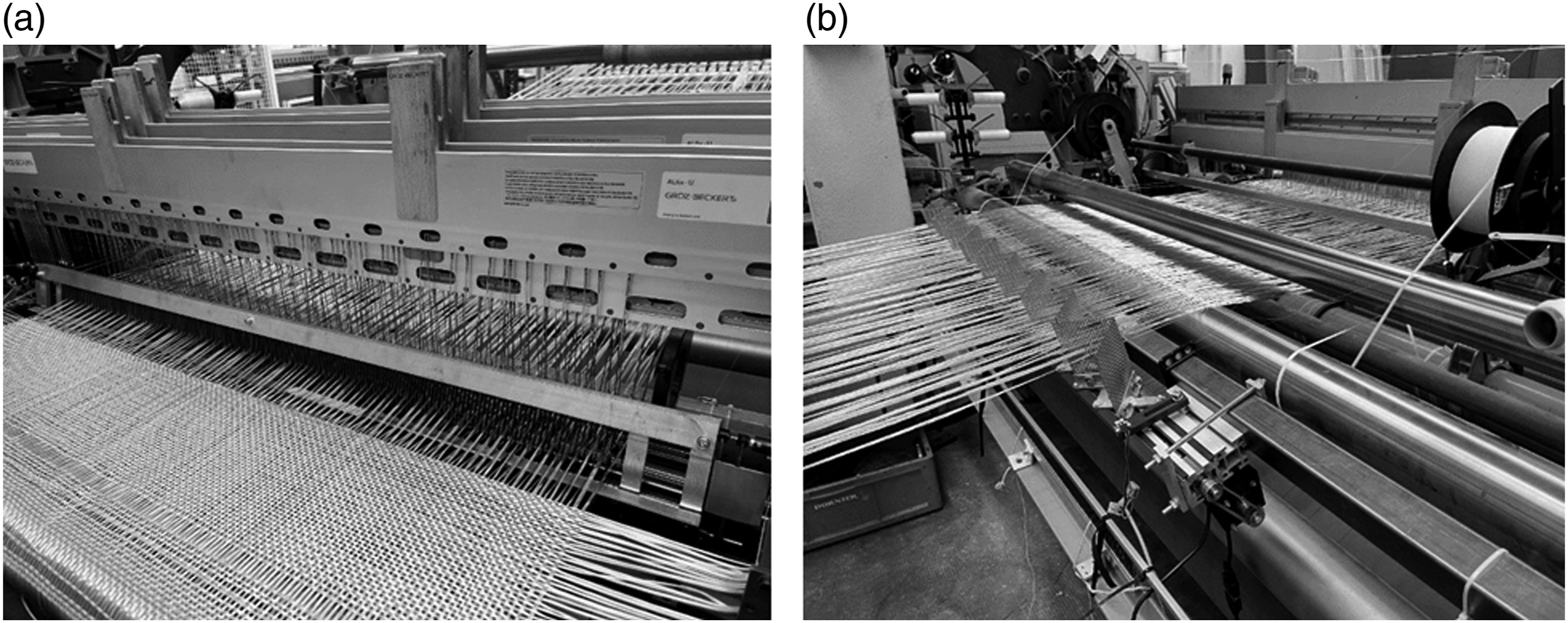
Development of calculation tool to design the weave fabrics and control the stepper motors motion to change the fabrics width:
During the weaving process, dynamically modifying the warp yarn density poses challenges in maintaining a consistent fabric density. When the fabric density is too high excess material accumulates at the fabric edge impeding further weft insertion due to a small weaving shed. Conversely, if the fabric density is too low, the binding of weft yarns becomes loose making structural handling more challenging. To ensure feasible weaving of textile structures within the producible range, it becomes necessary to adapt the weave pattern and/or weft yarn density to the fabric width. This adjustment ensures a balanced fabric density enabling smooth and efficient weaving processes while maintaining the structural integrity of the composite.
The equation developed by Walz and Luibrand is used to calculate the relative fabric density.
17
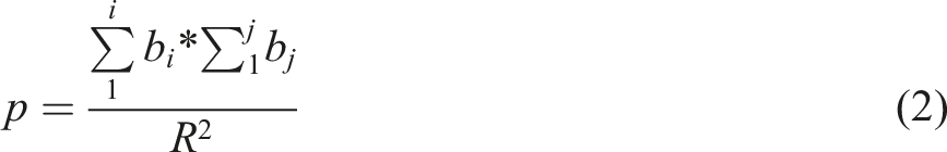
Equation (1) can be utilized to calculate the required weave patterns for varying fabric widths. The computation of fabric density relies on the multiplication of diameters by the sum of squared warp and weft yarns considering the respective yarn densities. The result is further multiplied by a weave-specific factor, derived from summing the crossings of warp and weft yarns within the weave repeat in both warp and weft directions and subsequently dividing by the maximum potential crossings. To produce a fabric with varying fabric width, the resulting fabric density must remain constant. For this purpose, the theoretical density factor (Equation (2)) is calculated and the corresponding weave pattern is assigned to maintain a constant relative fabric density. Alternatively, the weave pattern itself is kept constant along the fabric to be produced and only the weft density is adjusted. DG Fabric density p Theoretical density factor d Filament diameter nk Warp density ns Weft density p Theoretical density factor bi Cross-sections along warp direction bj Cross-sections along weft direction R Maximal cross-sections within the rapport size

To generate the necessary weave pattern file and facilitate the adjustment paths for the stepper motors based on required fabric widths, a program routine was developed. This routine allows fabric production by reading in the STL (Standard Transformation Language) file from CAD software, calculating widths along a user-selected grid.
The challenge arises from the fact that the point cloud data in an STL file does not provide all points required to determine accurate fabric widths for each individual weft yarn. To address this, the program first captures the points of the left and right outer contour of the STL file. Subsequently, a vector is created using the ‘linspace' function between the lowest and highest edges of the fabric, tailored to have points with distances corresponding to the selected grid facilitating interpolation. Using the ‘interp1’ function, an interpolated function is established to map the outer contour of the fabric. The coordinates of the determined outer points serve as supporting points in this process. The program accurately calculates outer points corresponding to the distances of the grid points representing the number of weft yarns to be inserted in the weaving process. The fabric width for each individual weft is then calculated using these outer points (see Figure 4). Programme routine to calculate the stepper motion up to the required fabric width.
To generate the weave pattern, warp yarn densities are calculated based on the calculated fabric widths. For this purpose, the desired number of warp yarns is entered. Equation (1) is used to calculate the weft densities for the areas ensuring that the relative fabric density remains constant. The calculation includes the fineness of the warp and weft yarn material to be used and the fabric density to be woven. To ensure a constant fabric density along the produced fabric, the weave can alternatively be adjusted according to the changing fabric width. The theoretical density factor of the weave pattern p (see equation (2)) is calculated based on the existing warp yarn density, the desired constant fabric density and a fixed weft density. Corresponding weave patterns are then assigned. Both variants can be combined, allowing for variation in both the weave pattern and the weft density based on the fabric width.
To calculate the motion of the stepper motors, the outer points of the calculated geometry are used. For this purpose, the individual differences of the lateral values of the successive outer points are calculated for the right and left halves of the fabric. These differences form the required adjustment paths of the stepper motors implemented as an array in the Arduino control of the stepper motors.
Experimental investigations
Development of width-variable fabrics
To validate the developed technology, fabric samples with variable fabric widths were produced using the new weaving process. Two fabric samples were designed for this purpose. Both consist of plain weave with different fabric widths. The first fabric sample exhibits a symmetrical change in fabric width, starting at 1000 mm and gradually reducing to 650 mm over a total fabric length of 1920 mm (see Figure 5(a)). The second fabric sample presents an asymmetrical outer contour with the left side of the fabric width reducing from 500 mm to 325 mm, while the right side alternates between reducing by 100 mm and extending again (see Figure 5(b)). Geometry of fabric weaves example: symmetrical fabric (a), asymmetrical fabric (b).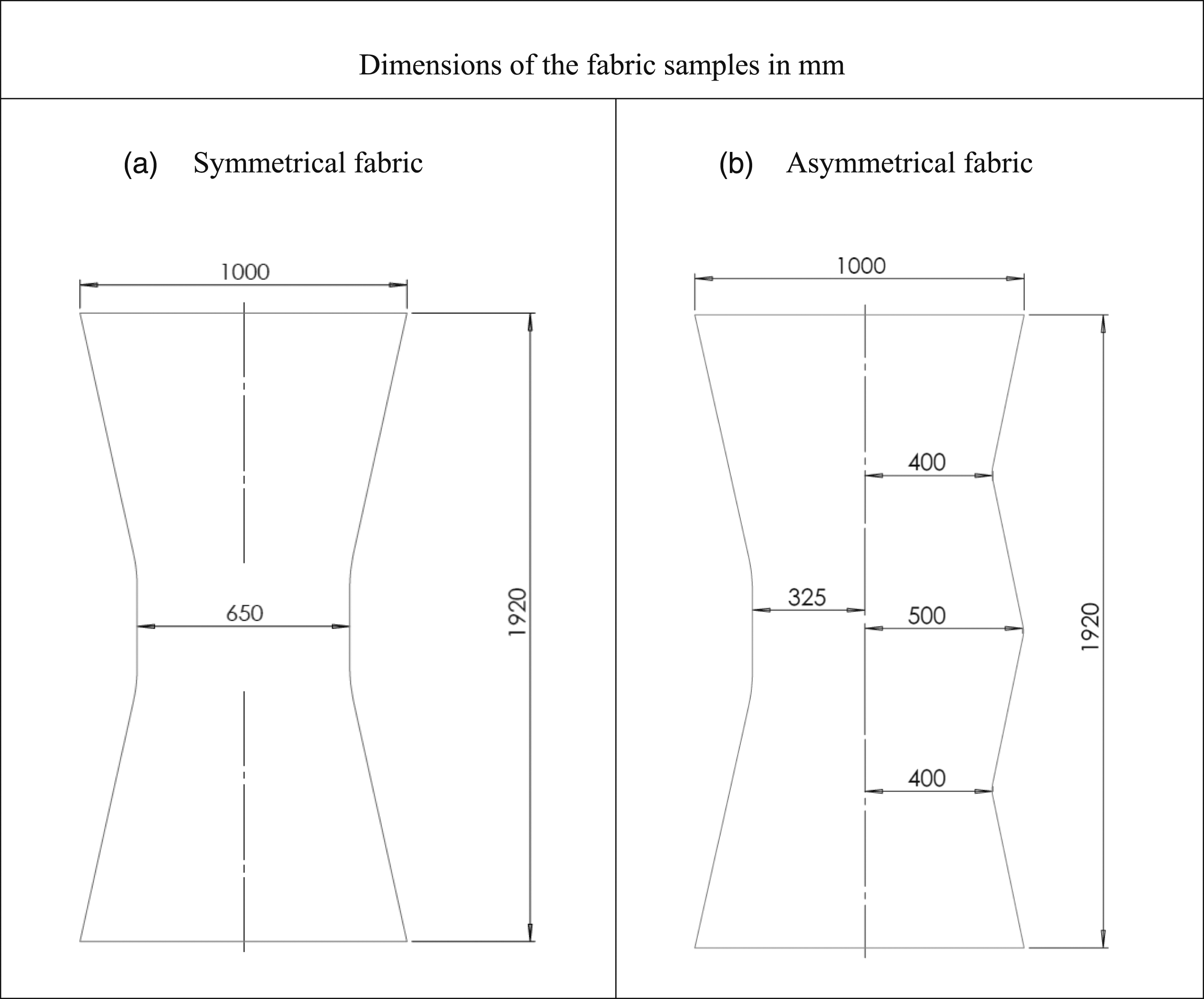
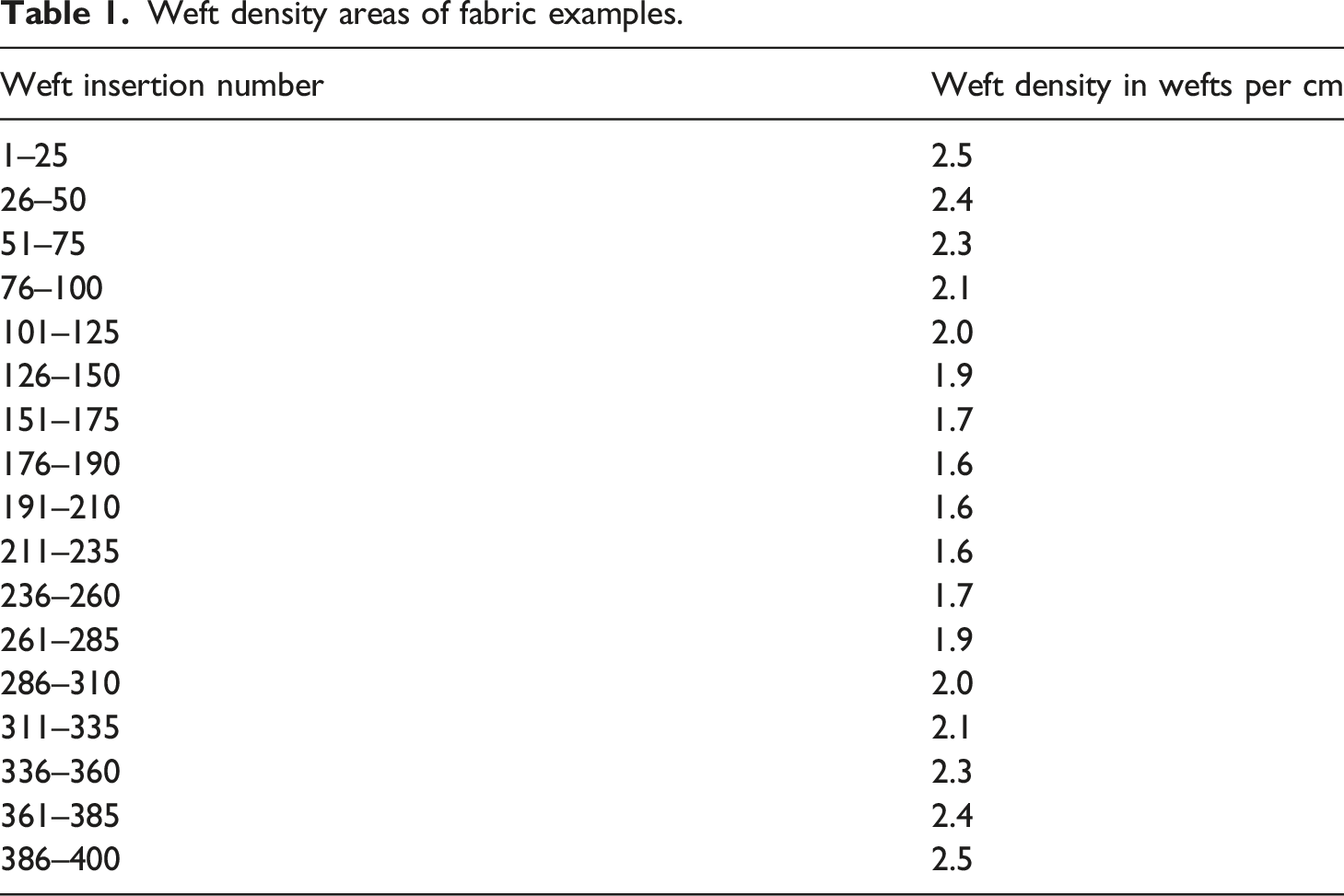
Weft density areas of fabric examples.
The motion of the stepper motors was monitored using the developed programme routine, aligning with the required fabric width. Subsequently, the weave pattern file and the associated programming for the weft density ranges were created to be used on the rapier weaving machine. The control file for moving the stepper motors was then integrated into the developed control unit. Finally, the fabric samples were manufactured as shown in Figure 5.
Results
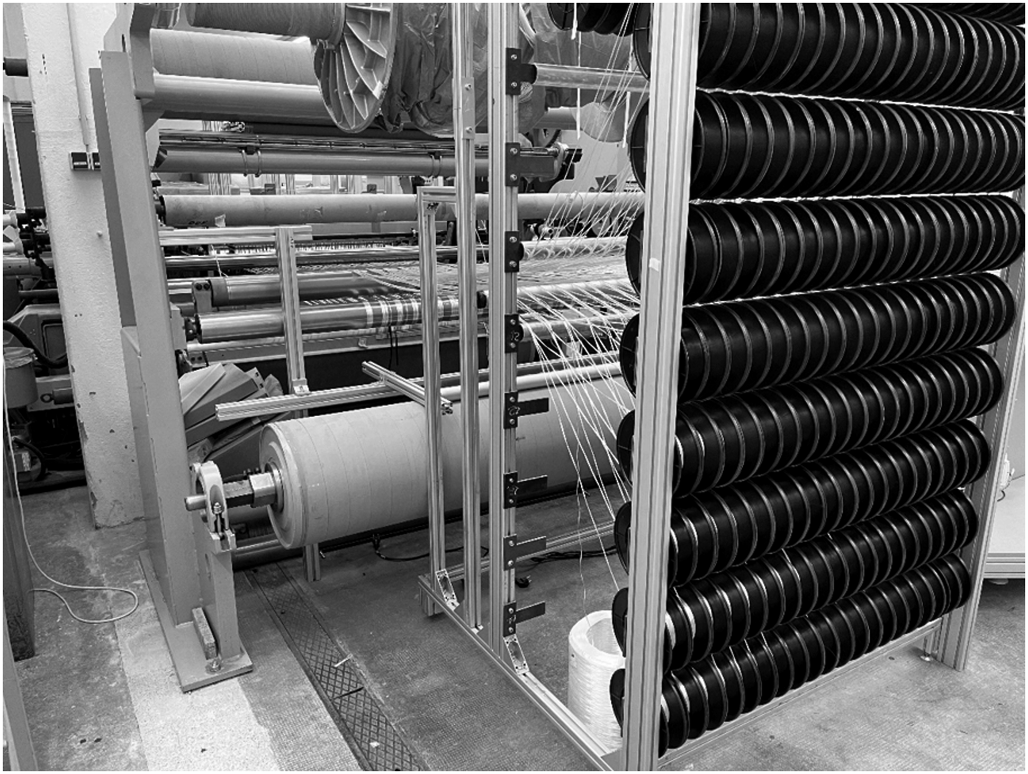
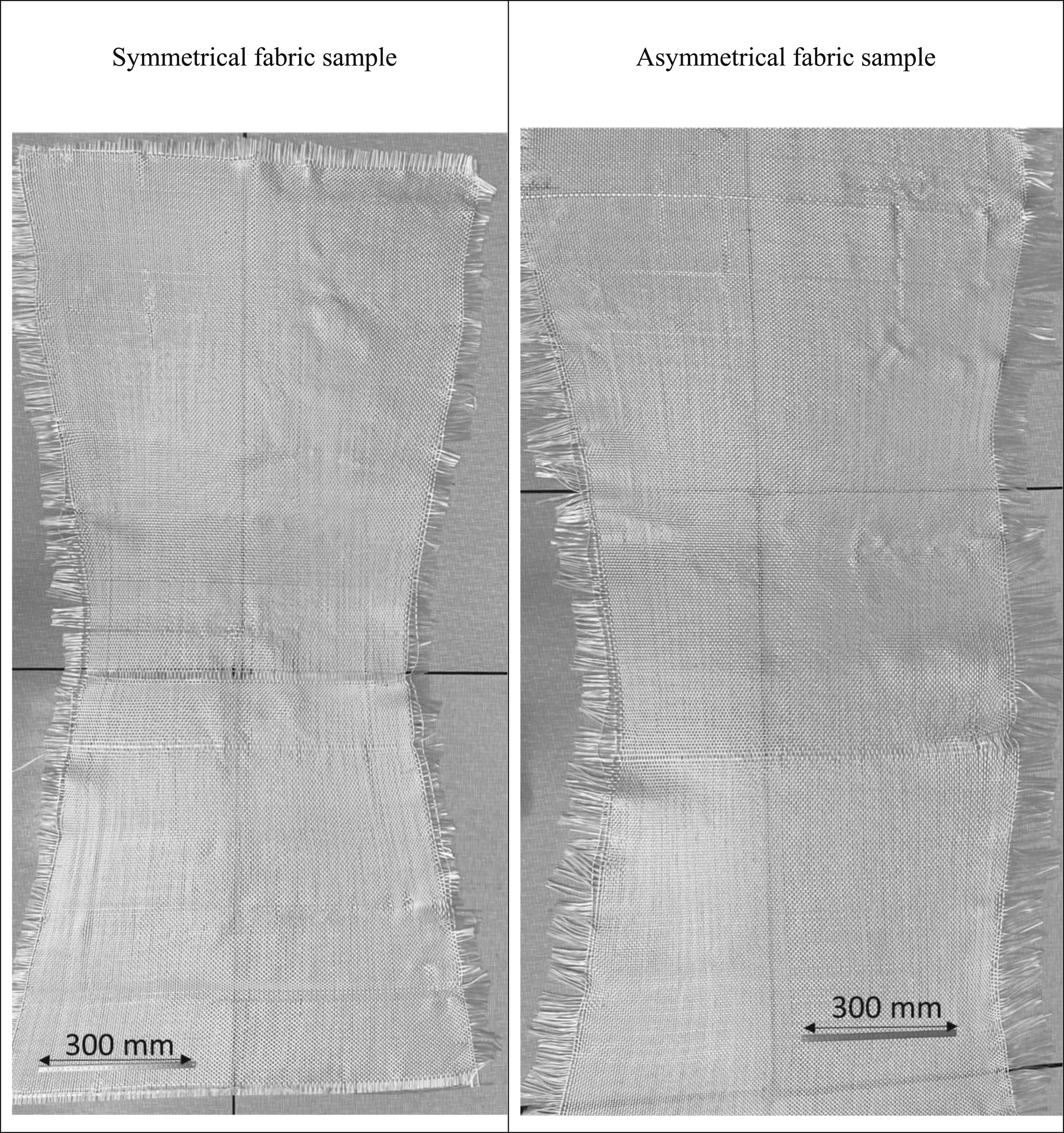
The developed width variable fabrics were produced using a broad loom from Lindauer Dornier (Germany); rapier weaving machine P1 (see Figure 6). The warp yarns were supplied from a creel with passively braked spools (see Figure 7). The creel was constructed within the institute. After setting up the loom the fabric samples, encompassing both the plain weave and varying weft densities, has been manufactured. The result is the creation of fabric samples made up of glass fibre (1200 tex) (see Figure 8). The results demonstrating the successful implementation of the variable fabric widths and confirming the viability of the developed technology. Fabrication of fabric examples. Installed creel for feeding the warp yarns. (a) symmetrical fabric sample, (b) asymmetrical fabric sample.
Evaluation of the fabric outer contour
To determine the outer contour of the fabricated fabric samples, measurements of fabric widths were taken. The measurement of the fabric width was done by using DIN EN ISO 1773. The fabric width was measured at intervals of 10 weft yarns each. In the case of the asymmetrical fabric sample, measurements were separately taken for the right and left fabric halves corresponding to the fixation of the middle reed bar of the weaving reed.
The mean deviation of the first fabric sample was found to be 0.8%. However, a hysteresis effect was observed from the reversal point up to the halfway point of the fabric. The stepper motors' rotation led to an adjustment of the slides, with a shift of 2 mm per weft insertion, both for fabric reduction and expansion. The rate of change from weft one to weft 190 (up to the reversal point at 650 mm) was measured at 1.99, closely resembling the movement of the slides of the weaving reed. Beyond weft 210, the weaving reed returned to its initial width, resulting in a rate of change of 1.95 mm per weft, leading to a deviation of 2.5%. At weft 190, the fabric contour exhibited a fabric width of 658 mm, which reduced to 653 mm by weft 210. As a result, the reduction of the fabric width lagged behind within the narrowest point (see Figure 9). The hysteresis effect arises from the variation in the warp yarn angle between the reed and the fabric take-off, which occurs as a consequence of adjustments in the reed fineness and, consequently, changes in fabric width. This alteration induces a lateral force on the reed bars and the interposed springs. Outer contour of symmetrical fabric sample.
To measure the outer contour of the asymmetrical fabric sample the width was measured up to the middle of the fabric. The behaviour of the left half of the fabric corresponds simultaneously to the symmetrical fabric sample. Considering that a single motor’s change causes a 1 mm adjustment per weft, the resulting rate of change in the fabric width from weft 1 to 190 was 0.99 mm per weft and from weft 210 to 400 was 0.96 mm per weft.
On the right side of the asymmetrical fabric sample, the fabric width was reduced by 100 mm over a interval of 100 weft insertions and then increased again accordingly. The rate of width change from weft 1 to 100 was measured at 0.93 mm per weft insertion resulting in a width change of 93 mm at the 100-weft reversal point. From weft 100 to 200, the fabric width increased at a rate of change of 0.77 mm per weft, leading to a fabric width of 485 mm and a deviation from the initial width of 3%.
Starting from this point, the fabric was reduced again at a rate of change of 0.77 mm per weft. The deviation from the first range (weft 1 to 100) is attributed to the fact that while the stepper motors execute the movement completely, the distances between the reed bars do not follow to the same extent. Consequently, the adjustment rate within the fabric is lower for the renewed reduction, as the starting point for this adjustment is the reversal point at weft 200. However, the increase in fabric width between weft 300 and 400 is again 0.78 mm per weft, consistent with the previously achieved ranges. In summary, it can be concluded that after a single adjustment, both the reduction and increase in fabric width result in a rate of change of 0.77 mm to −0.78 mm per weft (see Figure 10). This discrepancy arises because, following the reduction in fabric width, the lateral forces exerted by the tensile forces of the warp yarns oppose the compressive forces of the spring elements. Consequently, this opposition hinders the widening process when the fabric is later expanded. Outer contour of asymmetrical fabric sample.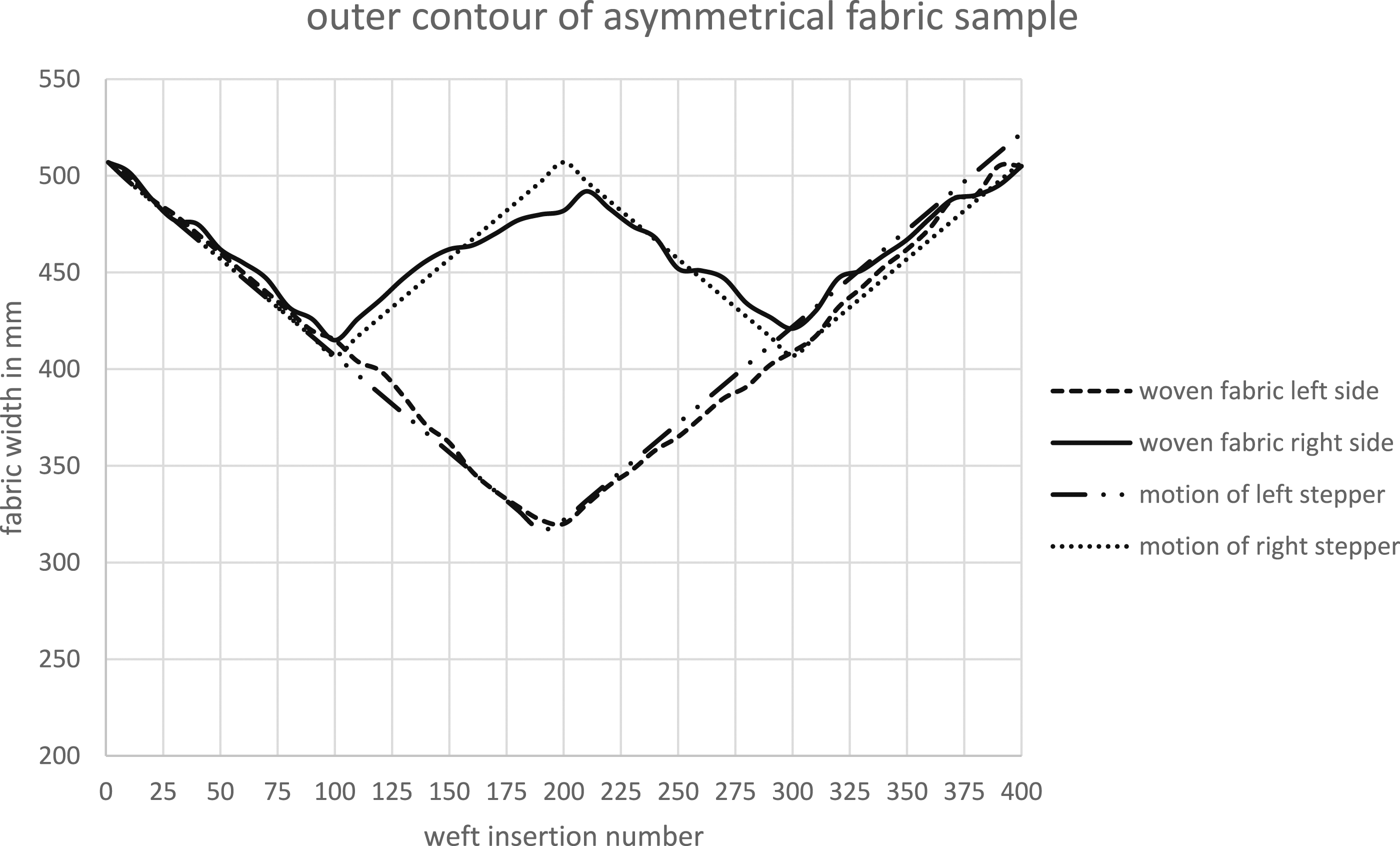
Evaluation of warp yarn density
The evaluation of warp density was conducted on eight different fabric widths along the fabric samples. Within each fabric width, measurements were taken at the left and right fabric outer edges, as well as in the middle resulting in a total of 24 measurement samples for each fabric sample. A standardized 10 × 10 cm square was used as the measurement sample geometry for consistency. The measurement of the warp density was done by using DIN EN ISO 1049-2. The symmetrical fabric sample displayed a significant variation in warp density between the edge areas and the middle. Specifically, at the narrowest fabric width of 650 mm, there was a 30% difference in density (see Figure 11). This indicates that the compression of distances between the reed bars is not uniform across the fabric width. Warp density of symmetrical fabric sample.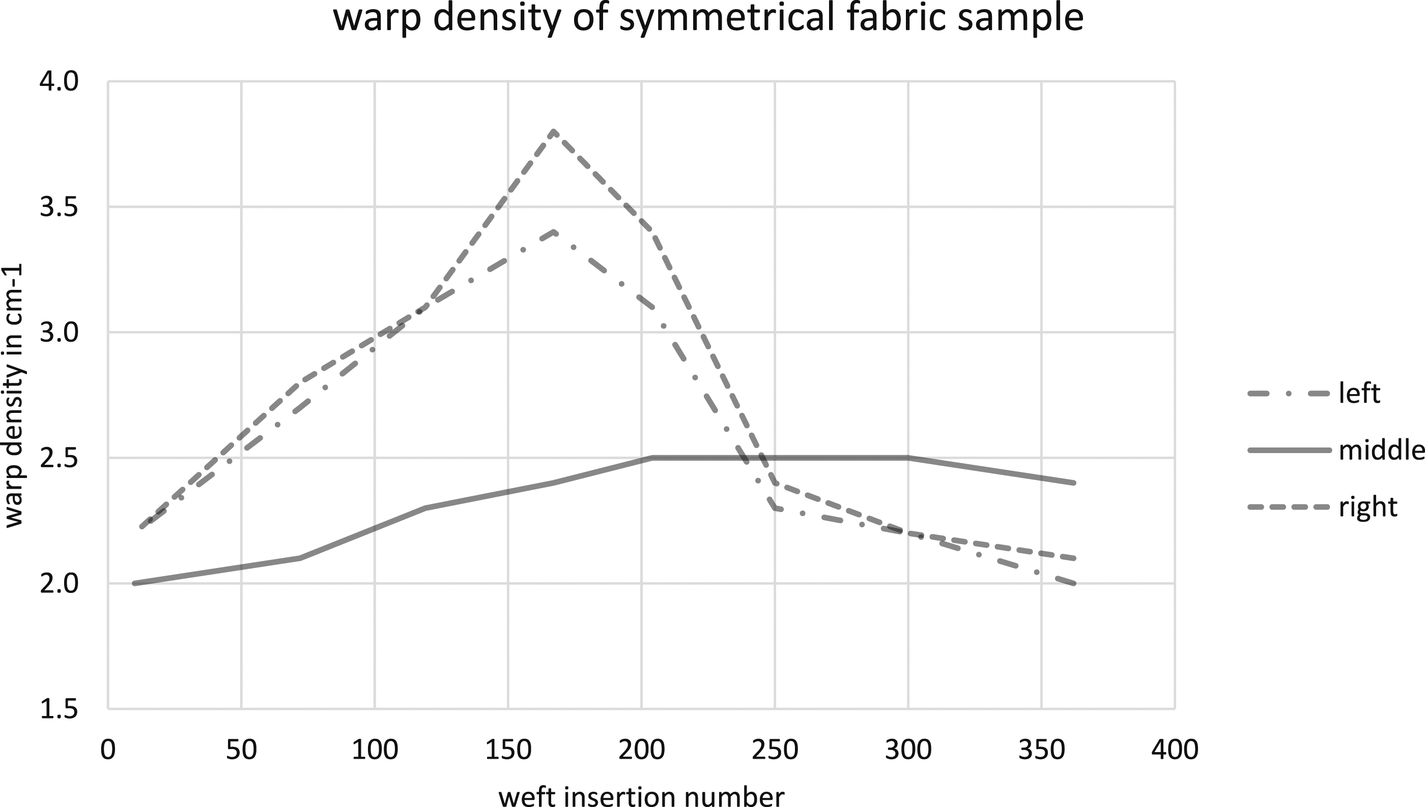
In the case of the asymmetrical fabric sample the warp density revealed an asymmetrical fabric width course. Similar to the symmetrical fabric sample, the warp density on the left half of the fabric increased up to the maximum fabric width reduction and then decreased accordingly (see Figure 12). On the other hand, the right half of the fabric exhibited alternating changes in fabric width with the warp density increasing by 20% and then decreasing again. Warp density of asymmetrical fabric sample.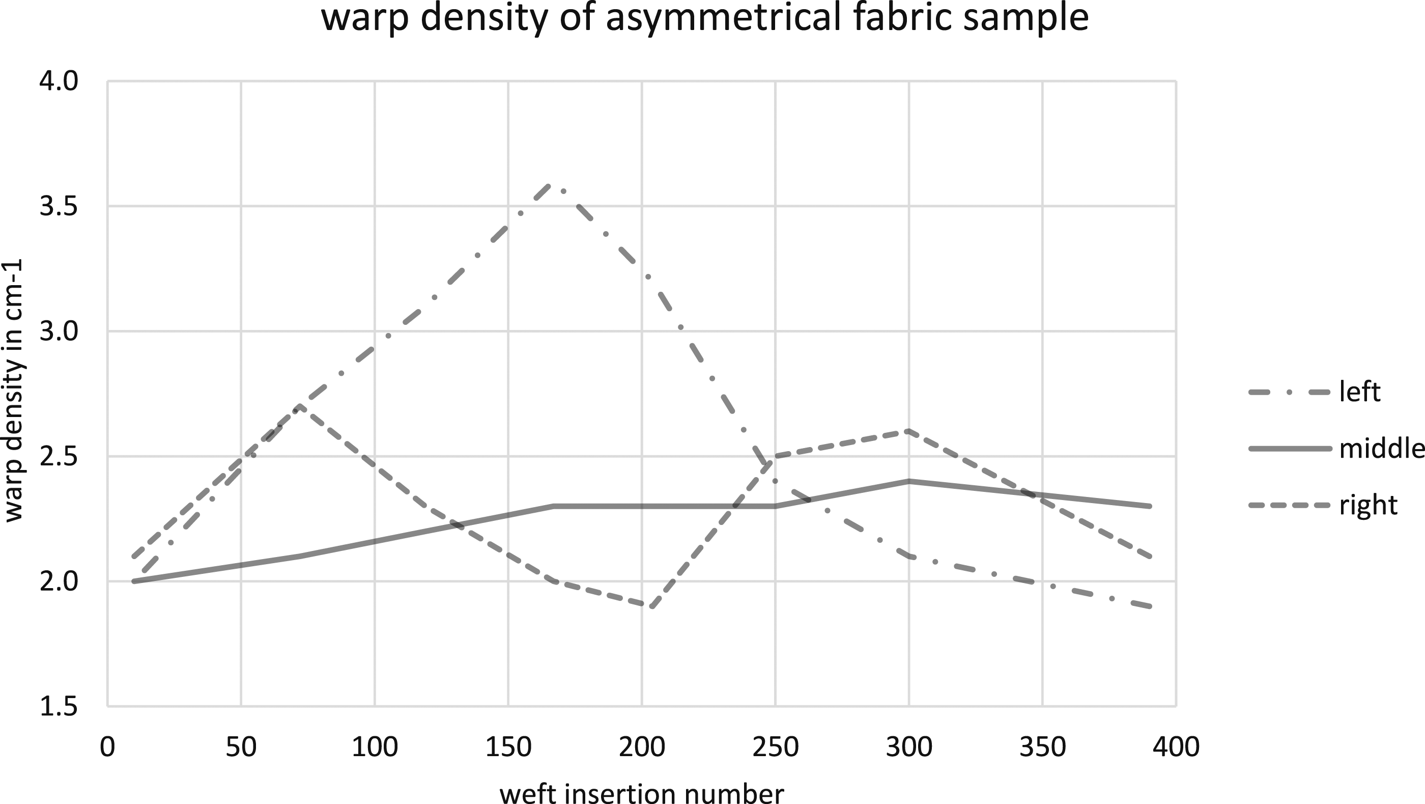
To ensure that the warp density along the fabric width is more homogeneous in the fabric, further design developments are to be provided for the variable-width reed. For example, a better, more uniform distribution of the reed gaps in the reed can be achieved by selecting the spring elements between the reed bars.
Evaluation of the square mass
To determine the mass per unit area, 10 × 10 cm measurement sample areas were separated from the fabric samples used for evaluating the warp density and weighed. This allowed for the measurement of the basis weight along the fabric samples at the outer edges and in the middle. The measurement was done by using ASTM D 3776. For the symmetrical fabric sample the mass per unit area of the sample pieces revealed that despite the reduction in weft yarn density, the basis weight at the fabric edges increased with the reduction of fabric width. Specifically, the basis weight increased by 6.5% from weft one to the reversal point at weft 200, for both the left and right fabric sides (see Figure 13). In contrast, the middle of the fabric sample showed a reduction in basis weight up to weft 200. This occurred because, while the warp density exhibited minimal variation in the outer regions, the weft density experienced consistent changes across the entire fabric width. As a result, the fabric in the middle had an overall lower fabric density and consequently a lower basis weight. However, from the point of renewed widening of the fabric width, the mass per unit area in the edge areas and the middle of the fabric equalized, corresponding to the equalization of warp yarn densities. Figure 10 illustrates how the warp density equalized again when the fabric width was extended, leading to the equalization of the mass per unit area. Square mass of symmetrical fabric sample.
Regarding the asymmetrical fabric sample, the mass per unit area reflected the asymmetrical outer contour of the weave. The left half of the fabric displayed a similar increase in basis weight up to the reversal point as seen in the symmetrical fabric sample. However, the right half of the fabric exhibited a different behaviour, with the basis weight increasing by 5.8% up to weft 100, followed by a strong reduction up to weft 200 (see Figure 14). This reduction was attributed to the widening of the fabric width, resulting in reduced warp density and weft density. Consequently, the fabric exhibited a significantly lower density and, in turn, a lower basis weight. The basis weight increased again up to weft 300 as the fabric width reduced and the weft density increased simultaneously. Square mass of asymmetrical fabric sample.
Evaluation of the fabric thickness
To measure the fabric thickness, the same sample pieces used for measuring basis weights and warp densities were employed, following the DIN EN ISO 5084 standard. The samples were subjected to pressure using a 20 cm2 pressure stamp at 1 kPa.
Fabric Sample one exhibited an increase in fabric thickness at the edge areas, reaching a peak of 19.8% at the reversal point (see Figure 15). This observation indicated that the uneven increase in warp yarn density across the fabric width led to higher ondulation of both warp and weft yarns in the outer areas, resulting in increased fabric thickness. Thickness of symmetrical fabric sample.
The thickness of the asymmetrical fabric sample displayed a similar increase within the left half of the fabric, similar to the symmetrical fabric sample. However, within the right half of the fabric, the thickness increased by 6.8% until the width was reduced by 100 mm at weft 100. Subsequently, the fabric thickness decreased by 18.8% up to weft 200 compared to the initial thickness (see Figure 16). This reduction in fabric thickness correlated with the decrease in warp and weft density resulting in a more open fabric with lower ondulation and reduction of the fabric thickness. Thickness of asymmetrical fabric sample.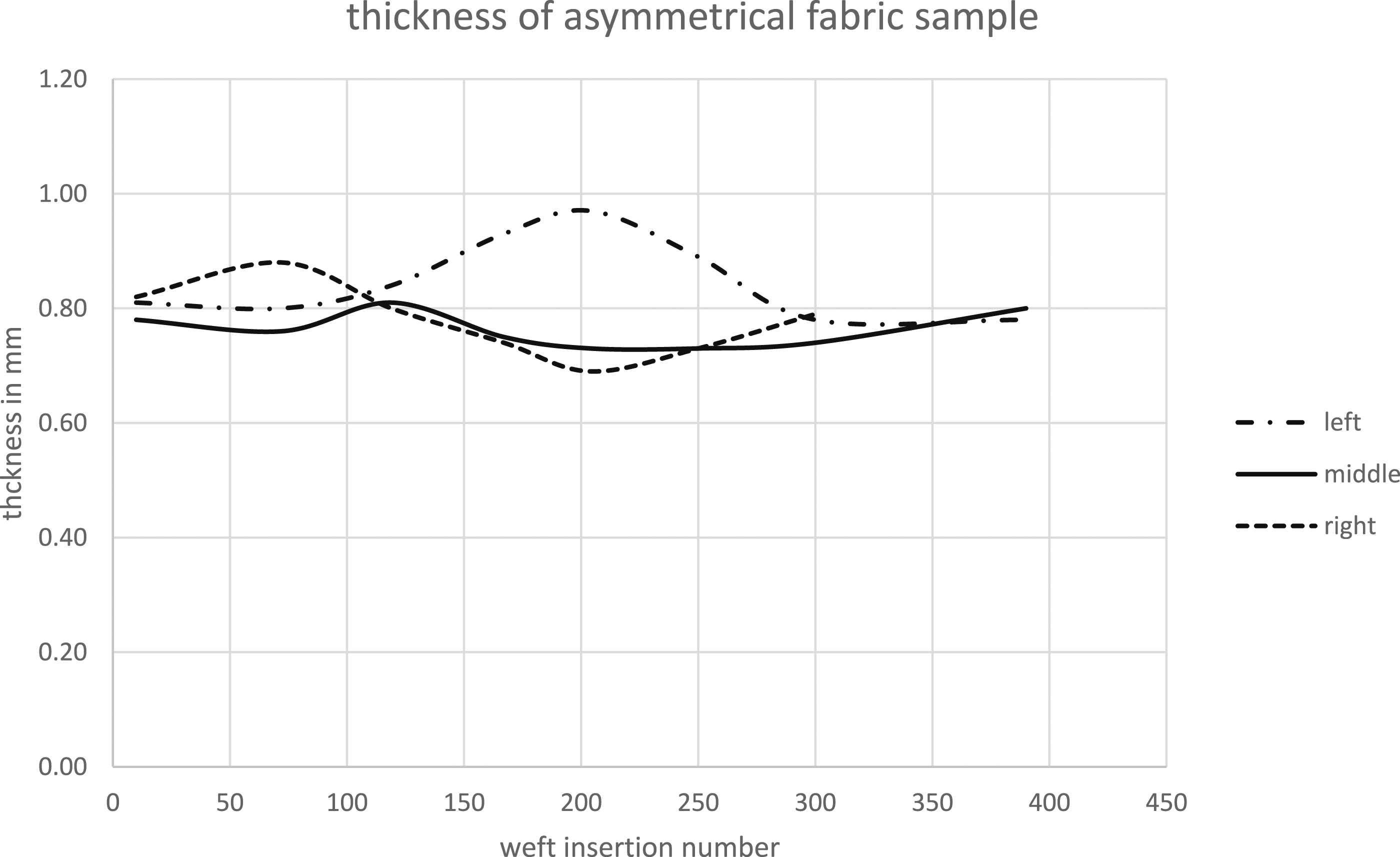
To ensure that the effect of the different square mass and the associated fabric thickness is more homogeneous along the fabric width, a more uniform distribution of the warp density along the fabric width should be aimed at for symmetrical fabrics. To ensure that this is also the case with asymmetrical fabric geometries, technical binding measures must be taken. For this purpose, different fabric weaves must be arranged along the fabric width so that not only the weft density but also the occupation factor can be adjusted via the calculation of the theoretical density factor (equations (1) and (2)).
Evaluation of the warp yarn tensions
To investigate the impact of process variables on fabric geometry and properties, the warp tension forces were monitored during fabric production of the symmetrical fabric sample. Specifically, the warp tension forces measured at the beginning of the fabric manufacturing, at maximum width reduction and at the end of the fabric. These measurements were taken both at the fabric's outer side and in the middle of the fabric. The VUTS yarn tension measuring system was used for this purpose, with 10 warp yarns selected to be in the same shed allowing to measure the warp yarn tension of the single shed. The measurements were conducted between the creel and the expansion comb spanning six weft insertions and starting at the lower shed position. The results clearly demonstrated that the warp tensile force in the lower shed was consistently lower than in the upper shed due to the shed geometry.
The measurement of the outer fabric area revealed that as the fabric width reduced, the averaged warp tensile force increased by 61.7% up to the reversal point at the smallest fabric width, after which it gradually decreased with the increasing fabric width (see Figure 17). Notably, the warp tensile force in the lower shed exhibited a significant increase. Overall, the average warp tension at the start of the fabric was 3.1 cN, at the reversal point 8.1 cN and at the end of the fabric 3.2 cN. In contrast, the measurement within the middle of the fabric indicated relatively constant warp tensile forces with minor fluctuations observed (see Figure 18). The change in warp tensile force in the outer fabric area was attributed to the different inlet angles of the warp yarns resulting from the fabric width changes. Although the expansion comb was implemented to compensate for this effect, some variations in the warp yarn angle remained between the weaving reed and the fabric take-up. These correlations are further detailed in the following section. Warp tension of outer warp yarns of the fabric. Warp tension of middle warp yarns of the fabric.

Evaluation of the warp yarn angle
Due to the dynamic adjustment of fabric width in the weaving process, the inlet angle of the warp yarn undergoes changes as it progresses towards the fabric formation zone along with alterations in the warp yarn angle within the finished fabric between the reed and the fabric take-up. These evolving angles induce lateral forces from the warp yarns onto the weaving reed. These lateral forces become apparent through the application of lateral force on the reed bars, thereby altering the gap distances of the reed. Consequently, a discrepancy arises between the resulting fabric width and the reed's adjustment positions. To assess the impact of these lateral forces on the reed gap positions, measurements of the warp yarn angle were conducted during fabric production. This involved determining the angles between the installed expansion comb and the reed, as well as between the reed and the fabric take-up.
The measurement of the inlet angle for each warp yarn was conducted simultaneously with the measurement of warp yarn tensile forces. This involved measuring the angle of the warp yarn between the expansion comb and the reed, as well as between the take-up and the reed. To measure the angle, the lateral distance between the vertically running line of the respective warp yarn and its actual path were recorded (see Figure 19). The measurement was taken at the outer of the fabric, specifically the 10th warp yarn from the left. The middle of the fabric showed no change in the running-in angle of the warp yarns located there. Figure 19 illustrates the hypothetical route of a single warp yarn. In this scenario, the fabric width diminishes using a flexible reed leading to a wider fabric width in the take-up, consequently causing an elevation in the warp yarn angle β. Hypothetical route of a single warp yarn.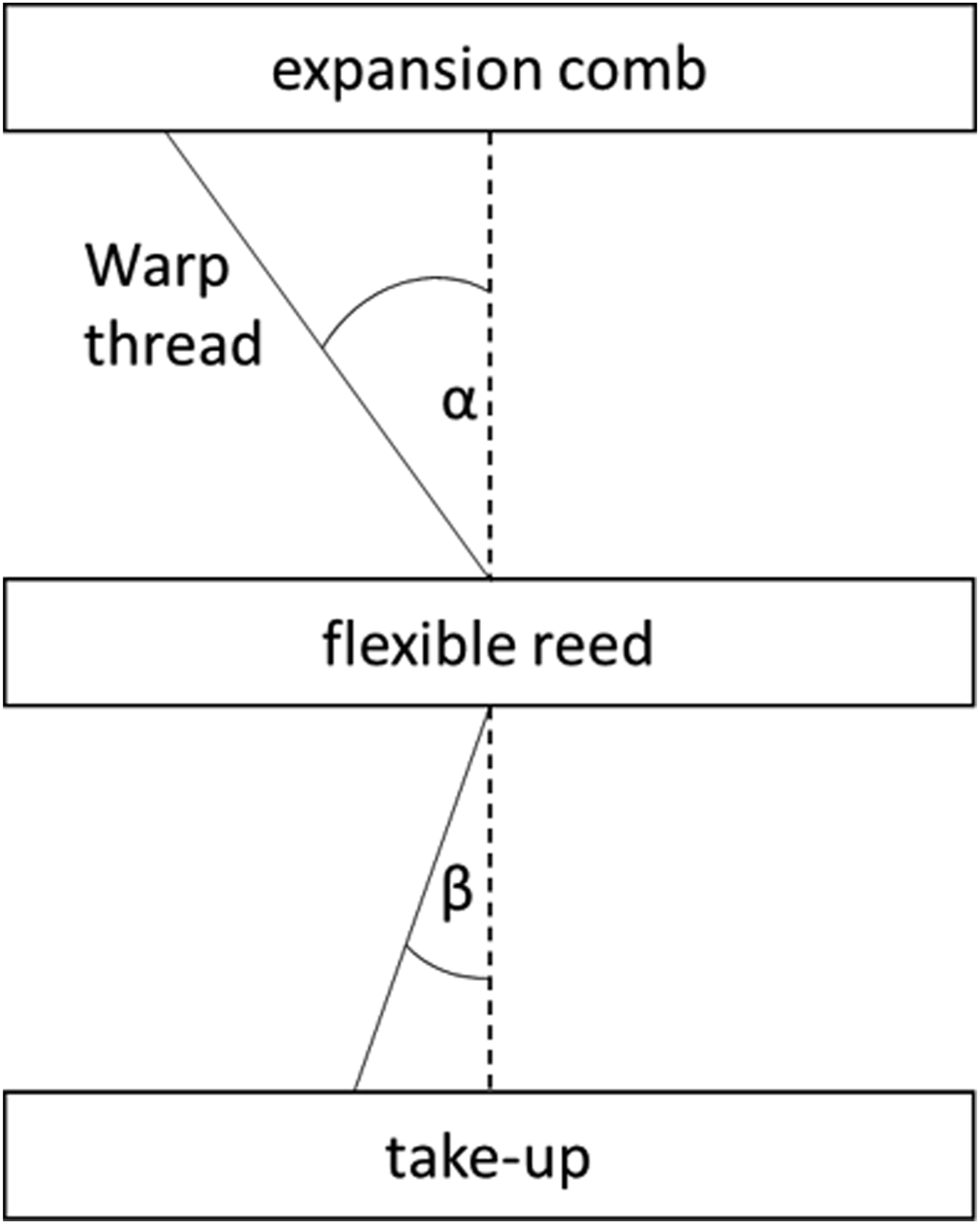
The outcome of the measurement of the warp yarn angle provided insight into the fabric width changes. The angle between the expansion comb and the reed remained nearly constant due to simultaneous width adjustments of both components (see Figure 20, angle between expansion comb and reed). However, the warp yarn angle between the take-up and the reed increased in parallel with the width reduction, reversing accordingly from the reversal point of the narrowest fabric width (see Figure 20, angle between reed and take-up). Subsequently, the warp angle became negative since the weaving reed contained fabric with a higher width while the take-up had the previously woven piece with a smaller fabric width. Measurement of the warp yarn angle during the fabric width change.
Discussion of the relationship between warp tension, warp angle and reed spacing
The measurement of the warp inlet angle between the fabric take-up and the reed is associated with an increase in warp tension force. As the angle increases up to the reversal point, the deflection at the respective reed bar also increases, resulting in higher warp tension force. This total lateral force of all warp yarns affects the adjustment of the spring-mounted reed spacing. After the fabric width has been widened again, the warp yarn angle between the reed and the take-up is reversed, leading to a lower warp tension force. This discrepancy can be attributed to the machine technology used. The warp yarns are fed through a passively braked creel. When the fabric width is widened after the reversal point, the outer side experiences a longer warp yarn length, which only becomes equal to the initial warp yarn length between the creel and the weaving reed after a considerable fabric length. As a result, the warp yarns in the edge areas experiences a lower warp yarn tensile force during the measurement.
To assess the influence of the warp yarn transverse forces on the reed fineness adjustment, the following relationship can be applied. For the considered reed gap the transverse forces of all warp yarns, starting from the middle, act on this reed gap. The transverse force increases with increasing warp yarn angle. The transverse forces of the warp yarns themselves counteract the adjustment process of the reed. The relationships between the forces during the adjustment of the flexible reed are presented in Figure 21. The following balance of forces exists. The calculation of the spring constant of the reed is shown in Figure 22. Resulting forces at certain reed bar. Calculation of the spring constant of the reed.


In the middle of the fabric, the average warp tensile force is 4.9 cN, the 10th warp yarn is 8.1 cN. This results in an increase of 3.2 cN with an equal increase in the angle between the take-up and the reed of 8.34°. Thus, assuming a linear relationship between warp yarn angle of 0.038 N/° and warp yarn tensile force of all transverse forces acting on the 10 reed gap (89 warp yarns) results in a total of
The total spring constant of the weaving reed forms a combination of a parallel and series switching (see Figure 22). The spring stiffness of one spring is 6.57 N/mm. This results in a total spring stiffness of
The total compressed distance is 175 mm. However, the reed bars are not compressed leadings into a resulting spring distance of 215.05 mm. This results in a total spring force of
In the reed gap, the equilibrium of forces shown in Figure 21 applies. Here, the spring force of the two springs with 13.14 N/mm acts against the total spring force of the reed bars below and that of the warp yarns. The frictional forces present were neglected due to insufficient recording. To check this relationship, the reed gap and thus the spring travel was measured once with and once without warp yarns for the present adjustment process. Without warp material, there is a compression of the reed gap of 2.7 mm, with warp yarns a distance of 2 mm was measured at the same reed gap. The initial height of the spring is 5.28 mm. This results in a spring force of

The calculation of the equilibrium of forces without warp yarns is:
The calculation of the equilibrium of forces with warp yarns is:
Thus, the deviation of the force equilibrium for the considered case with warp yarns is 1.07%, allowing a prediction of the resulting warp yarn densities in the respective areas. The deviation of the considered case without warp yarns is 7.4%. It should be noted that the adjustment of the weaving reed without warp yarns was carried out with an adjustment distance of 20 mm per rotation of the weaving machine, resulting in higher frictional forces between the reed bars and the shaft. Considering the theoretical distance between the reed bars based on the adjustment paths of the stepper motors, a reed gap distance of 2.9 mm is obtained, corresponding to a spring force of 31.27 N. This results in a deviation of 0.41% from the counteracting spring force.
The calculation of the lateral force effect resulting from the adjustment of the reed’s width reveals a hysteresis effect in the adjustment process. This implies that, following a reduction in fabric width, lateral forces counteract the spring elements' pressure forces when subsequently widening the fabric. Anticipating this deviation through the aforementioned calculation allows for proactive measures to enhance accuracy. Additional efforts are needed to tailor the control system accordingly.
Conclusion
This paper introduces a novel weaving reed that enables the production of width-variable fabrics on wide weaving machines, offering significant advantages in fabric reinforcement for FRP components. With this innovative solution, cutting processes can be eliminated as fabrics can be woven to have the desired contour directly. The developed weaving reed allows for flexible changes in reed spacing through external compensation forces, making it suitable for both symmetrical and asymmetrical fabrics. In contrast to traditional reeds, the newly devised reed provides enhanced flexibility in adjusting fabric width throughout the weaving process. This innovation, previously confined to narrow weaving machines employing a V-reed, represents a notable advancement. The width adjustment is achieved using stepper motors, and a program routine facilitates the calculation of adjustment paths for required fabric widths, ensuring precise control during fabric production. One notable innovation in the weaving process involves the orientation of the warp yarns within the fabric, deviating from the conventional perpendicular arrangement. In this unique approach, the warp yarns maintain a continuous trajectory, enabling the creation of a force-directed yarn path. This aspect proves especially crucial when it comes to enhancing the strength of FRP (Fibre Reinforced Plastic) components and fully unlocking their potential for lightweight applications.
To validate the effectiveness of this technology, symmetrical and asymmetrical fabric samples were developed and produced. The evaluation of the samples revealed the relationship between the developed machine periphery and various textile physical properties. The warp density, basis weight and fabric thickness were analysed at selected positions within the fabric samples. Additionally, the measurement of warp yarn tension forces and warp yarn intake angles during production allowed for an understanding of their impact on machine components and resulting reed gap distances, as evidenced by force scenario calculations. The calculated values can serve as a foundation for future endeavors focused on refining the control of stepper motors. This refinement aims to effectively compensate for the hysteresis effect.
The variations observed in warp density, fabric mass per unit area, and fabric thickness in samples with variable widths highlighted the importance of precise adjustments in weaving processes to achieve consistent fabric properties. Controlling fabric width changes during weaving proved to be a complex task, but further research and optimization in weaving techniques have the potential to enhance fabric quality and performance for practical applications. Additional inquiries into the warp yarn angle are warranted. Accordingly, exploring the implementation of a linear fabric take-up is recommended to minimize the angle between the reed and the fabric take-up. Furthermore, springs with a different spring stiffness must be examined. The novel weaving reed holds promise for industrial weaving machines, potentially replacing conventional reeds and revolutionizing fabric production for fibre-reinforced plastic components. As a result, it becomes possible to achieve machine speeds of up to 200 wefts per minute, a standard rate commonly observed in high-performance fibre applications. Achieving higher machine speeds faces a current limitation in the connection between the reed and the stepper motors, which relies on flexible shafts. Furthermore, there is a constraint on feeding warp yarns through warp beams. Moreover, there is a notable decrease in waste cuttings when compared to traditional manufacturing processes. For future work, a weft yarn length adapted to the fabric width is desirable. This allows near-net-shape zero waste fabrics to be produced. This reduction not only enhances material efficiency but also contributes to resource conservation. This aspect holds particular relevance in the context of providing fabrics for Fiber Reinforced Polymer (FRP) applications or architectural applications such as textile membranes. For instance, the production of near-net-shape fabric preforms enables the manufacturing of shell-shaped components, such as fan blades.
Footnotes
Acknowledgments
The authors express their gratitude to the “Arbeitsgemeinschaft industrieller Forschungsvereinigungen” for the financial support of the project IGF 21984 BR.
Declaration of conflicting interests
The author(s) declared no potential conflicts of interest with respect to the research, authorship, and/or publication of this article.
Funding
The author(s) disclosed receipt of the following financial support for the research, authorship, and/or publication of this article: The research project was carried out in the framework of the industrial collective research programme (IGF no. 21984 BR). It was supported by the Federal Ministry for Economic Affairs and Climate Action (BMWK) through the AiF (German Federation of Industrial Research Associations eV) based on a decision taken by the German Bundestag.