
Abstract
Textile reinforcements have revolutionized many industries, most of all aerospace, automotive and building. Due to its high performance and the significant increased lightweight potential, they have established themselves as an efficient and sustainable alternative to conventional materials. However, in view of the increasing demand of an ever growing population in contrast to a scarcity of resources and urge of material efficiency in the face of climate change, novel technologies for highly material efficient products in large-scale productions are required. In this regard, a major research field involves the multiaxial warp-knitting technique for the production of high performance textile preforms. In several steps, this technology has been further developed to enable the production of application-specific and bionic-inspired textile preforms, which are characterized by a force compliant and multi-material design. Yet the structural possibilities are still limited. This article presents a novel developed warp yarn manipulation system for multiaxial warp-knitting machines. The system enables the fabrication of 2D net-shape non-crimp-fabrics (NCF) made of up to 16 single warp yarns that specify by an alternating diagonally offset and overlapping edge-strand. This structure is suitable for the use as textile lattice girder for reinforcing concrete slab structures Hereby the developed warp yarn manipulation system allows highly various structural parameters of the 2D net-shape NCF for highest material efficiency and product variety. The technological development is discussed in means of the constructive and electronic control design as well as a specific application example for new net-shape reinforcement structures.
Keywords
Introduction
Constantly increasing demands and prices for production materials and energy resources, as well as the current obligation on the reduction of CO2 emissions, emphasize the need for sustainable lightweight constructions and resource-conserving production methods.1–3 Especially the building industry, which claims about 38% of the total CO2 emissions due to a high consumption of concrete
4
is looking for sustainable technologies. A change to more energy and resource efficiency as well as a growing awareness of sustainability is absolutely necessary. In the past two decades, resource-efficient carbon concrete, consisting of a corrosion-resistant textile reinforcement in combination with a significantly reduced concrete cover, has established itself in the construction industry as a convincing alternative to conventional steel reinforced concrete.5,6 Hereby the carbon concrete is particular convincing with its high load-bearing capacity of the textile reinforcement in addition to a required smaller concrete cross-section. These textile reinforcement structures, produced with the highly efficient multiaxial warp knitting technology,7,8 focus mainly on closed 2D non-crimp-fabrics (NCF) and grid-like NCF structures with regular grid spacing (Figure 1). Closed 2D NCF (a) and grid-like NCF structure with regular grid spacing (b).
For concrete reinforcement, grid-like structures are used due to a better concrete penetration. Hereby recent developments have improved the anchorage and bond behavior of the textile reinforcement structure in the surrounding concrete matrix through profiled9,10 or loop-shaped 11 structures. Consequently, the bond behavior between the reinforcement structure and concrete could be improved significantly, resulting in a high material efficiency of the textile reinforcement.
Independent of the material behavior, the structural demands on the textile reinforcement structures mainly result from the individual component designs. Due to standard guidelines, only limited textile architectures in the form of biaxial grid-like structures with regular grid are established.
12
However, in general, curves or various net-shaped structures with component dependent yarn paths are desired in order to achieve an agreement between the main tension curves of the component and the reinforcement directions of the textile structure.13–15 In order to achieve textile reinforcement structures with load and component dependent yarn path different manufacturing methods are possible. In order to achieve highest geometrical freedom, robot supported yarn placement or tailor fiber stich placement (TFP) are established manufacturing methods. In case of TFP single yarns are placed on a flat base fabric and fixed with an additional sewing thread during the fiber placement process16,17 (Figure 2(a)). For use in composites the water-soluble base fabric is removed and the remaining reinforcement structure consolidated using epoxy resin or thermoplastic matrices.
17
Robot supported yarn placement can be used for planar and three dimensional reinforcement structure by placing impregnated yarns on a support structure8,18 (Figure 2(b)).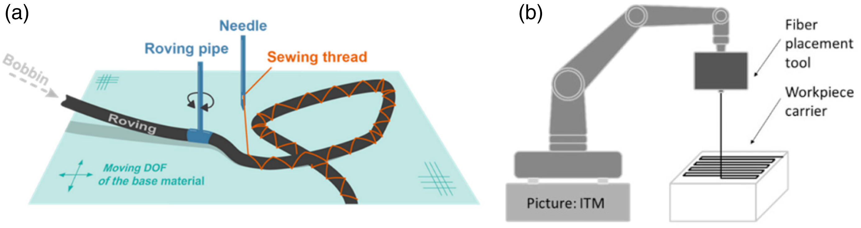
Although these manufacturing methods allow highest geometrical freedom and variation they are strongly limited in productivity due to single yarn placement. Therefor they are suitable for high-performance structures but not for general building applications with high volumes and quantities used.
In order to meet the demand for the building industry highly productive manufacturing methods on basis of the multiaxial warp knitting technology are needed. Therefor past research activities focused on the development of additional, modular systems to enhance the multiaxial warp knitting technology such as additional yarn feeding systems, 19 impregnation and consolidation systems, 20 profiling systems,9,10,21 shaping systems22,23 and yarn manipulation systems. 24 In order to produce net-shape NCF for concrete reinforcements focus of this study will be on yarn manipulation systems with an outlook on shaping systems.
In order to productively manufacture specific textile reinforcements structures using the multiaxial warp knitting technology first yarn manipulation systems have been developed, that allow the realization of customized grid-like structures with a structural and functional integration according to the force direction and formation of the component.15,24–26
A first warp yarn manipulation system for functional integration, which allows the limited manipulation of parallel warp yarns, was developed at the Institute of Textile Machinery and High Performance Material Technology (ITM) (Figure 2(b)).24,25 Hereby, manipulation width and degree of movement are restricted. For further variation of the warp yarn path, Cetex GmbH (Chemnitz, Germany) and Karl Mayer Technische Textilien GmbH (Chemnitz, Germany) developed the Variolay Technology, enabling a parallel manipulation of pre-fed warp yarns in a short distance to the warp knitting unit by fixating them on the closed NCF or base fabric (Figure 3(a)).26,27 A direct warp yarn manipulation in front of the warp knitting unit for the production without a base fabric is not possible. Hence, a fabrication of 2D net-shape NCF made of up to 16 single warp yarns with diagonal offset and an overlapping edge-strand for the use of textile lattice girders is not possible with the presented technologies.
Due to the more efficient use of the mechanical potential of the adapted textile grid structures, mayor improvements in material cost savings and material efficiency could be achieved. Yet these manipulation systems focus on a high precision of the manipulation within the grid structure or on top of the base fabric and are very limited in the degree of freedom, variety and quantity of the yarn manipulation possibilities.
2D net-shape structures like knitted textiles,
28
which enable a high structural variety, are not achievable with the multiaxial warp knitting technology. For the development of a highly productive and material efficient production process for 2D net-shaped NCF for a further use as textile lattice girder with various reinforcement paths and a high structural variety (Figure 4(b)) as known from steel lattice girders (Figure 3(a)), warp yarn path manipulation systems with a new scale of freedom of movement and quantity of independently manipulated warp yarns are required. Conventional steel lattice girder (a) and new textile lattice girder made of multiple warp yarns (each warp yarn has a specific color) (b).
Manufacturing method and materials
In this chapter the general manufacturing method, used materials as well as the constructive development process and electronic control design is presented in detail in order to design a yarn manipulation unit to produce net-shape NCF for concrete reinforcements.
Development of a yarn manipulation unit
For the fabrication of a textile lattice girder as concrete reinforcement structure (Figure 4(b)), a patented textile net-shape structure made of multiple warp yarns with alternating diagonally offset and overlapping edge-strands has to be produced.
29
In order to create a symmetric structure made of up to four overlapping yarns in the edge strand, a minimum spacing of 40 mm between diagonal offsets and a textile width of 300 mm up to 16 individual warp yarns have to be laid with an alternating diagonal offset angle α (e.g., 50° and 60°) in different directions and overlapping sections (e.g., four overlapping warp yarns), which form the edge-strands. Different laying systems of the multiaxial warp knitting technology enable up to four different laying angles (e.g., 0°, 90°, +45°, −45°), but due to the transport chain with a defined width for the fixation of the reinforcement yarns, the laying process is very limited in consideration of its structural variety.
2
A direct warp yarn manipulation in the warp knitting unit is not possible for several individual warp yarns. Furthermore, the fixed width of the conventional laying system and the following cutting of the edge strips result in discontinuous edge-strands as well as material inefficiency in regard of cutting for contoured structures.11,30 Especially for a continuous force transmission and high mechanical performance, a continuous reinforcement structure with continuous edge-strands made of overlapping warp yarns is highly desired.11,29 Yet, 2D net-shape NCF with alternating diagonal yarn courses with the offset angle α (Figure 5) and overlapping edge-strands can only be achieved by a warp yarn manipulation independent from the laying process and directly during the warp knitting process. Futhermore, no base material can be used for an open net-shape structure and therfore the warp yarn manipulation needs to be directly in front of the warp knitting unit. 2D net-shape NCF made of alternating diagonal offset warp yarns and overlapping edge-strands (left) with the offset angle α and detail of the edge-strand (right) with individually colored warp yarns; according to.
29

Materials
Materials for manufacturing of net-shape NCF. 9

Specific data about the material performance is presented in. 9 The detailed material use is mentioned in the individual sections of each manufacturing step.
Electronic control design of the manipulated warp yarn course
For the electronic description of the manipulated warp yarn course, a rectangular grid division based on15,24,25 was implemented. The warp yarn course pattern is hereby defined by a specific count of horizontal (x-direction) and vertical (y-direction) rectangular boxes with defined length and width. Figure 5 shows an exemplary yarn path for a 60° diagonal offset α.
Herby a repetitive pattern of four individual steps is described by defining the dimensions of the x- and y-box with an x-width of 20.0 mm and y-width of 20.17 mm resulting in a diagonal warp yarn offset of 300 mm in x-direction with a diagonal offset angle α of 60° (Figure 6). Exemplary description of the manipulated warp yarn course made of a box-system with defined x- and y-box count and the diagonal offset angle α.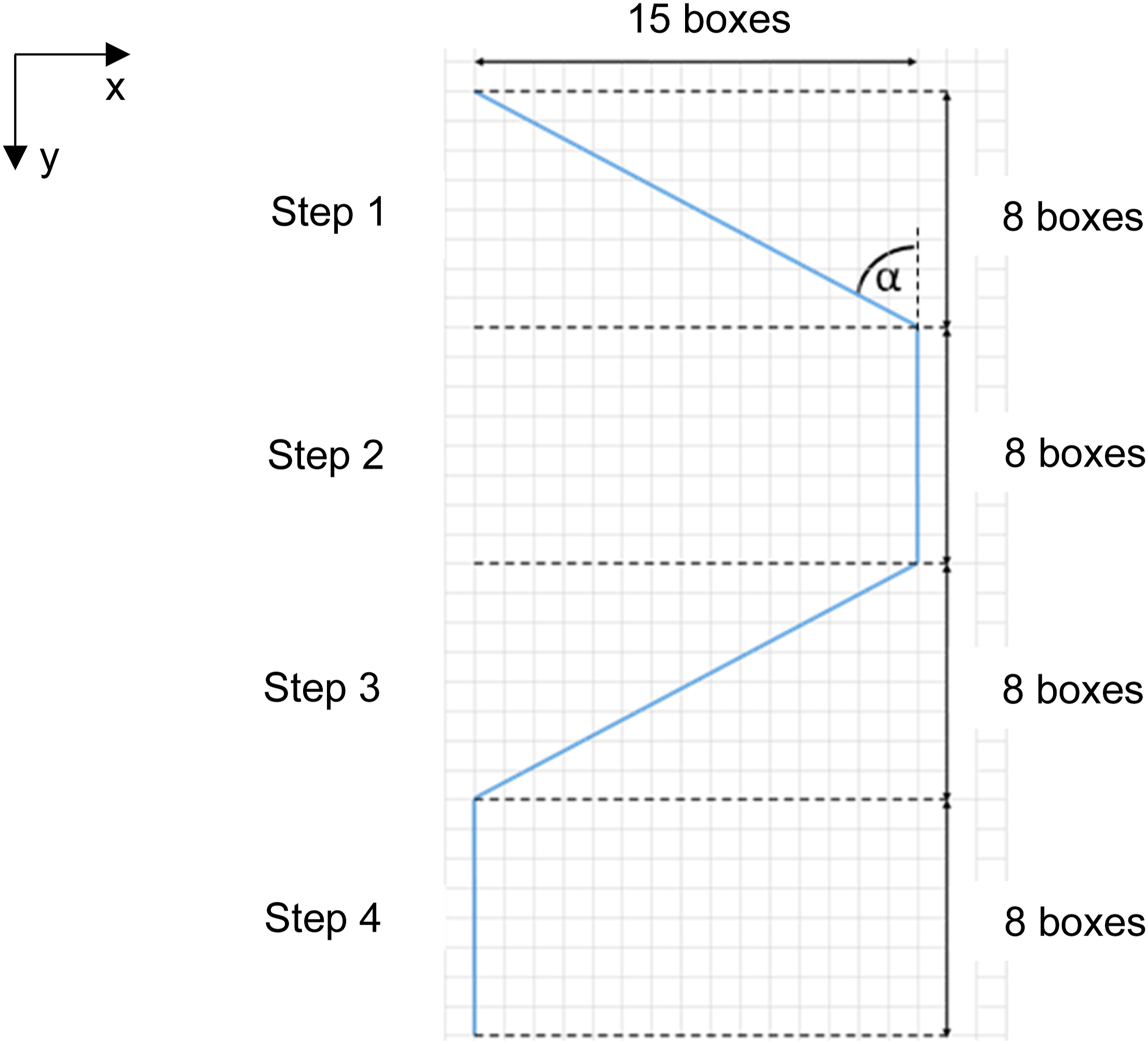
Grid-function for description of the manipulated yarn course with x-width of 20 mm and y-width of 20.17 mm for a resulting diagonally offset angle of 60°.

By changing the box dimensions, the diagonal offset angle α can be varied abundantly in a range of 1–90° in dependence of the production (up to 7 m/min) and offset speed (up to 2 m/s).
In order to create a continuous 2D net-shape NCF structure, several warp yarns are manipulated in a specific order. By overlapping 16 individual warp yarn courses with a defined diagonal offset in the y-axis, a repetitive structure is depicted (Figure 7). The slight deviation in the linear course at the edge-strand shows the overlapping warp yarn in the edge-strand. Exemplary 2D net-shape NCF structure made of multiple warp yarns with alternating diagonal offset and overlapping edge-strands.
For the electronic control of the warp yarn path manipulation, the y-distance between the manipulation and the warp knitting unit has to be considered. Due to limited installation space, a minimal gap between the manipulation and warp knitting unit is unavoidable. In order to manipulate a correct warp yarn course at the warp knitting unit, this gap and therefore increased distance has to be considered in the electronic control design of the warp yarn manipulation. The resulting delay of the manipulation course can be compensated with an overlength in x-direction of the course and an adaptable return step (Figure 8). Geometric correlation for the calculation of the overlength for compensating the gap between the manipulation and warp knitting unit by the offset angle α.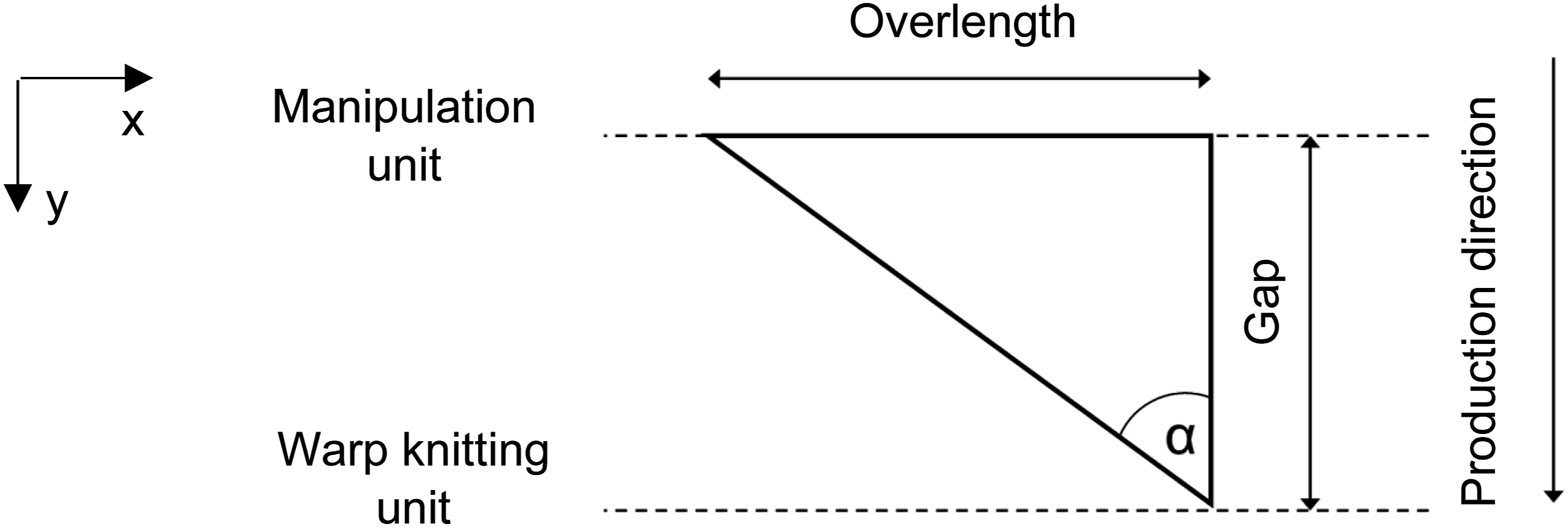
In case of a diagonal yarn course, the overlength is calculated by the following equation (1):
The exemplary and simplified control of eight manipulated yarn paths is depicted in Figure 9. Hereby only eight yarn paths are shown, because the symmetric design of the net-shape structure as well as the use of a symmetric yarn offset unit allows mirroring the manipulation along the center line, reducing the programming effort. Exemplary electronic control system for the warp yarn manipulation (each linear warp yarn manipulation unit with individual colour).
Design and integration of the manipulation unit
Conventional grid-like reinforcement structures for concrete applications are produced with the multiaxial warp knitting technology. Hereby reinforcement yarns are placed in defined angles (e.g., 90°, ±45°) in production direction through a laying system. 2 In order to ply the different layers of reinforcement yarns together, an additional knitting process is needed.7,31 As mentioned before, the conventional multiaxial-laying process cannot be used for net-shape reinforcement structures with continuous edge-strands and high structural variety. Therefor a new yarn path manipulation system was developed at the ITM, which enables the individual yarn path manipulation of up to 16 yarns during the knitting process without additional laying systems.
For the yarn manipulation, the yarns are guided in a linear offset unit (Figure 10). Through the overlaying of the linear offset in x-direction and the production speed in y-direction, the yarns course can be manipulated in any possible directions. Principle of the yarn manipulation system.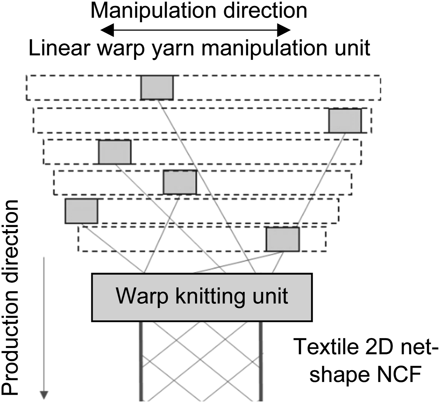
Each yarn needs its separate linear offset system, yet in case of symmetrical net-shape structures opposite offset systems can be used. Hereby two warp yarns are manipulated with the same linear offset system, where one warp yarn is manipulated in positive x-direction whereas the other warp yarn is manipulated in negative x-direction. In this case, 16 warp yarns can be manipulated with only eight linear offset systems (Figures 11 and 12). Especially when considering installation space, modularity and costs, the use of opposite linear offset systems for symmetrical net-shape structures is highly advantageous. According to changing demands, linear offset systems can be added. Concept of the warp yarn manipulation unit made of multiple linear offset systems. Newly developed modular warp yarn manipulation unit.

Results and discussion
In order to validate the technology and evaluate the efficiency of the produced 2D net-shape NCF the implemented production process as well as first studies on the load bearing behavior of the newly developed reinforcements structures are presented in the chapter. Furthermore a process chain for the production of 3D reinforcement structures is conceptualized. Yet, focus of this study will be the textile processing.
Technology validation
For the production of textile 2D net-shape NCF the newly developed warp yarn manipulation system is integrated into the High-performance Stitch Bonding Machine Malimo 14,024 with Multiaxial Weft Laying System (Figure 13) from the KARL MAYER Textilmaschinenfabrik GmbH (Chemnitz, Germany). High-performance stitch bonding machine malimo 14,024 with multiaxial weft laying system.
The movement of the offset system is transferred to the yarn by a yarn guiding system, which consists of hardened metal tubes (reduced bending) with an inner diameter of 3 mm and rounded edges for minimal yarn damage and friction. Using the long and friction optimized tubes, the yarn can be manipulated exactly and with low fiber damage in front of the warp knitting unit across a width of over 100 cm in addition to a minimal gap (50 mm) and therefore reduced compensating overlength (see Figure 14). Depiction of the developed warp yarn guidance system and the knitting unit.
The developed warp yarn manipulation system was used to produce 2D net-shape NCF structures made of 16 single carbon fiber heavy tows (CFHT) (Table 1). Hereby the overlapping warp yarn-segments in both edge-strands are plied together with a 11 dtex polypropylene warp knitting thread with a counterlaying tricot stitch pattern. For the formation of the structure, no further warp yarn or thread systems are used, except for the manipulated warp yarns and the warp knitting threads at the edge-strands (Figure 15). Production of the textile 2D net-shape NCF.
By adjusting the box-dimensions (see Table 2) in y-direction of the electronic control-grid, different diagonal offset angles could be realized (e.g., 20.17 mm for 60° and 22.93 mm for 50°; see Figure 16). Geometric variations (width – angle – overlapping roving in edge strand) of the net-shape reinforcement structure with a diagonally offset α of 50° (left) and 60° (right).
As depicted in Figure 16, the newly implemented warp yarn manipulation system enables the production of net-shape reinforcement structures with high geometric variety, reproducibility and productivity.
Experimental investigation of the load bearing behavior of 2D net-shape NCF
In order to evaluate the efficiency of the manufactured 2D net-shaped NCF as a concrete reinforcement structure, first investigation on the load bearing behavior have been performed by the Institute of Concrete Structures of the TU Dresden in a separate study which is presented in detail in. 32
Hereby yarn tensile test, single yarn pull-out test, tension tests (four-point bending test) and shear tests (three-point bending tests) on concrete embedded 2D net-shape reinforcement structures have been conducted.
The study 32 showed, that the developed 2D net-shape NCF are suitable for the use as material efficient concrete reinforcement structure and opens new design and application possibilities for precast concrete structures in hollow-core slab for ceiling but also wall elements. 33
Technology concept for 3D textile lattice girders for hollow concrete slab systems
For the use as a 3D textile lattice girder (3D reinforcement structure) (see Figure 14(a)) in precast hollow-core concrete slab structures (see Figure 14(b)), the developed textile 2D net-shape structure can be impregnated with a polymeric dispersion, shaped into a 3D-structure and consolidated in further production processes. In contrast to conventional steel reinforcements, which need an increased concrete cover for shielding from corrosion and environmental influences, the corrosion resistant carbon fibers with high tensile and load bearing capacities allow reduced concrete overlay and therefor thin slab structures with integrated cavities (hollow-core) for a maximum weight reduction. The new textile reinforced concrete slabs for the use in precast concrete ceiling or wall elements show an increased material efficiency, sustainability and new design possibilities in contrast to conventional precast concrete slab systems (Figure 17(c)) due to up to 40% reduced concrete use.
33

In order to produce 3D textile net-shape reinforcement structures for hollow-core slab systems, an impregnation, shaping and stabilization of the net-shape textile is needed. The proposed process chain is shown in Figure 18. Process chain for 3D-shaping and stabilization of 2D-textile.
Hereby the 2D textile structure is impregnated with a polymeric dispersion called TECOSIT CC 1000 from the company CHT Germany GmbH (Tübingen, Germany) on the impregnation machine Coatema Basecoater BC 32 (see Figure 19) from the Coatema® Coating Machinery GmbH (Dormagen, Germany) and shaped with a gentle forming unit into a 3D textile structure. Coating machinery basecoater BC32.
20

The impregnation is applied by a coating roll in a foulard coating tank. In order to achieve a high impregnation quality and therefore high inner bond by a uniform distribution of the impregnation, additional squeeze rolls press the impregnation into the textile structure. To guarantee a high inner bond and therefor highest tensile properties, a speezing pressure of 2 bar and production speed of 1 m/min is recommended. 20
The 3D textile is subsequently stabilized by heat, vaporizing the water and melting the polymer, creating a stiff 3D reinforcement structure in form of a textile lattice girder as depicted in Figure 20. Segment of a 3D textile lattice girder made of a 2D net-shape NCF.
A technology concept for the textile processing, shaping and stabilization for the fabrication of 3D-reinforcement structures for hollow concrete slab structures is presented in Figure 21. Technology concept for textile net-shape reinforcement structures for hollow slabs.
For the continous and industrial impregnation, shaping and stabilization of the textile net-shape structure a Base Coater BC 32 from the company Coatema Coating Machinery GmbH (Dormagen, Germany) with an additional integrated shaping unit can be used. For the precasting of the hollow concrete slab structure new formwork principles are needed.
Further application areas
The newly developed warp yarn manipulation system is suitable for a modular extension of the multiaxial warp knitting process in order to produce 2D net-shape NCF with continuous edge-strands, as well as grid-like and closed multiaxial structures (base fabric) with structural or functional yarn integration (e.g., sensors for structural health monitoring according to
35
; Figure 22(a)), according to the force direction or formation of the component. Furthermore it is possible to produce textile structures with variable widths (Figure 22(b)). A combination of textile net-shape NCF with variable widths and structural or functional yarn integration is possible as well. Textile net-shape NCF with variable widths (a) and multiaxial reinforcement structure with structural or functional yarn integration (b).
Conclusion and outlook
For the fabrication of 2D net-shaped NCF a novel warp yarn manipulation unit was developed, which enables a highly variable manipulation of up to 16 warp yarns with a new degree of movement alongside the multiaxial warp knitting technology. Furthermore an electronic control was developed for an easy programming and highly structural variety of the 2D net-shape NCF structures. In order to validate the developed warp yarn manipulation unit, different structures of 2D net-shaped NCF with a diagonal offset of 50° and 60° were produced. The developed system shows that it is suitable for the fabrication of 2D net-shape NCF made of up to 16 alternating diagonal offset warp yarns with overlapping yarns in continuous edge-strands on basis of the highly productive warp knitting process. These textile structures can be used for further production of 3D textile lattice girders as reinforcement structure of hollow-core concrete slab systems with higher material efficiency in contrast to conventional steel reinforced slabs. The efficiency of the produced 2D net-shape NCF as concrete reinforcement structure has been investigated in a separate experimental study.
In addition, the developed warp yarn manipulation unit can be used for the production of reinforcement structures with variable width as well as “customized” multifunctional grid structures with additional reinforcement yarns according to the demands and directions of force and formation. This enables a new degree for design, structural and functional integration, which results in reinforcement structures with new application areas as well as high material efficiency and mechanical performance. This technology contributes to the development of cost-efficient textile reinforced composites for concrete structures as well as thermoplastic applications with innovative characteristics concerning material efficiency, mechanical properties and customization.
Further studies will investigate the shaping process of textile net-shape structures as well as the structural behavior of textile reinforced hollow concrete slabs.
Footnotes
Declaration of conflicting interests
The author(s) declared no potential conflicts of interest with respect to the research, authorship, and/or publication of this article.
Funding
The author(s) disclosed receipt of the following financial support for the research, authorship, and/or publication of this article: The IGF research project 21556 BR of the Forschungsvereinigung Forschungskuratorium Textil e. V. is funded through the AiF within the program for supporting the “Industriellen Gemeinschaftsforschung (IGF)” from funds of the Federal Ministry for Economic Affairs and Climate Action on the basis of a decision by the German Bundestag. The Article Processing Charges (APC) were funded by the joint publication fund of the TU Dresden, the Medical Faculty Carl Gustav Carus, and the SLUB Dresden.