
Abstract
Carbon-fiber-reinforced polymer (CFRP) reinforcements offer high potential for resource-efficient and durable concrete structures due to their superior tensile properties and corrosion resistance. However, existing CFRP tendons and rope systems are limited in terms of bond performance, anchorage efficiency, bending capability, and applicability to filigree and modular concrete structures. This paper presents the development of novel CFRP rope structures based on preconsolidated, partially profiled carbon rovings combined with thermoplastic and elastomeric impregnation systems. The proposed rope concept features a spiral configuration of seven rovings, consisting of one central unprofiled strand and six surrounding profiled strands to enhance bond behavior. A laboratory-scale rotational manufacturing process is introduced, allowing controlled variation of spiral geometry and structural fixation. In addition, modified tensile testing and load introduction concepts based on segmented grouting were developed to enable reliable characterization of CFRP rope structures with increased diameters up to failure. Experimental investigations focus on tensile and bending behavior relevant to reinforcement and prestressing applications. The novel CFRP ropes achieve Young’s moduli between approximately 140 and 180 GPa and tensile strengths of about 2,350 MPa, exceeding a commercial epoxy-based reference by 10–30 %. Bending tests demonstrate that soft polymer-based impregnation enables small bending radii suitable for coiling and continuous production, while stiffer matrices provide higher axial stiffness at reduced flexibility. Overall, the results highlight the potential of thermoplastic-based CFRP rope systems for material efficient prestressing systems in combination with shaping, modular construction, demountability, recyclability, and future integration of sensor functionalities.
Keywords
Introduction
The global population is currently increasing by approximately 82 million people each year, 1 leading to a rapidly growing demand for new housing and infrastructure. Reinforced concrete remains the dominant construction material used to meet this demand. However, concrete production relies heavily on cement, the manufacture of which is highly energy-intensive and associated with substantial greenhouse gas emissions. On average, about 600 kg of CO2 are released per tonne of cement produced.2,3 Against this background, carbon-fibre-based reinforcement systems represent a highly promising alternative for future resource-efficient construction. Their inherent corrosion resistance allows for a significant reduction in concrete cover, while their outstanding tensile mechanical properties enable more material-efficient and durable structural designs.2,4
Textile reinforcements for carbon concrete are predominantly used in the form of grid structures with a biaxial configuration and are specified for the subsequent strengthening of existing structures in accordance with the general building authority approval Z-31.10-182. 5 These textile grids are characterized by an absolutely straight fiber alignment in combination with stiff impregnation agents (e.g., polyacrylate, PA, with thermoplastic properties), enabling efficient utilization of the high tensile performance potential of corrosion-resistant carbon fibers. For standard applications such as retrofitting and strengthening measures as well as simple plate-type precast elements, these geometrically simple grid structures have already become well established in the market.
However, due to the limited bond performance of conventionally smooth roving structures and the deformation limits required under service loads, tensile stresses in slack carbon reinforcements typically remain well below their full strength capacity.6,7 The production and application of prestressed concrete elements is one way of exploiting the full potential of carbon reinforcement, as this increases the degree of utilisation by a factor of 2 to 4 compared to slack carbon reinforcement.3,8 Only prestressing enables the efficient mechanical and economic use of high-strength carbon fibre-reinforced plastic (CFRP) tensile reinforcement, particularly in structures with large spans. 9
In civil engineering, various types of prestressable reinforcement systems, known as tendons, are used for this purpose. For applications in carbon concrete, carbon fibers are preferably processed into rods/strands, grids, wires, ropes, and laminates (see Figure 1).
In bonded prestressing systems, structures can be prestressed using appropriate anchorage solutions, such as clamping and wedge anchors, bonded or grouted anchorages, and loop or sling-type systems. 14
For space-saving, cost-efficient, and durable solutions, compact force- or form-locked anchorage systems with optional grouting are particularly advantageous, as they reduce manufacturing complexity, handling effort, material costs, and improve mechanical efficiency.6,14–16 Hereby, a segmented grouting approach adapted to the load distribution within the load introduction zone is particularly advantageous, as it allows stress concentrations to be reduced. 16
For prestressing, unidirectional wires or ropes have become established as tensile elements, as they can be handled similarly to steel tendons using compact, mechanical, and time-efficient anchorage systems, making them easier to use than planar grids or laminates. Depending on the application, the strands are twisted into bundles of 7, 19, or 37 strands arranged in a hexagonal rope configuration. Due to their high tensile strength and low density, carbon-fiber-based tendons offer excellent corrosion resistance and a significantly higher lightweight potential than conventional prestressing steel, achieving roughly twice the tensile strength at only one-fifth of the weight of comparable steel strands.
The Japanese company TOKYO ROPE is currently the only manufacturer worldwide that commercially supplies carbon-fiber-based strands and spiral ropes.17,18 These CFRP ropes consist of 7 to 37 bundled individual fiber strands, which are impregnated with an epoxy resin matrix prior to stranding.17,19
The strands are sufficiently flexible to be coiled and transported compactly. However, the stranding process—often not fully adapted to the material’s sensitivity to small bending radii—can reduce the strength of carbon yarns. In addition, their relatively smooth surface leads to insufficient bond performance in anchorage and load transfer zones, or requires higher prestressing levels. As a result, anchorage heads and load introduction zones are often similar in size to those used for steel reinforcement, requiring increased concrete cover due to the risk of splitting. 20 This diminishes the advantages of carbon reinforcement for slender, filigree concrete structures.14,21
An impressive example of the use of CFRP strands in slender load-bearing structures is the carbon concrete girders used for the roof of a primary school hall. 21 However, microcracks are observed particularly in the load introduction zones, resulting from the prestress transfer and the dense arrangement of tendons in existing systems. 20
An alternative approach for the efficient use of tendons is modular or segmented construction, where individual concrete precast elements are connected using unbonded prestressed tendons. 22 However, compact anchorage systems and efficient prestressing methods remain essential for practical implementation.
In summary, filigree, high-performance rope structures with short anchorage zones suitable for miniaturized anchorage systems and filigree load introduction zones are not yet available. As a result, the full material-saving potential of carbon-reinforced concrete with slim structures and reduced concrete cover cannot yet be fully exploited.
Yarn profiling technology
A promising approach to improving bond and anchorage performance through form-fit mechanisms, while accounting for the anisotropic material behavior of CFRP reinforcements, has been developed at the Institute of Textile Machinery and High-Performance Material Technology (ITM) at TU Dresden.23,24 Using a material-specific forming-based profiling process, consolidated carbon polymer yarns (i.e., carbon fiber strands or rovings) can be produced with a defined surface geometry without significantly impairing their tensile mechanical properties. At the same time, the introduced profiling results in a substantial enhancement of bond performance, increasing the bond capacity by approximately 500 % compared to unprofiled carbon polymer yarns.23,24
This paper presents a novel approach for the development of high-performance, filigree rope structures that are suitable for miniaturized anchorage systems, slender load introduction zones, and slim concrete members with reduced concrete cover. The proposed concept is based on the use of profiled carbon rovings to manufacture slender, processable (i.e., bendable) CFRP rope structures for prestressed carbon concrete applications. The focus of this contribution is on the presentation of the fundamental production concept, the resulting tensile properties, and modified tensile testing methodologies required to adequately characterize the novel rope structures. Investigations on bond behavior and anchorage performance will be addressed in subsequent studies.
Materials & methods
Fiber material
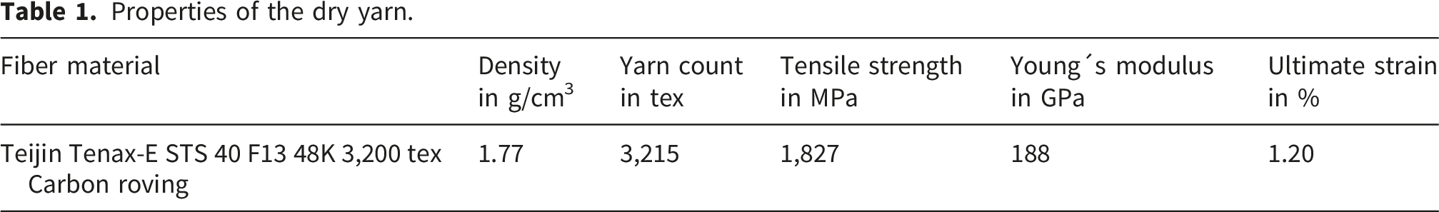
Properties of the dry yarn.
Impregnation material
Geometric properties of the roving and rope structure.


Scheme of individual fiber strand production (a) and spiral rope production made of bundled fiber strands (b) according to 19 .
Properties of the impregnation agents, data according to manufacturer’s specifications (Lefasol, Tecosit, Biresin).

1Mixing ratio in solid content; 100 g resin Biresin® CR84 and 28 g hardener Biresin® CH120-6.

Schematic production process of profiled carbon rovings and strands according to 22 .

Rope structure
The reference for the novel CFRP rope structure is the epoxy resin-based Tokyo Rope 6.1φ (7 individual strands with a diameter of 2.0 mm) strand, with a nominal diameter of 6.1 mm and tensile properties as specified in. 17
A new laboratory manufacturing approach is applied for the production of the novel thermoplastic CFRP rope structure. The rope is composed of seven premanufactured consolidated strands also called rovings that are rotated to form a spiral configuration (see Figure 5). The central strand has a circular, unprofiled geometry, while the surrounding spiral strands are profiled to enhance bond performance. An overview of the roving and rope geometry is given in Table 2. Schematic rope structure made of a circular center strand (dark grey), six spiral profiled strands (light grey) and a polymer matrix for structural fixation (blue) (a) and novel CFRP spiral rope (b).
After the rotation process, the spiral rope structure is stabilized using an aqueous polymer dispersion (TECOSIT CC 1000 or Lefasol VL 90) applied by drawing the rope through an open impregnation bath. The polymeric impregnation is introduced uniformly from all sides by means of multiple flexible absorbent rollers that are partly emerged in the impregnation level. Subsequent heating causes evaporation of the water and melting of the polymer, thereby fixing the rope geometry.
For manufacturing, the seven prefabricated and consolidated strands are fed linearly into a rotational unit (see Figure 6). This feeding concept enables the production of strands with a length of up to 2 m, which are manufactured discontinuously for an initial parameter study investigating the influence of rotational configuration and impregnation material on the bending and tensile properties. A gear set within the rotational unit allows the realization of different rotational configurations of the spiral rope structure (see Figure 7). Schematic set up of the laboratory linear rotational unit for stranding and rope production. Schematic set up of the gear sets for rotational unit for adjustment of the degree of rotation.

Following the rotation process, the rope is guided through an impregnation bath for the application of a polymeric dispersion. The pulling process is performed using a linear high-pitch threaded rod combined with clamping of the rope end. After a pulling length of 70 cm, the corresponding segment is subjected to infrared radiation for thermal treatment of the impregnation and structural fixation. Heating is carried out using infrared radiators (3 kW, OPTRON GmbH) operated at 50 % power for 2 minutes at 15 cm distance. By applying three successive cycles of segmented pulling and heating, each covering 70 cm, a CFRP rope specimen with a total length of approximately 2 m is produced for subsequent mechanical testing.
The different rotational configurations are realized by interchangeable gear sets (see Figure 7). Gear set I consists of gear 1 and gear 2, gear set II consists of gear 3 and gear 4, and gear set III consists of gear 4 in combination with the high-pitch threaded rod used for linear pulling.
Ratio of gear set I (gear 1 to gear 2):
Ratio of gear set II (gear 3 to gear 4):
Ratio of gear set III (gear 4 to high-pitch threaded rod):
Based on the characteristics of the high-pitch threaded rod, the clamping device is displaced by 25 mm per revolution of the threaded rod, corresponding to the thread pitch p. Accordingly, the linear displacement per revolution of the threaded rod can be calculated as the product of the pitch p and the transmission ratios of gear set I and gear set II.
Overview of the different spiral rope configurations.

The influence of the spiral pitch, expressed by the degree of rotation, is investigated in tensile tests, with a particular focus on Young’s modulus to identify potential structural elongation effects. Such elongation is disadvantageous in brittle concrete structures, where immediate force transfer to the tensile reinforcement is required.
Each spiral rope configuration was produced using the same individual rovings/strands, which were premanufactured and consolidated with TECOSIT CC 1000, but realized in two different variants of polymer-based structural fixation. One variant was fixed using a soft rubber-based styrene–butadiene rubber (SBR), while the second variant employed the stiffer acrylate-based Tecosit system. The influence of the structural fixation material is subsequently investigated in bending tests to derive a configuration suitable for coiling and continuous (“endless”) production of CFRP ropes intended for industrial applications with large span widths.
Shaping
To demonstrate the feasibility of subsequent thermoplastic shaping and to enhance anchorage in the tensile test setup, both ends of the cut tensile test specimens (450 mm in length) were profiled with a scaled-up tetrahedral geometry. For this purpose, a laboratory-scale shaping device was employed, consisting of two opposing profile elements analogous to the profiling unit used for the profiled rovings (see Figure 8). The specimen ends were placed in the shaping device, heated using hot air (450 °C at a distance of 10 cm for 20 s) and profiled at a profile element spacing of 8 mm. Setup for subsequent thermoplastic shaping with the profiling device (a) and profiled end of a rope structure (b); 1 – profiling element; 2 – rope end; 3 – support structure; 4 – screw system.
Tensile test
To evaluate the tensile properties of the rovings and the rope structure, tensile tests were conducted. For this purpose, two different testing methods were applied: a standard tensile test procedure for the consolidated rovings and a modified test setup specifically developed for the novel rope structures.
Since the consolidated rovings (fiber strands) and profiled rovings exhibit increased bending stiffness and tend to fail by fiber or yarn fracture due to wrapping effects, tensile testing is conducted in accordance with DIN EN ISO 10618 (see also Ref. 24). The test specimens are 450 mm long and the free gauge length is set to 200 mm. The ends of the profiled yarns are clamped using metal grips with a steel file-cut surface. For this purpose, individually impregnated rovings (unprofiled and profiled) are resin-embedded in the clamping area for defined load introduction zones (see Figure 9) and fixed between two pneumatically actuated steel clamps (50 mm × 60 mm) with a file-cut gripping surface at a clamping pressure of 35 bar. Figure 9(a) and (b) illustrates the clamping and load introduction principle, while Figure 9(c)) shows the corresponding test setup.
All tests are conducted using a Zwick 100 universal testing machine manufactured by ZwickRoell GmbH & Co. KG (Germany). The crosshead displacement rate is set to 3 mm/min, the pre-tension force to 10 N. The applied force is measured using a 100 kN load cell, while the elongation of the test specimen is determined by an optical laser-based measurement system consisting of two displacement sensors and reflective markers that are attached to the test specimen prior to testing.
For clamping the rope structures, a modified load introduction concept was required, as the rope diameter is approximately three times that of the individual rovings, which led to failure of the epoxy resin ends under high pneumatic clamping pressures. To address this issue, four new specimen mounting variants (variants 2–5) were investigated in addition to the conventional resin-molded ends (variant 1). These mounting concepts are based on the grouting principle used for CFRP tendons in prestressing applications and are specifically designed to reduce stress concentrations in the load introduction zone. The variants consist of metal blocks that are either drilled or milled and designed as a single block (variant 1), two half-shells (variants 4 and 5), or three segmented and bolted blocks with conical cavities (variant 3) (see Figure 10). These designs allow for easy handling and demolding and are attached to a mounting device in the tensile testing machine (see Figure 11). Variant 5 represents the most complex mounting configuration and is based on a segmented grouting principle for prestressing in accordance with.16,26 It was originally designed for CFRP tendons and ropes with larger diameters; however, in the present study it is employed for initial testing in order to enable tensile tests up to failure without slip. Tensile test setup (a) and schematic representation of the metal block mounting (b) for the load introduction and specimen handling.

For specimen preparation, the rope tensile specimen was positioned vertically in the cavity on one side, centered using a simple 3D-printed element, and cast with room-temperature-curing epoxy resin. After a minimum curing time of 12 hours, the procedure was repeated for the opposite end. (see Figure 12). Illustration of the tensile test specimen production (a) and single test specimen with mounting variant 2 (b) for the load introduction elements.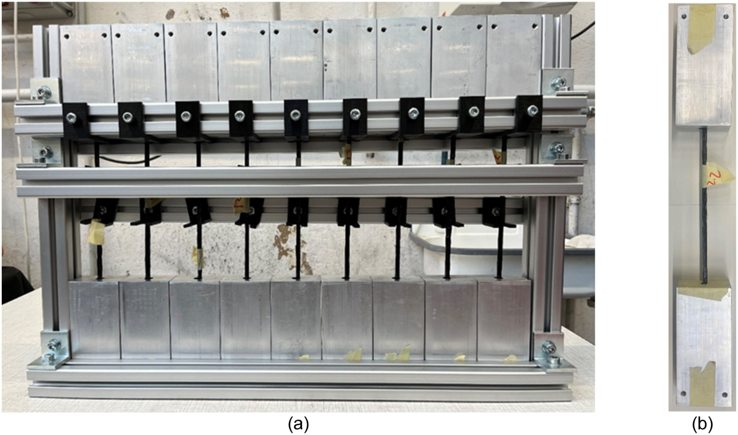
The length of the metal blocks was varied, as initial trials showed premature pull-out of the rope at loads exceeding 20 kN, well below the expected failure load. In order to contain the free gauge length of 200 mm, the tensile test specimens were enlarged according to the doubled mounting length. To eliminate slip, the rope specimen ends were additionally profiled as described in the section “Shaping.” The combination of profiled rope ends with clamping variant 2 showed an easy handling, installation, simple sealing for pouring of the epoxy resin and enabled the determination of Young’s modulus up to an elongation of 0.8 % (between 0 to 0.8 % elongation, and all tests aimed at measuring the elastic modulus were therefore conducted using this configuration (see Figure 11).
However, at loads of approximately 32 kN (ca. 80 % of the theoretically calculated breaking force of the seven individual rovings with a breaking force of > 6,000 N each
23
), slip of the rope specimens and pull-out from the epoxy-filled cavity still occurred. Consequently, variant 5 was developed after completion of the parameter studies and selected as the preferred configuration for determining the ultimate tensile strength of the rope structures up to failure (see Figure 13), enabling comparison with the Tokyo Rope reference. Tensile test setup with the mounting variant 5 (a) and rope specimen tested to failure (b).
Composite area calculation
To enable a meaningful comparison of the tensile properties between the novel thermoplastic rope structure composed of profiled rovings and the epoxy-resin-based Tokyo Rope reference (composite cross-sectional area of 22.7 mm2 according to the datasheet
17
), the composite cross-sectional area of the novel rope structure was determined. As the tetrahedrally profiled rovings exhibit a periodically varying cross-section, the effective area cannot be measured directly and was therefore calculated. For this purpose, the composite cross-sectional area of each individual roving/strand was determined based on a weight comparison between the impregnated rovings and the corresponding dry filament yarns, taking into account the calculated fiber volume fraction. The total cross-sectional area of the rope structure was then obtained by summing the areas of the seven individual rovings.

and
The composite area of the CFRP rope is calculated accordingly:
The resulting tensile strength of the CFRP rope structure using the composite area is calculated according to the following equation:
Young’s modulus is evaluated over the strain interval from 0.0 to 0.8 % elongation based on the following expression:
Bending test
Three-point bending tests in accordance with DIN EN ISO 14125 were conducted to determine the bending properties of the novel CFRP rope structure and to derive a parameter set enabling coiling and winding, thereby facilitating the continuous production of “endless” rope structures for large-span applications. For the estimation of the minimum damage-free winding diameter D_rope_min of the rope, the following expression is used:
For testing, the rope specimens were cut into 400 mm long segments and placed on the supports with a span length of 280 mm (corresponding to 40 times the rope diameter). A force is subsequently applied (pre-load of 1 N) perpendicularly to the top surface of the specimen at mid-span between the supports at a test speed of 10 mm/min. The applied load and the resulting deformation are recorded to determine the bending modulus and bending strength. The bending tests are performed using a Z2.5 “Zwicki Junior” testing machine from ZwickRoell GmbH & Co. KG (Ulm, Germany), as shown in Figure 14. Bending test setup at Zwick Z2.5 testing machine.
Results & discussion
Bending behavior
The results of the three-point bending tests, aimed at identifying a suitable spiral rope configuration for the continuous production of a coiled rope, are presented in the following diagrams (Figures 15 and 16). Herby for each configuration at least 5 specimens were tested an are represented with a single standard deviation. Breaking force of the different CFRP rope structure configurations. Deformation at Fmax of the different CFRP rope structure configurations.

The results indicate that the bending strength of the soft SBR-impregnated (Lefasol) rope configurations remains nearly constant at approximately 40 - 45 N, independent of the degree of rotation corresponding to spiral revolution lengths between 200 and 400 mm, when considering the standard deviation. The deformation at maximum load (Fmax) is likewise comparable for all configurations, amounting to approximately 40 mm (±8 mm) on average. Assuming an approximately uniform curvature, a deformation of 45 mm at a support span length of 280 mm corresponds according to equation (9) to a bending radius of about 1.0 m, which is well suited for continuous winding and appropriate handling of the rope structure. Consequently, when using the soft SBR impregnation, the degree of rotation within the investigated range has no significant influence on the bending behavior, while enabling a sufficiently small and practical bending radius.
In contrast, the stiff acrylate-based PA impregnation (Tecosit) exhibits a pronounced dependence on the degree of rotation. A high degree of rotation (spiral revolution length of 200 mm) results in the highest bending strength (approximately 60 N) combined with the lowest deformation at failure of approximately 13 mm (±2 mm) on average, leading to a stiff and brittle behavior comparable to conventional reinforcing bars and therefor unsuitable for coiling or winding. For lower and intermediate degrees of rotation (300 and 400 mm), the ropes show similar bending behavior, with bending strengths of approximately 38 N at deformations of around 28 mm (±2 mm) on average. This deformation corresponds to a winding radius of roughly 1.4 - 1.5 m, which is technically feasible but would result in challenging handling conditions. In particular, scaling the rope structure to larger diameters exceeding 6 mm would further reduce handling practicability.
Overall, the results demonstrate that soft SBR impregnation (Lefasol VL 90) is the most suitable option for structural fixation of the rope structure with respect to continuous production, coiling capability, and ease of handling of the novel CFRP rope systems.
Tensile behavior
The results of the tensile tests, conducted to assess the influence of the degree of rotation on the tensile properties and to identify a favorable CFRP rope configuration in comparison with the Tokyo Rope reference, are presented in the following diagrams (see Figures 17 and 18). Hereby, Young’s modulus and tensile strength are calculated based on the composite cross-sectional area of the CFRP rope structures. The corresponding data for the Tokyo Rope reference are taken from.
17
For each configuration at least 5 specimens were tested and the single standard deviation is illustrated in Figure 17. Young`s Modulus of the different CFRP rope structure configurations and the Tokyo Reference acc. to
17
. Tensile strength of the novel CFRP rope structure and the Tokyo Reference acc. to
17
.

As described previously, the tests for determining Young’s modulus were conducted using mounting variant 2, which enabled slip-free measurements up to an elongation of 0.8 % for a minimum of 3 specimens for each configuration. Based on the results of these tests, a favorable CFRP rope configuration was selected for subsequent tensile testing up to failure. These ultimate tensile strength tests were then performed using mounting variant 5, which was specifically designed to ensure reliable load transfer and to allow measurement of the tensile strength of the rope structures up to failure.
The evaluation of the results shows a clear dependence of Young’s modulus on the degree of rotation for a given impregnation system. For both impregnation agents, Young’s modulus decreases with decreasing degree of rotation (i.e., increasing spiral revolution length). In the case of the soft SBR-based impregnation, the highest Young’s modulus of approximately 150 GPa (±30 GPa) on average is obtained at a high degree of rotation, while the lowest average value of about 140 GPa (±25 GPa) is observed at a low degree of rotation, corresponding to a reduction of roughly 7 %. For the stiff PA-based Tecosit impregnation, a more pronounced effect is evident: Young’s modulus decreases from approximately 180 GPa (±5 GPa) on average at a high degree of rotation to about an average of 145 GPa (±15 GPa) at a low degree of rotation, representing a reduction of around 20 %. The high standard deviations that occur are supposed be reduced in future by a more automated manufacturing process.
A comparison of CFRP rope configurations with different impregnation agents at identical degrees of rotation further highlights the influence of the matrix system. For high, medium, and low degrees of rotation, the Tecosit-impregnated CFRP ropes consistently exhibit higher Young’s moduli—by approximately 10 - 20 %—than the corresponding soft SBR-impregnated configurations, largely independent of the rotational configuration. When compared to the Tokyo Rope reference with a Young’s modulus of 122 GPa according to, 17 all novel CFRP rope configurations demonstrate a significant increase in stiffness, with Young’s modulus values exceeding the reference by approximately 10 % to 30 %.
Considering both the bending behavior and the tensile performance in terms of Young’s modulus, the soft SBR-impregnated CFRP rope with a low degree of rotation was identified as the most favorable configuration. To evaluate its tensile strength, a single tensile test (one single specimen) up to failure was conducted to obtain an initial assessment of the mechanical properties, using the complex mounting variant 5 (see Figure 18), which allowed reliable load introduction and prevented slip during testing up to failure. The data of the reference is represented according to the manufacturers data sheet.
The results indicate that the novel CFRP rope structure achieves a tensile strength of approximately 2350 MPa, corresponding to an increase of about 10 % compared to the Tokyo Rope 6.1φ reference (2137 MPa acc. to 17 ). Although the Tokyo Rope reference employs an epoxy resin matrix—known for high tensile performance in CFRP systems— the newly developed spiral rope concept based on preconsolidated individual rovings, with and without surface profiling, shows improved tensile properties. These results were obtained using a linear and discontinuous laboratory-scale manufacturing setup, highlighting the potential of the proposed approach despite the early development stage.
Conclusion & outlook
This study demonstrates the technical feasibility and high potential of novel CFRP rope structures based on profiled, preconsolidated rovings for reinforcement and prestressing applications in carbon-reinforced concrete. The results show that, even at an early laboratory development stage with a linear and discontinuous production setup, the proposed spiral rope concept achieves superior tensile stiffness and strength (+10 %) compared to the state-of-the-art Tokyo Rope reference, while also providing significantly improved bending capability when combined with soft thermoplastic impregnation systems e.g. SBR. In particular, the use of thermoplastic matrix systems enables subsequent shaping and controlled bending, which opens up new possibilities for modular structural concepts, demountable anchorage solutions, and enhanced recyclability compared to conventional thermoset-based CFRP tendons. These properties are especially relevant for modular construction systems, slim load introduction zones, and sustainable infrastructure concepts.
In addition, the study highlights the strong potential of the developed, modified tensile testing methodology and segmented grouting-based mounting concepts for the reliable characterization of CFRP tendons and rope structures with larger diameters. The investigated grouting concepts, inspired by prestressing applications, allow stress peaks in the load introduction zone to be reduced and enable slip-free tensile testing up to failure, providing a robust basis for future experimental investigations.
Future work should therefore focus on systematic studies of tensile behavior, bond performance, and load-bearing capacity in concrete, including pull-out tests, prestressing force transfer, and load introduction experiments in real concrete elements with increases specimen number for statistical validation. Further investment is needed to develop a continuous, industrial-scale production line for spiral rope structures, enabling scalable manufacturing and consistent quality in terms of rotational control, uniform impregnation, and continuous, damage-free coiling over industrial production lengths of several hundred meters. The presented concept offers broad flexibility for the use of alternative fiber materials such as basalt, glass, or hemp fibers, as well as different thermoplastic or hybrid impregnation systems, allowing adaptation to specific structural, economic, and sustainability requirements.
In future studies, larger rope and strand configurations will also be investigated. This includes increasing the diameter of the individual strands as well as developing multilayer rope structures with an extended number of filaments, such as 19-strand configurations. The objective is to assess the scalability of the proposed concept and to systematically evaluate the mechanical behavior, manufacturability, and suitability of these larger structures for highly loaded applications.
Moreover, the integration of sensor materials into the rope structures represents a promising pathway toward smart tendons and intelligent concrete elements with prediction of maintenance intervals and service life time. Such sensor-integrated CFRP ropes could enable real-time stress monitoring, detection of prestressing losses over time, and structural health monitoring at both the tendon and component level. Overall, the developed rope concept, production approach, and testing methodology lay a strong foundation for further research and development toward highly efficient, durable, and intelligent reinforcement and prestressing systems for next-generation concrete structures.
The developed CFRP rope structures offer a wide range of potential applications in lightweight and resource-efficient civil engineering. Promising fields of application include filigree bridge structures for pedestrians and cyclists with span lengths of up to approximately 12 m, as well as lightweight bridge systems for vehicular traffic with spans of up to 20 m. Due to their high tensile performance, corrosion resistance, and reduced concrete cover requirements, the ropes are particularly suitable for slender, material-efficient structural elements and modular construction concepts. Beyond bridge engineering, further applications include filigree load-bearing structures for agri-photovoltaic (agri-PV) systems, lightweight roofing and canopy structures, and other infrastructure elements where low self-weight, durability, and efficient force transmission are essential.
In addition, the CFRP rope structures offer significant potential for subsequent (retrofitted) prestressing, enabling the strengthening and functional upgrading of existing structures. This approach is particularly attractive for bridges and filigree concrete elements, where prestressing can be applied after installation to increase load-bearing capacity, control deflections, and extend service life without major structural intervention. The feasibility and structural benefits of such retrofitted prestressing concepts using CFRP rope systems in combination with smart textile reinforcement structures by means of multisensory integration will be investigated in the framework of the Cluster of Excellence CARE “Climate-Neutral and Resource-Efficient Construction” at TU Dresden and RWTH Aachen University.
Footnotes
Funding
The authors disclosed receipt of the following financial support for the research, authorship, and/or publication of this article: The research project 03LB3092D is funded by the Federal Ministry for Economic Affairs and Energy on the basis of a decision by the German Bundestag. The Article Processing Charges (APC) were funded by the joint publication fund of the TU Dresden, the Medical Faculty Carl Gustav Carus, and the SLUB Dresden.
Declaration of conflicting interests
The authors declared no potential conflicts of interest with respect to the research, authorship, and/or publication of this article.