
Abstract
Composite materials are widely used in aerospace, automotive industry and medical equipment, where most of the structural parts are made of fiber laminates. Rotary braiding is one of the most important methods to prepare composite preforms. The ordinary rotary braided preforms have low porosity and dense yarns, but are single-layer structures after molding, which do not meet the needs of most applications. To solve the problem that traditional laminates are prone to delamination, this paper designs a flat cross-linked braiding process for the preparation of multilayer-interlocking composite panels. The carrier trajectory is analyzed, and the spatial coordinate system of the braided chassis is established by combining the effect of the end traction system on the morphology of the preform yarns. The numerical model of the preform is initially obtained by using cubic B-spline curve fitting, and an algorithm for gathering yarns towards the fabric center is proposed to optimize the numerical model. Experimental samples of flat cross-linked preforms are prepared according to the braiding process, and the reliability of the optimization algorithm is verified by comparing the yarn coordinates of the experimental samples with those of the optimized numerical model.
Keywords
Introduction
Fiber-reinforced polymer matrix composites have the advantages of high specific strength, high specific stiffness, good corrosion resistance, and are widely used in aerospace, rail transportation, medical equipment and other fields.1–3 In the past few decades, the demand for high-performance fiber composite laminates such as carbon fiber and glass fiber has grown rapidly. 4 As the reinforcement of composite materials, preforms play an important role in the mechanical properties of structures. 5
Flat braiding is one of the means to prepare preform panels, and the braiding angle can be adjusted to meet the requirements of structural parts. 6 However, the current braiding technology is still at the two-dimensional level, and the thickness of the preform needs to be increased by stacking to suit more complex applications, which makes the composite material susceptible to delamination, so a lot of research is focused on the three-dimensional (3D) braiding process. 7 Yordan6,8 introduced a 3D braiding machine with an equal number of horn gears in the horizontal and vertical directions. The yarn in the outer layer of the preform will pass through the middle layer into the inner layer to form a 3D structure, but there is a strict correspondence relationship between the number of horn gears and the number of horn-gear slots in this process, and the preform has a low fiber volume fraction and a large porosity. Meng et al. 9 divided the carrier track grooves into several types and built a model that can determine the carrier arrangement based on carrier motion characteristics, and this model helps engineers to design 3D circular braiding machines. Glessner and Kyosev 10 investigated the technique of braiding preforms with bifurcated structures, and structural parts with such characteristics have common applications in the medical field. Wang et al. 11 designed a novel multiaxial 3D preform braiding technique. The preform is a multi-layer structure, and bias layers can be added at any position in the thickness direction to make the structure rich and diverse. Du et al. 12 described a rotary three-dimensional braiding process and designed algorithms to solve the carrier arrangement problem for fabrics with multiple cross-sections.
With the rapid development of braiding technology, the requirement for composite materials to maintain stable performance under complex operating conditions has become increasingly important. Composite structural parts manufactured by the conventional process of design, machining and testing have a long production cycle and high cost, so a lot of research in recent years has focused on the finite element analysis of composite materials.13–16 Zhang et al. 17 developed a parametric representative volume element (RVE) model comprised of dry fibers and matrix for predicting the tensile modulus of 3D four-directional braided composites by integrating Matlab software and Abaqus software. Gideon et al. 18 established three unit cell models for cylindrical braiding and determined the damage limits of the three unit cell models in axial pressurization experiments by means of simulations and experiments. Melenka and Carey 19 developed Braid CAM software for designing braiding patterns including diamond (1/1), Regular (2/2), and Hercules (3/3) patterns, helping to increase the use of woven composites in engineering design. Hajrasouliha et al. 20 analyzed the reasons for the different braiding angles on a non-circular cross-section core mold, and based on this phenomenon the preform stiffness matrix was determined and finite element modeling was performed using the VUMAT subroutine to help predict the mechanical properties of braided composites.
This paper aims to design a flat cross-linked braiding process for the preparation of multilayer-interlocking composite panels. The numerical model of the preform is established based on the carrier motion trajectory, and the accuracy of the geometric model is verified by preparing flat cross-linked braided samples through experiments, which provides a theoretical basis for the subsequent work of predicting the mechanical properties of composite materials by numerical modeling.
Carrier arrangement of flat cross-linked braiding
Flat cross-linked braiding can be used to prepare multilayer-interlocking composite panels, which overcomes the disadvantages of traditional laminates that tend to delaminate. As shown in Figure 1(a), the mechanical parts of the flat cross-linked braiding machine are mainly composed of braided chassis, carrier, 4-slot horn gears, 5-slot horn gears and 6-slot horn gears. (a) Flat cross-linked braiding machine mechanical parts. (b) Initial position of carrier arrangement of flat cross-linked braiding machine. (c) Vary-trajectory mechanism.
Figure 1(b) shows the initial position of the carriers of the flat cross-linked braiding machine. Red carriers move along the red track, and blue carriers move along the blue track. Red and blue carriers move only on their respective tracks, so the braided preforms are plates with separate upper and lower layers. Set red No. 2 (green No. 2), red No. 21 (green No. 1), blue No. 2 (yellow No. 2) and blue No. 21 (yellow No. 1) as cross-linked carriers, which can be realized to cross the layers by means of vary-trajectory mechanisms at A, B, C, D, E, F, G, and H, so as to connect the two layers separated from the top and bottom to form a three-dimensional structure.
Figure 1(c) shows the two operating states of the vary-trajectory mechanism. The core component of the vary-trajectory mechanisms is the toggle, by controlling the toggle to swing up and down can change the direction of movement of the carriers. Take green No. 2 carrier in Figure 1(b) as an example to illustrate the operation mode of the vary-trajectory mechanism. Initially the toggle at D turns to the side of the 5-slot horn gear. Set the horn gear to rotate one slot as one step. After 8 steps, green No. 2 carrier is located at the position of red No. 6 carrier in Figure 1(b). At the same time, the toggle at D turns to the side of the 4-slot horn gear, and green No. 2 carrier changes its original trajectory and moves towards the 5-slot horn gear on the second layer. After 2 more steps, the toggle at D turns to the side of the 5-slot horn gear, the red track returns to its original state, and all red carriers continue to move according to the original track.
Figure 2 shows the trajectories of all carriers, it can be seen that the trajectories of different carriers partially overlap. The track of the red carrier as shown in Figure 2(a) can be achieved by controlling the toggles at B, D and G. The track of the blue carrier as shown in Figure 2(b) can be achieved by controlling the toggles at C, E and H. The tracks of No. 1 and No. 2 green carriers partially overlap with red and partially overlap with blue. The track of No. 2 green carrier as shown in Figure 2(c) can be achieved by controlling the toggles at D and E. The track of No. 1 green carrier as shown in Figure 2(d) can be achieved by controlling the toggles at F, G and H. No. 2 yellow trajectory is centrosymmetric with No. 2 green trajectory, as shown in Figure 2(e), and No. 1 yellow trajectory is centrosymmetric with No. 1 green trajectory, as shown in Figure 2(f). Carrier trajectories. (a) Trajectories of red carriers. (b) Trajectories of blue carriers. (c) Trajectory of green No. 2 carrier. (d) Trajectory of green No. 1 carrier. (e) Trajectory of yellow No. 2 carrier. (f) Trajectory of yellow No. 1 carrier.
From Figure 2, it can be seen that after 17 steps No. 2 green carrier and No. 2 yellow carrier move to layer 5 and layer 1 in Figure 1(b) respectively, and after 20 steps No. 1 green carrier and No. 1 yellow carrier move to layer 4 and layer 2 respectively, the cross-linked carriers interchange braiding tracks and complete the inter-layer connection of the yarns. In order to fully study the spatial structure within and between the layers of composite preforms, this paper takes the preform braided by 25 steps of carrier movement as the object for analysis, and the carrier trajectory at each stage are shown in Figure 3. Carrier trajectory at each stage.
Numerical analysis of preform structure
Establish the spatial coordinate system of the braided chassis
The numerical model of preforms helps to analyze and predict the mechanical properties of composite materials, which greatly reduces the experimental cost and production cycle of composite parts. The structure of the preform is determined by the flat cross-linked braiding process. The numerical model of the preform can be determined by establishing the spatial coordinate system of the braiding chassis and then fitting the yarn sampling points. If the coordinate system is established based on the braided chassis shown in Figure 1(b), the distance between the two braided layers of the numerical model is larger and does not match the reality.
Figure 4 shows the equivalent diagram of the carrier track. Since the preform is soft and easy to bend, the 5-slot horn gears at both ends of the red track can be rotated around the adjacent 4-slot horn gears to make the center points of all horn gears collinear. In steps 7 to 19, No. 1 green carrier rotates around the 5-slot horn gear of the third layer, which is not interlaced with other yarns, so it is equivalent to staying at a point at this stage. Although the trajectories of No. 2 green carrier and No. 2 yellow carrier intersect, they do not appear at the same time in the second and fourth layers. The overall trend of No. 2 green carrier trajectory is to the left and then to the right, the overall trend of the No. 2 yellow carrier trajectory is to the right and then to the left, and the green track of the third layer is located to the right of the yellow track, so the two yarns do not intersect. Equivalent diagram of the carrier trajectory.
According to the above analysis and combined with Figure 4, a braided chassis coordinate system is established as shown in Figure 5. The length of each grid side is Coordinate diagram of the braided chassis.
Spatial trajectories of yarns
It can be seen from Figure 5 that the position of each carrier can be represented by coordinates. Taking the initial position of the No. 1 red carrier as the reference, the coordinates that the red trajectory passes through are


Taking the initial position of the No. 1 blue carrier as the reference, the coordinates that the blue trajectory passes through are


It can be seen from Figure 1(b) that No. 2 and No. 21 red carriers are replaced by No. 2 and No. 1 green carriers respectively, and the process of collecting the X-direction coordinates of the yarns carried by the remaining 21 carriers is shown in Figure 6, which shows that each group of yarn contains 26 coordinates. Similarly, the Y-direction coordinates of red yarns and the sampling point coordinates of blue yarns can be derived. Acquisition process of red yarn X-direction coordinates.
The coordinates that the No. 1 green carrier trajectory passes through are


The coordinates that the No. 2 green carrier trajectory passes through are


The coordinates that the No. 1 yellow carrier trajectory passes through are


The coordinates that the No. 2 yellow carrier trajectory passes through are


The Z-direction coordinates of the yarn sampling points are

The structure of the preform is related to a. If the yarn radius is set to r, it can be seen from Figure 5 that Yarn trajectories of the green No. 2, green No. 1, yellow No. 2 and yellow No. 1 carriers. (a) Yarn sampling points. (b) Connect adjacent sampling points with short line segments.
Combining equations (1a)–(7) and using Matlab software to connect the sampling points of each yarn, the yarn folded trajectories shown in Figure 8 are obtained. It can be seen that since the adjacent sampling points are connected by means of short line segments, the short line segments before and after each sampling point will form an angle, which does not correspond to the actual smooth yarn. Yarn folded trajectories of flat cross-linked braiding.
Yarn trajectory B-spline curve fitting
The folded yarn trajectories obtained by connecting sampling points with short line segments are not smooth, and this paper uses B-spline curve fitting to simulate the yarn trajectories of flat cross-linked braiding. The B-spline curve has the advantage of lower polynomial order and the ability to modify the local features of the curve as needed. The general expression of the B-spline curve is


According to equations (8a) and (8b), the higher-order B-spline basis functions are determined by the lower-order B-spline basis functions. In order to meet the fitting accuracy and not to consume too much computational resources, the yarn trajectories are fitted with cubic B-spline curves, that is,


The first four consecutive sampling points of the carrier are taken as the control points of the fitted curve, and the node vector is set as

According to equation (1) and Figure 6, the coordinates of the first four sampling points of No. 1 red carrier can be determined. Substitute the coordinates, equations (9) and (10) into equation (8) to obtain the first segment fitted trajectory of No. 1 red yarn. The fourth to seventh sampling points are used as control points for the second fitted trajectory. And so on to calculate the fitted trajectory of the whole yarn as shown in Figure 9(a), and the fitted trajectories of all yarns as shown in Figure 9(b). Let the yarn cross-section be circular, and take the yarn trajectory shown in Figure 9(b) as the centerline, and scan it with a circle of radius r = 2.5 mm to obtain the numerical model of the preform as shown in Figure 9(c). Cubic B-spline curve fitting numerical model of the preform. (a) Fitted trajectory of No. 1 red yarn. (b) Fitted trajectories of all yarns. (c) Numerical model of the preform.
After cubic B-spline curve fitting, the spatial trajectory of the yarn is smoother than the folded trajectory formed by connecting only the sampling points. The red and blue braided layers of Figure 9(c) are separated from each other, and the green and yellow yarns connect the two braided layers to form a 3D structure. However, the numerical model of the preform has the problem of large gaps between the yarns, while under the action of the end traction system, the internal yarns of real braided fabric contact each other and the gaps are small.
Numerical model optimization of the preform
According to Figure 5 and Section Spatial trajectories of yarns, the yarn spacing of the numerical model of the preform is determined by the edge length
From the coordinate diagram of the braided chassis in Figure 5, it is clear that the large coordinate spacing of each carrier step is the root cause of the non-compact fabric structure. Under the action of the end traction system, the yarn carried by the carrier has a tendency to tighten towards the center of the braided chassis until all yarns are in contact with each other, as shown in Figure 10. Yarn tightening trends.
In the numerical simulation of preforms, the relationship between yarns have three cases: spacing, contact, and interference. Contact is the ideal state, and also the goal of preform numerical model optimization. Figure 11 shows the motion vector diagram of yarn spacing and interference states. When the yarns are in the spaced state, the center Motion vector diagram of yarn spacing and interference states. (a) Spacing. (b) Interference.

When the yarns are in the state of interference, the center

According to equations (11) and (12), the distance

The numerical model of the preform shown in Figure 9(c) is divided equally into
According to the above steps, the trajectories of all yarns are obtained, and then scan them with a circle of radius r = 2.5 mm to obtain the optimized numerical model of the preform, as shown in Figure 12. Compared with the pre-optimized model shown in Figure 9(c), the distance between the two braided layers and the gaps between yarns are smaller, so the preform is more compact and more realistic. Optimized numerical model of the preform.
Experiment verification
To further investigate the accuracy of the optimized numerical model of the flat cross-linked braided preforms, yarns with cross-sectional radius r = 2.5 mm are used as braiding yarns to prepare the flat cross-linked preforms as shown in Figure 13(a). Due to the small variety of yarn colors, white yarns were used as cross-linked yarns instead of the green and yellow yarns in Figure 12. Experimental samples and numerical models of flat cross-linked braided preforms. (a) Experimental samples. (b) Preform slicing solution.
In order to verify the consistency between the experimental samples of the preform and the numerical model, the braided yarn I, II and cross-linked yarn III, IV, V, VI shown in Figure 13(b) are taken as the research objects. Since the braiding machine traction system can precisely control the traction speed, the yarn cross-sectional center coordinates of the preform and the numerical model are the same in the Z-direction. Divide the preform and numerical model into 41 groups of slices along the Z-direction, and the X-coordinates and Y-coordinates of the cross-sectional centers of the yarn I, II, III, IV, V and VI in all slices are measured, as shown in Figures 14 and 15. X-coordinates of yarn cross-section centers. (a) X-coordinates of yarn I. (b) X-coordinates of yarn II. (c) X-coordinates of yarn III. (d) X-coordinates of yarn IV. (e) X-coordinates of yarn V. (f) X-coordinates of yarn VI. Y-coordinates of yarn cross-section centers. (a) Y-coordinates of yarn I. (b) Y-coordinates of yarn II. (c) Y-coordinates of yarn III. (d) Y-coordinates of yarn IV. (e) Y-coordinates of yarn V. (f) Y-coordinates of yarn VI.

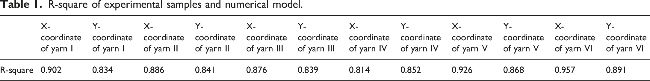
The consistency between the experimental samples of the preform and the numerical model is verified by the coefficient R-square, which is given by

R-square of experimental samples and numerical model.
Conclusion
In this paper, a flat cross-linked braiding process is designed for the preparation of multilayer-interlocking composite panels, which overcomes the disadvantages of traditional laminates that are prone to delamination. The carrier motion mechanism and vary-trajectory mechanisms for flat cross-linked braiding are described, and the trajectory of the carrier under each stage is plotted. The carrier motion law and the effect of end traction system on yarn morphology are analyzed, and the spatial coordinate system of the braided chassis is established. The coordinates of yarn sampling points are calculated, and the smooth yarn trajectory is fitted using cubic B-spline curve. It is found that the numerical model of the preform has the problem of large yarn gaps, based on which an algorithm is proposed for gathering yarns towards the fabric center. By extracting the yarn coordinates of multiple cross-sections of the preform and substituting them into the optimization algorithm, a numerical model with compact structure and low porosity can be obtained. Experimental samples of flat cross-linked preforms are prepared according to the braiding process, and the determination coefficient R-square of the horizontal and vertical coordinates of yarns in the experimental samples and the numerical model are calculated. The results are all greater than 0.8, which proved that the optimization algorithm is accurate and reliable. It provides guidance for the subsequent use of numerical model simulations to predict the mechanical properties of fabric and thus reduce experimental costs.
Footnotes
Declaration of conflicting interests
The author(s) declared no potential conflicts of interest with respect to the research, authorship, and/or publication of this article.
Funding
The author(s) disclosed receipt of the following financial support for the research, authorship, and/or publication of the article: This work was supported by the Shaoxing City Industrial Key Technology Tackling Plan Project (2022B41009), and the Scientific Research Starting Foundation of Shaoxing University (13011001002/207).