
Abstract
When the direct cabling machine produces cord, the active yarn feeder is usually used to control the balloon shape to reduce the energy consumption in the process of twisting. In order to rationally allocate the resources in the production workshop of direct cabling machine, the work proposed a prediction method of energy-consumption reduction for direct cabling machines based on balloon theory. The energy consumption of direct cabling machine with different balloon configuration parameters can be obtained. The prediction method consists of three main steps: (1) Analyze yarn force under the high velocity based on yarn balloon kinematics. (2) Take the energy consumed by the direct cabling machine corresponding to a balloon shape as the energy consumption benchmark. (3) Compare balloon shapes that need to be predicted with the referenced balloon shape to obtain the energy consumption prediction in a ratio. A mathematical balloon model was established on the MATLAB platform to test the influences of different working conditions on the prediction method. The simulation results showed that the influences of the yarn linear density, twist, and spindle speed on the method could be neglected. An experimental platform was built to test the energy consumption of the direct cabling machine under different working conditions and verify the rationality of the method. The results showed that the difference between the predicted energy consumption and the experimental results is acceptable.
Introduction
Energy consumption has been a major issue in the textile industry. Cords are mainly produced by the direct cabling machine, and energy consumption accounts for 4/5 of the production cost.
1
The energy consumption of the twisting process accounts for most of the energy consumption of the direct cabling machine, except for energy consumed by motor heating and wear. The yarn with pre-tension is drawn out from the transverse outlet of the yarn storage disk perpendicular to the spindle axis in the process of yarn twisting. Then, the yarn is pulled through the yarn guide fixed above the spindle. Finally, the twister located above the spindle is guided through the overflow plate.
2
The yarn is rotated with the spindle, which forms a balloon shape under air resistance and centrifugal force. (1) Research on the theory of balloon
Some researchers focused their research on improving the balloon theory. Jaroslav 3 applied the expanded yarn theory to calculate the reaction force, established the equation of motion of yarn under two reaction forces, and analyzed the normal reaction force composition of the free balloon system and the control balloon system. Shu 4 used Hamiltonian principle to establish the variational equation of balloon yarn. Cave 5 systematically investigated the effect of yarn tension on the stability of the balloon. Zhang 6 considered the effect of Coriolis force and air resistance on the balloon and established a mathematical model of the balloon during yarn unwinding.
Another part of the research focused on applying the balloon theory to existing textile equipment Praček
7
improved the unwinding process of cross winding bobbin and improves the unwinding stability based on the balloon theory. Chattopadhyay et al.
8
investigated the effect of air resistance generated by vacuum pressure, Cairo roll speed and yarn linear density on the tension of the balloon during rotor spinning. Mei
9
studied the influence of spindle angular velocity, yarn fineness and other factors on the tension of balloon of direct cabling machine, and established the fitting equation. Ni
10
combined with the small-diameter balloon control ring concept and the high-speed spinning model of multi-nodule balloon control, and put forward a spinning technology for controlling open-close small diameter balloon ring. Hossain11–13 studied yarn tension and balloon shape during ring spinning and proposed a mathematical model as a function of spindle speed. A superconducting magnetic bearing (SMB) system was also introduced to overcome the friction limitations of ring spinning frame. Ao et al.
14
studied the twist and distribution of the wrapped yarn after optimizing the wrapped spinning of hollow ingot based on the balloon theory. Many scholars have improved the mathematical model of the balloon of ring spinning frame by improving the control algorithm15,16 and considering the special factors.17–20 It can be seen that the balloon theory is mature in the field of textile machinery, especially in the ring spinning frame, but there is a lack of balloon research on the direct cabling machine. (2) Research on energy consumption of direct cabling machine
Researchers have studied the energy consumption of direct cabling machines. Yang et al. 21 analyzed the structure and energy-saving technology 22 of direct cabling machines and discussed factors affecting energy consumption. Cheng et al. 23 tested the tension of each process part through experiments, providing a theoretical basis for the tension control system. 24 The problems and advantages of existing energy-saving schemes were also discussed by analyzing the current direct cabling machines on the market. Sun et al. 25 took the CC3 direct cabling machine designed by Allma Company as the research object. They adopted the direct torque control strategy to design a common DC bus system based on a fully controlled rectifier. Therefore, multiple motors can utilize feedback energy for energy saving. Qiao et al. 26 applied a voltage regulator to an asynchronous motor. They studied the influences of electric volume changes such as input voltages, speeds, and active power consumption on the energy-saving effect. Wang et al. 27 studied the structures of the direct cabling machine. A method of energy saving and consumption reduction is proposed according to energy consumed by each moving part of the direct cabling machine. Some scholars study the energy consumption of straight twisting machine and the shape of gas ring according to different influencing factors.28–30 It can be seen that the research on energy consumption of direct cabling machine mainly focuses on improving the existing structure and control scheme, but there is a lack of theoretical research on the relationship between balloon shape and energy consumption of Direct cabling machine.
In order to reasonably adjust the resource allocation of curtain production by direct cabling machine, aiming at the energy consumption changes caused by the change of balloon shape in the active yarn control device, an energy consumption prediction method with different balloon shapes was proposed based on the balloon theory. The work was organized into the following steps to predict energy consumption. Firstly, force on the yarn in the balloon shape was analyzed based on yarn balloon kinematics. Secondly, energy consumed by the direct cabling machine under a certain balloon shape was recorded as the energy consumption benchmark. Then, balloon shapes that needed to be tested were compared with the reference balloon shape. Finally, the energy consumption prediction of the direct cabling machine was obtained in a ratio. The influences of various parameters on the prediction method for direct cabling machines were obtained through numerical simulations and experimental verification. The results showed that the method has high accuracy.
Theoretical balloon model in direct cabling machines
The control system of direct cabling machine is shown in Figure 1. Two untwisted outer spindles are fixed to the upper part of the frame. Under the action of the yarn feeding motor, the outer yarn passes through the yarn tensioner and enters the storage cylinder from the bottom of the spindle through the doffing tube. After being drawn from the outlet of the storage cylinder, the outer yarn is twisted back on the storage cylinder. The outer yarn wrapped on the storage cylinder passes through the over-run plate to the twisting device's yarn guide hole. The spindle motor drives the outer yarn to rotate at high speed, forming an balloon between the twisting device and the over-run plate. At the same time, the inner yarn located in the spindle can is drawn from the tension sensor to twist with outer yarn in twisting device. The twisted yarn is fed into a tension sensor and then passed through an overfeed motor and a buffer rod to the winding area. The tension sensor will detect whether the yarn is broken in real time to ensure the quality of the yarn. The rhythmic reciprocating motion of the yarn guide makes the yarn cross wound on the reel to obtain the finished cord. Unit yarn control system of a direct cabling machine.
The outer yarn at the spindle consists of sections Yarn path.
Figure 3 shows the motion analysis of the yarn microelement in section Moving coordinate system.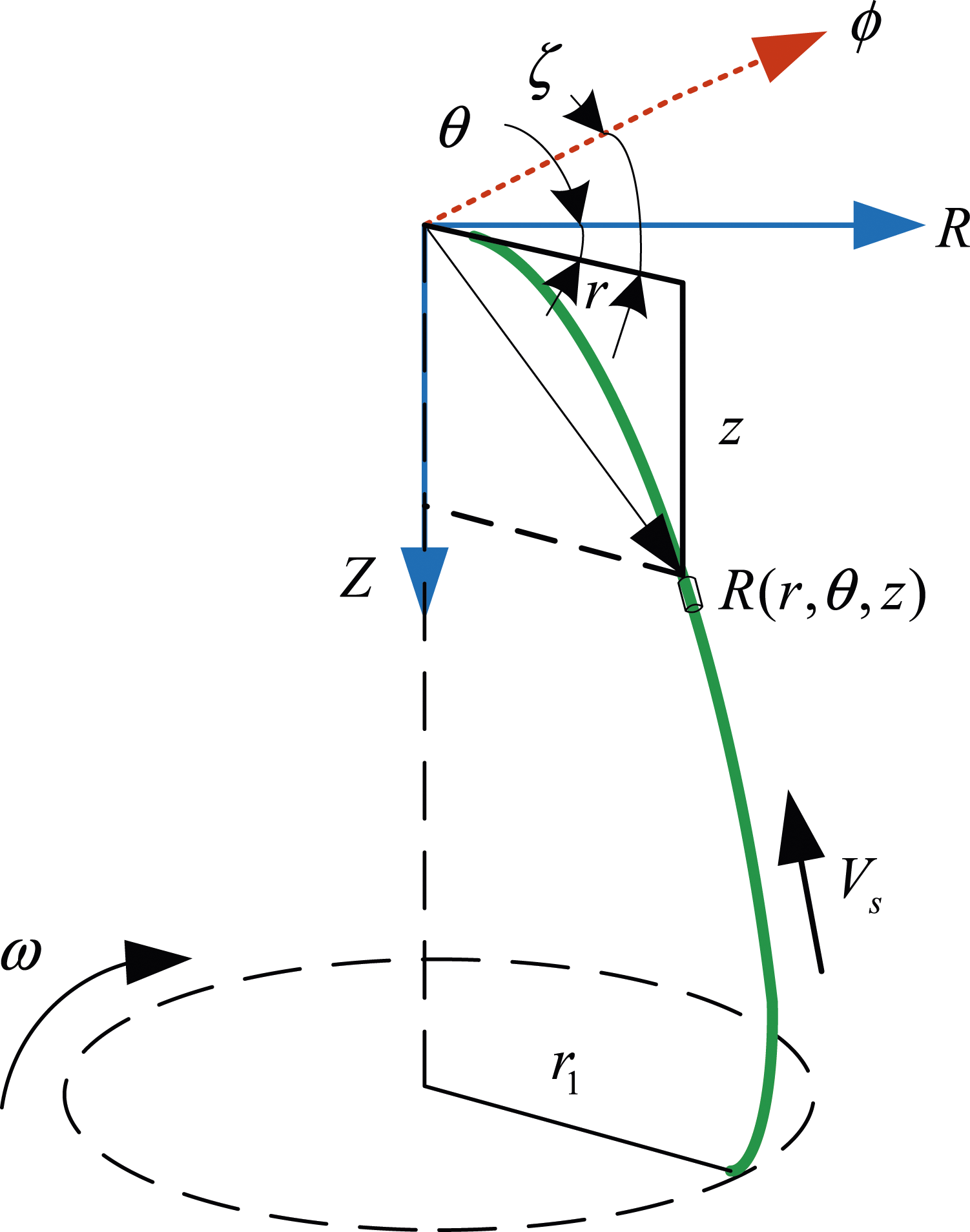

The yarn is in the form of a static spatial curve in a dynamic coordinate system.

The expression of unit tangent vector

The angular speed of spindle rotations can be expressed as follows.


Micro-segment

The motion equations of balloon yarns can be obtained in cylindrical coordinates by combining acceleration and force equations. Equation (6) is expressed in the static coordinate system as

The yarn is flexible without elongation. Only the influence of the normal air resistance on the yarn is considered because normal air resistance is perpendicular to the yarn (see Eq. (8)).

The dot product between equation (7) and

Equation (9) can be expressed as follows by ignoring the gravity of the element.

Equation (10) is substituted into equation (7) to obtain the aerodynamic yarn motion equation (see Equation (11)).
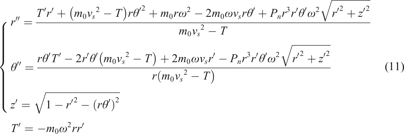
The above derivation formula refers to the derivation formula of the balloon section of yarn in the literature. 31 According to the parameters of the spindle which belongs to the direct cabling machine, the initial value of the mathematical model equation for the balloon motion is determined.
(1) The outer yarn at the top passes through the guide hole at the bottom of the twisting device, whose position determines the radius of the top balloon.

(2) The yarn comes out from the outlet of the storage cylinder and enters section

(3) Figure 4 shows the yarn in the storage cylinder and over-run plate. There will be a wrap angle after the yarn is sent from the outlet of the storage cylinder due to the high-speed rotation of the spindle. The range of wrap angle is Yarn path.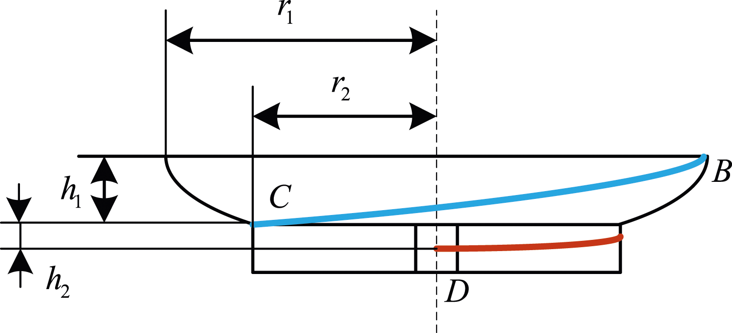

A fan-shaped surface can be obtained by spreading the surface of the over-run plate (see Figure 5). According to the short thread theory, Expansion drawing of the over-run plate.

The length of section

(4) Yarn movement is limited by the size of the spindle can (see Figure 6). According to the above, the constraints of the balloon shape can be obtained. Spindle-can size.

(5) Assuming that the yarn is flexible but not extensible,

Energy Consumption of the Balloon
The twisting mechanism consumes the major energy of the direct cabling machine in the process of twisting the yarn and forming the package. The main energy consumption of the twisting mechanism comes from energy required for spindle rotations in addition to the energy consumption such as the heating and wear of the equipment motor. It includes energy required for spindle idling and spindle rotation, where the latter causes the yarn to form a balloon. Energy consumed by the spindle during twisting is expressed as

If the spindle size and speed and the yarn count unchange, and the wrap angle on the storage cylinder is greater than zero, the storage cylinder will balance the yarn tension according to the changes in the wrap angle. It stabilizes the balloon shape. When the wrap angle is close to zero, there will be no yarn on the storage cylinder, which cannot control the yarn tension. Outer yarn-feeding speed is adjusted to actively control the balloon shape, which solves the failure of the control tension of the storage cylinder. Due to the small friction coefficient on the surface of the storage cylinder, the change in work caused by the reduced friction without yarn winding can be ignored compared to the situation with yarn winding on the storage cylinder.
Yarn subjected to air resistance.

The expression of work done by this segment on air resistance can be obtained as

The expression of work done by the outer yarn on air resistance is as follows.

Work done by the segment
Plane cartesian coordinate system z-r is established. Figure 8 shows the projection of the yarn balloon segment on the plane. Substituted Plane coordinate system of the balloon.

It can be seen that the shape of yarn air coil is mainly affected by yarn density
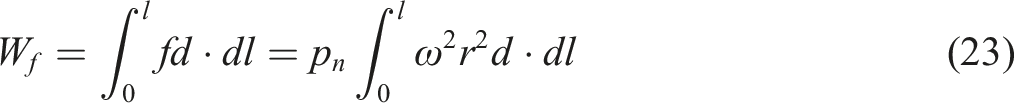
The air resistance of the outer yarn driven by the spindle during high-speed revolution is expressed as

Work done by the yarn in the balloon section on air resistance is calculated as follows.

Simulation
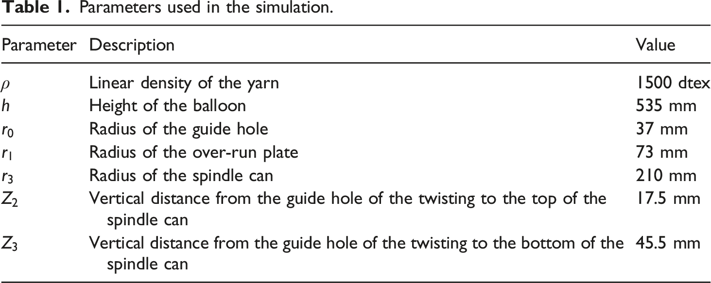
Parameters used in the simulation.
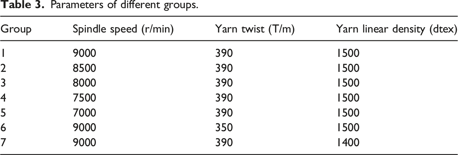
Different parameters of the balloon shape were simulated in MATLAB. The parameters of balloon in different shape are obtained by numerical simulation of equation (11). Parameters are adjusted to maximize the balloon shape. Simulation of the limited balloon. Grouping of the balloon shape.

Parameters of different groups.
Energy consumption was recorded as a benchmark when Relationship between 
Figure 10 shows that the relationship between
The above results show that the variation curve of
Experiments
An experimental platform was established to study the relationship between the balloon shape and energy consumption of the direct cabling machine. TC21 direct cabling machine was the object. TC21 direct cabling machine is a product from Zhejiang Rifa Textile Machinery Co., LTD. It can be used to produce double strand symmetrical tire cord. It is a kind of industrial silk twisting equipment with many advanced technologies. It has the characteristics of large winding, short process and high quality of finished cord. Figure 11 shows the physical picture of the experimental platform, and Table 4 shows the various parameters of the direct cabling machine used in the experiment. Experimental platform. Parameters used in the experiment.

One working unit of the direct cabling machine was used in the experiment to control variables. The stepping motor was used to feed the outer yarn actively, which controlled the feeding speed of the outer yarn by adjusting its speed. The infrared sensor was set at 3/5 of the overall height of the balloon. The balloon radius was the largest according to simulation results. The infrared sensor was used to measure the balloon radius based on the frequency of the yarn movement in its detection area. The speed of the yarn-feeding motor and the balloon radius were controlled near the set value after processing data collected by the control system. The power meter was connected to the working unit of the direct cabling machine to monitor the power change of the working unit used in the experiment.
Figure 12 shows the radius measurement of outer-yarn balloon in the experiment, where the spindle drives the outer yarn to form balloon. One yarn rotation will cut the infrared ray twice caused by the infrared emitter. Infrared-sensor installation. Principle of measuring the balloon radius.


Therefore, the balloon radius of the outer yarn is calculated as follows.
The measured radius of the balloon is compared with the set value of the control system, and the comparison result is used to adjust the speed of the yarn-feeding motor.
When the inlet velocity was not controlled in the experiment, the maximum balloon radius fluctuated between 185 and 190mm. Maximum
Adjust the control parameters until the balloon shape no longer increases to get the maximum balloon shape. Adjust the parameters until the balloon shape is at the edge of the thread breakage to obtain the minimum balloon shape in normal operation. Figure 14 shows the comparison of two balloon shapes. Figure 14(a) and (b) show the maximum and minimum balloon shapes, respectively. Figure 14(c) and (d) show balloon shapes after image processing. Based on the above description, the balloon shape was divided into 11 groups (see Table 5). Balloon in the experiment. Grouping of balloon shapes in the experiment.

Data in the experiment.

Parameters of different groups in the experiment.

The parameters of
The actual power of the direct cabling machine is subtracted from idle power to obtain power consumed by balloon. The power is denoted as a benchmark to calculate K value in the experiment.
Power of the direct cabling machine obtained by the prediction.


Comparison between the simulation and experiment.

Maximum error of each group.
When the spindle speed and the yarn twist and linear density are changed, the energy consumption of the direct cabling machine varies significantly (see Tables 8). The energy consumption of the direct cabling machine increases with the increased spindle speed. Besides, the energy consumption of the direct cabling machine is also in direct proportion to the yarn twist and linear density.
Changing the spindle speed and the yarn twist and linear density has little effect on energy consumption ratio
Errors between actual power and the predicted value in each group of experiments increase first and then decrease with decreased
Conclusions
(1) The work established the mathematical model of the yarn balloon of the direct cabling machine and boundary conditions. Through the analysis of the plane balloon, it is found that the influencing factors of the balloon shape are yarn linear density, yarn twist and spindle speed. Based on the mathematical model, the energy consumption of yarn balloon was analyzed, and a prediction method of energy consumption was proposed based on changes in balloon shapes. Finally, the accuracy of the method was verified by simulations and experiments. (2) The Simulation and experiments showed that the spindle speed and the yarn twist and linear density had little influence on the relation curve between the maximum radius of balloon and the ratio of energy consumption obtained by the energy consumption prediction method for the spindle of the direct cabling machine with the determined structure and size. Therefore, for the same direct cabling machine structure, the energy consumption prediction curve obtained by this method has good applicability. (3) The predicted and experimental values of energy consumption under different yarn linear density, yarn twist and spindle speed were obtained through several groups of simulations and experiments. The result showed that the curves of the
Future work
(1) ptimize the control scheme of balloon of direct cabling machine. Improve the stability of balloon control of direct cabling machine and guarantee the quality of finished product. (2) Optimize the algorithm of control scheme and improve the accuracy of energy consumption prediction method. (3) Applying it in the actual production process, and optimize the balloon control strategy of direct cabling machine. (4) The amount of experimental data was increased to further verify the accuracy of the method through more experimental data. (5) Further research is carried out to explore the resource allocation problem of the production workshop of direct cabling machine based on the research results, and optimize the resource allocation in the process of cord processing.
Footnotes
Declaration of conflicting interests
The author(s) declared no potential conflicts of interest with respect to the research, authorship, and/or publication of this article.
Funding
The author(s) disclosed receipt of the following financial support for the research, authorship, and/or publication of this article: National Natural Science Foundation of China; 11872337, 91841303