
Abstract
The inherent complexity of textile preforms and a high degree of consistency in dry fabrics and yarns present a number of modeling challenges, including uncertainty in geometrical characteristics under external loads, non-elastic deformations of fibrous media, and multiple deformation modes at the fiber and yarn scales. The prediction of the compaction reaction for different preforms is still possible thanks to the direct measurements of yarn compaction. The data are checked against compression stress-thickness curves that were produced by compacting yarns and preforms. The yarn and fabric compaction model given in this article demonstrates the final characteristics of woven preforms. The yarn compaction curve exhibits asymptotic hardening with a restricted compaction state attained at high compression stress and as the limit deformations are being approached. The yarn count, yarn fiber volume ratio, and the spinning method all affected the compression modulus. The transverse compression behaviour of yarns and fabrics was studied both analytically and experimentally. Mechanisms of fabric compressibility have been found to be reliant on both fabric and yarn specifications of warp and weft Young’s modulus. Investigations were made into the fabric’s fiber volume fraction under compression stress. When producing composite with low fiber volume fraction preforms, it may be more efficient to use more compression, according to research on the link between compressive stress and fabric volume fraction. The relationship between the compressive stress and fabric volume fraction was investigated, as well as the value of maximum compression stress.
Keywords
Introduction
Fabrics are subjected to several types of stresses during their manufacturing processes and service life. Among these stresses, transverse compression is a critical factor affecting the mechanical behavior and performance of cotton yarns and fabrics. Transverse compression refers to the pressure applied perpendicular to the length direction of yarns or fabrics.
Textile polymer composite materials are crucial components in aerospace and automobile building structures due to their lightweight, corrosion-resistance, and damage tolerance. They can be produced using a variety of techniques, including open-contact molding, resin infusion technique, compression molding, and injection molding. 1 In the majority of the aforementioned techniques, pressure is applied to the cloth to enable the infusion of the matrix polymer. Pressure is necessary in the case of multi-laminate composites in order to maintain high interfacial shear pressures on the fabric laminates and prevent the development of flaws like micro-voids between fibers or yarns. Such gaps will have an impact on the composite’s strength and delamination.
Such voids have an impact on the strength of the composite and the development of delamination, which may take place in one or more areas of the composite.1,2,3,4,5,6 Fibrous preforms that are being used to create composite materials are compressed to the intended composite dimension. When yarn is compressed transversely, the yarn distribution and fiber volume fraction change, which affects the resin impregnation velocity when making composites and the end mechanical properties. 7 The pressure required to push the resin through the matrix is created when the fabric is saturated, and the resin has completely filled all of the pores. It should be sufficient to create a resin flow through the yarns and between the yarns, leading to fabric compaction. The yarn, fabric porosity, and resin viscosity—especially for those produced under pressure—are the key factors that control the flow of fiber reinforcement. 8 The resin must be forced through intra- or inter-pores in the yarns or textiles under high pressure. This pressure will be influenced by the fiber packing density distribution in the yarn cross-section, yarn count, yarn twist factor, type of spinning system, and fabric specifications, including cover factor, fabric design, number of wefts and warp/cm, yarns crimp, and fabric areal density. (GSM).
Yarn flattening is essential, for example, for the estimation of fabric porosity, air permeability, and mechanical characteristics in terms of ultimate and user range loading. 9 Because of the different nesting behaviors of fiber and yarn structures, the compressibility of these various fabric structures varied for several types of fibers. The preforms' thickness and fiber volume fraction change as a consequence of the degree of textile fabric compression. The compaction of the fabrics also affects how the resin flows and the mechanical characteristics of the finished product, making it a crucial production process parameter. 10 Investigating the thickness and microstructural alterations of fabric preforms under loading during compaction while composites are being processed is therefore essential. The non-uniform matrix structure is one of the primary flaws in the final product. 11 It was discovered that pressure applied during the matrix’s curing has a substantial impact on the chemical shrinkage. This leads to the inference that, for the specified values of yarn fiber volume percentage and pressure applied, the volume of chemical shrinkage will be lower for the stiffer reinforcements. 12
A principal factor in determining a fabric’s appearance is the shape of the yarn cross-section. It was claimed that a yarn’s cross-section could be viewed as an irregular hexagon as early as. 13 The irregularity is brought on by an uneven transverse distribution of the fibers due to the tension distribution brought on by interactions among, among others, the fiber property, yarn property, and spinning parameters. In previous studies, the majority of scholars assumed that the yarn in bobbins has a circular cross-sectional geometry to facilitate calculations. Ring and rotor-spun fibers have an ellipse flattening ratio and are closer to ellipses.14,15
The yarn used in weaving processes is typically stretched, curved, and flattened; the majority of methods categorized the yarn’s cross-sectional shape as circular, and elliptical, and assumed that it had a constant cross-section. 16
This led to variations in the cross-sectional shape of the yarn depending on the types of fabrics and yarns used in the design.
The shape and amount of the gaps between the warps and wefts, which make up a plain or twill woven cloth, determine how permeable it is to air. Due to the fabric’s low stiffness, it is easy to compress it when subjected to through-thickness air pressure, which leads to a tighter yarn crossing and a flatter yarn path. A flatter, flatter-oval, or flatter-elliptical textile cross-section then develops.17,18,19,20,21,22,23 Later, when considering models like the cylinder, hydraulic diameter, parabolic curve, etc., researchers put a lot of stress on the gap geometry.24,25,26,27 These models demonstrate that the gap permeability is typically substantially greater than the fiber volume fraction, which includes the fabric porosity value. The transverse compression behavior of cotton yarns and fabrics can be studied using experimental and numerical methods. This article provides an analysis of the transverse compressive behavior of cotton yarns and fabrics.
The compaction behavior of different yarn structures as well as the fabric produced from them has both been studied in this study to investigate how these fabrics' thicknesses change if tested under varying pressures, simulating various composite manufacturing processes.
Material and methods
Measuring the compactness of the yarn and fabric
Measurement of yarn or fabric thickness
In order to determine how these fabrics' thicknesses, change when tested under various pressures, mimicking various composite manufacturing processes. The yarn and fabric thickness was measured using the thickness measurement apparatus shown in Figure 1. Apparatus for measuring the yarn and fabric compactness.
A steel block with a width of 25.4 mm had been wrapped in yarn, which was wound in 30 coils. Under the presser foot of the apparatus, a glass plate was placed on top of the strands. When the presser foot is lowered onto the substance being measured, pressure is applied to the yarns, and the dial gauge displays the yarn thickness.
For 10 pairs of yarn, the thickness of the yarn was tested. Each yarn set or cloth sample (25.4 × 25.4 mm) had been subjected to applied loads of 100, 500, 1000, 1500, and 2000 cN under a glass plate at the instrument’s base. once releasing the weighted pressure foot, pressure is applied for at least 5–6 s.
Measurement of yarn width
Most spun yarn has an elliptical cross-section instead of a circular one, particularly when the yarn is compressed.
1
The intended setup depicted in Figure 2 was used to measure the width of the yarn under the applied pressure. The yarn bobbins were positioned in yarn holders and led through the measuring region between two parallel pieces of glass. The yarn has been deformed as a consequence of loads placed on the upper glass plate. The yarn has been deformed as a consequence of loads placed on the upper glass plate. Figure 2 depicts photos taken using a camera attached to a laptop of the yarn deformation along its breadth. 10 sets of yarns were used to determine the yarn width; the applied loads were 100, 500, 1000, 1500, and 2000 g for each yarn. 10 separate locations along the length that was measured were used to gauge each yarn’s width. Measuring set-up for yarn width.
The yarn packing density
Cotton ring spun yarns with different counts are prepared according to the IS 46-108-01/01 standard from different Egyptian kinds of cotton (Giza 90, Giza 88, Giza 87, and Giza 86) for packing density investigation. The instrument used in this study was developed in the laboratory of the Faculty of Textiles at the Technical University of Liberec, CZ. 28
Yarn's mechanical properties
Yarn specifications and mechanical properties.

Coefficient of variation %.
Fabric thickness measurement
Fabric specifications
The fabric sample specifications.

Standard deviation.
Fabric strength
Mechanical properties of fabric samples.

Standard deviation.
Results and discussions
Yarn compression model
A textile polymer composite material is a combination of two or more component materials that work together to create composite properties. The matrix is one of these components, and reinforcement in the form of fibers, yarns, fabric, or particulates is another important portion that helps the matrix’s properties. Understanding the yarn structure is crucial because it enables evaluation of the yarn limitations and their change during additional fabric processing in the finished composite material. The geometry of the fibers and their spread along the yarn’s length and cross-section determine the structure of the yarn. Either an oval or an elliptical cross-section makes up the thread.28,29 Due to a shift in compression to a flatter profile, the yarn cross-section is circular. 9 Depending on the technique used to create the yarn, such as the spinning system used (ring spinning, compact spinning, open-end spinning, or air vortex, 30 ), it was discovered that the packing density of the yarn varied.
Figure 3(a)–(d) demonstrate the yarn cross-section of various count 20 tex ring-spun yarns spun from various Egyptian kinds of cotton. (Giza 90, Giza 88, Giza 87, and Giza 86). (a), (b), (c), (d), (e). Packing of the fibers in the yarn cross-section.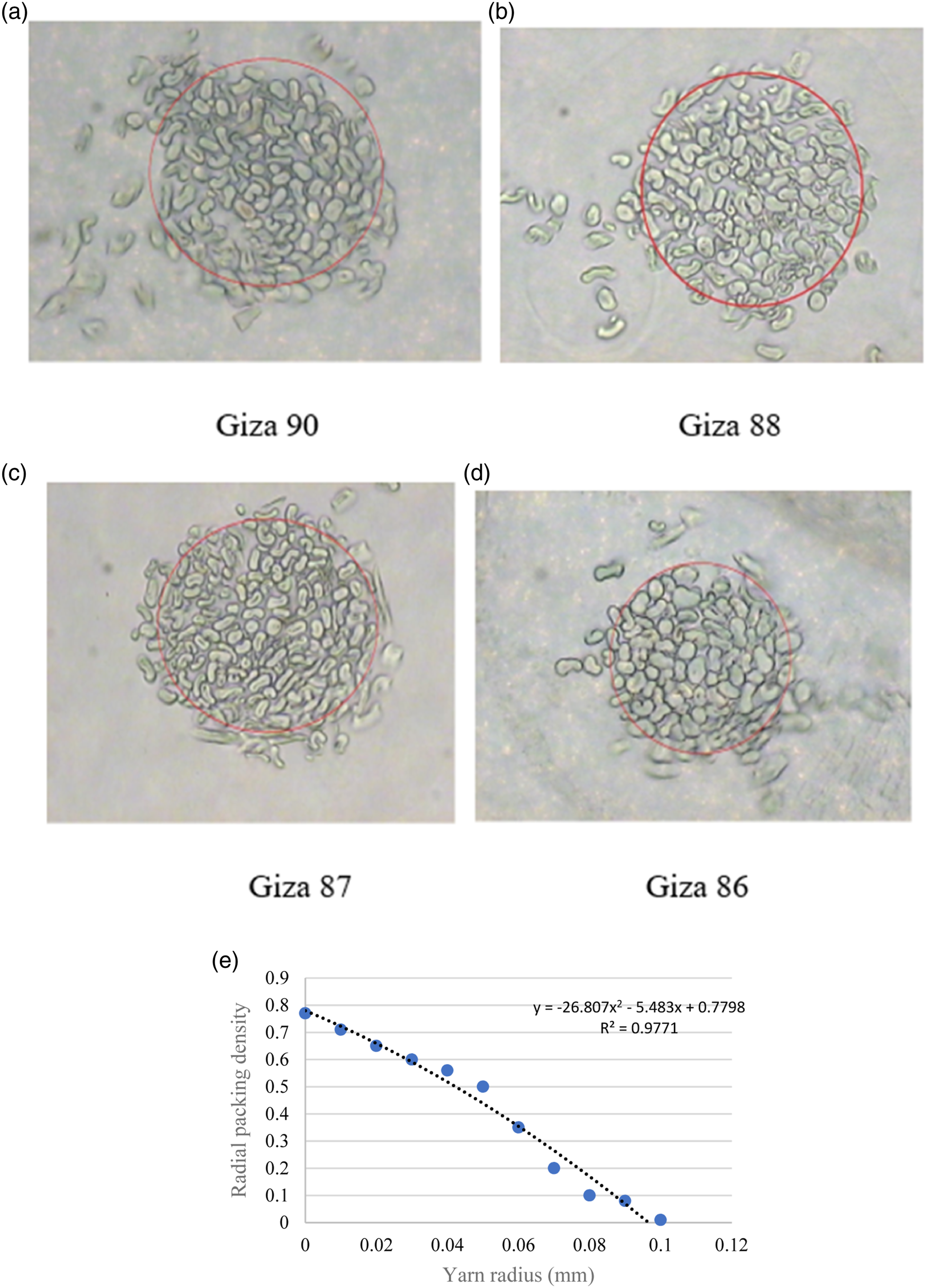
The configuration of the fibers within the yarn cross-sections has a significant impact on how the yarn deforms in response to compression pressures. The radial packing density, which depicts the variation in its value across the skein radius, is shown in Figure 3(e). In the middle, the radial packing density is at its highest value of 0.77. The average packing density will be 0.51 and this means that the yarn has open areas in its cross-section that enable the fiber to move from its compressed positions.
Typically, when a force is applied to a yarn, the fibers are forced to shift in relation to one another based on where they are located in the yarn cross-section. Depending on how the fibers are arranged, they travel differently within the yarn.
31
The chance of different fibers being relocated inside the yarn cross-section depends on the twist, fiber-to-fiber friction, and size of the gap between them. While the fibers are organized in close packing in a hexagonal design, they are in open packing in a series of concentric circles. In both configurations, the fibers on the various skein cross-sectional areas are unstable, and a compression force will typically press the fibers inside the yarn’s cross-section, as shown in Figure 4. When there is a relative displacement between the fibers due to compression pressures, static friction becomes dynamic friction as the compression force increases. The other contracted fibers will support the pressing force F acting on the fibers, and the existence of gaps between the fibers will cause the fiber to move inward until it rests on other fibers to withstand the pressing force. Up until every fiber in the yarn cross-section is rigidly supported by every other fiber, the procedure will be repeated. The extension yarn cross-section axis (2a) will increase, and the axis will decrease due to the movement of the fibers on the yarn surface that primarily move in the initial yarn body reduces the axis (2b). Forces acting on the fibers apply a compression force F in the presence of a gap between fibers.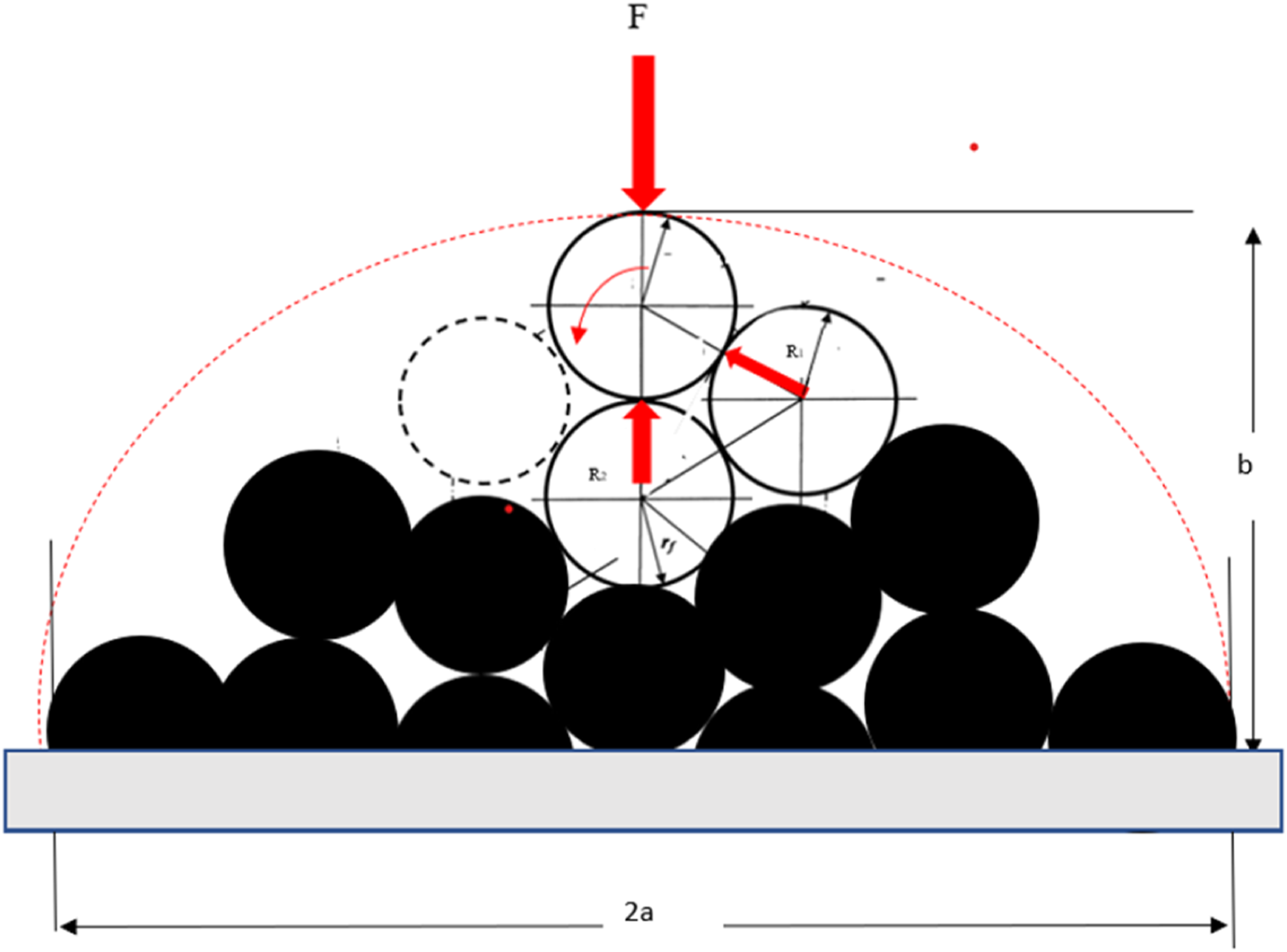
Figure 5 shows how the fibers will be further compressed as the compression force increases. During its compression, the fibers' cross-section size may also alter. The yarns' radial packing density will first rise during the first stage of the compression process, then the ratio (a/b) will rise, and the fabric’s packing density will rise as the yarns are moved into various positions. Yarn deformation under an increasing compression force.
The deformation of the yarn under compression
Figure 6 shows the cross-section model of individual yarn, with the major axis of 2a and the minor axis of 2b. Other parameters are fiber porosity Vf, the yarn cross-section area (πab), yarn cross-section perimeter π (a+b), and yarn compression factor (flattening coefficient) e = a/b. Assuming the spaces between the fiber cross-section are the lowest that is fibers are tightly packed in such case the compression stress will deform the yarn cross-section, so its perimeter increases while the cross-section area is kept almost constant.
16
The value minor axis 2b under compression stress is shown in Figure 6, which indicates that the finer the yarn, the compression deformation rate decreases. the pressure-thickness curve shows that the greatest reduction in thickness in response to the increase in pressure was detected in the range of up to 6 N/cm2. The finer the yarn the reduction of its thickness under the compression stress is lower than in the case of coarse count yarn, this may be due to the fact the packing density of fine count is less than that of coarse yarn consequently the yarn cross-section will be deformed at compression stress and reaches the final compact cross-section under lower compression stress than course yarns.
32
a,b.c,d,e. Yarn-measured b value versus compression stress for, Ring spinning, compact spinning, and open-end spinning yarns. (a) Deformation of yarn under compression stress for ring-spun yarns. (b) Compression stress-compression strain curve for different ring-spun yarns. (c) Yarn thickness versus compression stress. (d) Compression stress-compression strain curve for Ring-spun(RS) Compact (Com), and Open-End (OE). (e) Ratio (a/b) of Ring-spun (RS) Compact (Com), and Open-End (OE).
Figure 6(a) displays the thickness values for the various ring-spun yarns under compression stress. With increased stress, there was less of a decrease in yarn thickness across all yarn counts. However, the decrease under compression stress will be less the finer the yarn. Samples four and six showed the greatest decrease in yarn thickness, 26% and 24%, respectively. The thickness of the other two yarns decreased by about 19 and 16%, respectively. This may be due to the fact that greater yarn diameter and less dense packing result in greater compression strain when under compression tension. 33 Figure 6(b) depicts the compression stress-compression strain curve for different ring-spun yarn types. The impact of various spinning methods on the compactness of yarn produced by ring spinning, compact spinning, and open-end spinning is depicted in Figure 6(c). Due to their higher packing density than ring-spun or open-end spun yarns, 28 compact spinning yarns have packing densities between 0.55 and 0.7, compared to 0.5-0.6 and 0.42-0.55 for combed and carded cotton ring spun yarns and 0.4-0.46 for open-end spun yarns, respectively.32,34
As a result, it will be discovered that the compression strain of the various yarns under various values of compression stress will be greatest for open-end yarns and lowest for compact spun yarn, Figure 7(d). By lowering the value of (b) and raising the value of (c), the flatness of the elliptical shape of the yarn cross-section will change under the compression stress. (a). The type of spinning system used was discovered to have an impact on the value of (a/b) for yarn cross sections. Figure 6(e) illustrates the relationship between (a/b) versus compression stress for a variety of yarns. It was found that OE yarns are less stiff than other yarn structures, such as ring-spun or compact-spun yarns, so the value of compression strain is higher. According to the analysis of the data, each variety of yarn was found to have a constant value for the peripheral of the yarn cross-section when subjected to a range of compression stress levels (see Figure 7). Compared to the ring-spun yarn of the same count, the compact spun yarn has smaller values for the change in the peripheral of the yarn cross-section. Flattening of yarn cross-section versus compression stress. (a) Flattening of cross-section versus compression stress of ring spun yarn. (b) Flattening of a cross-section of OE, RS, and COM yarns versus compression stress.
Yarn compression modulus
The behavior of yarns under compression stress can be characterized by the compression modulus (compression stress/compression strain). It has been found that the yarn count and spinning method affect the compression modulus of the yarns. Its value is greatest for Compact spun yarns, as shown in Figure 8. It was discovered that the value of the compression modulus dropped as the yarn’s fineness increased. This might be a result of the finest yarn’s greater fiber packing density compared to coarse yarn. The thicker yarns end up being less compact for yarns with various yarn counts.
34
As a result, the fibers will be tightly packed in the yarn cross-section, leaving less room for the fibers to shift from their initial positions. Compression modulus versus the yarn count.
The deformation of the fabric under compression load
The analysis in the paragraph above revealed that the yarn will flatten when subjected to a compression force; consequently, the yarn and weave specifications will affect the ratio of the value a/b. Along the weaving unit, the yarn will deform variably. The value of a/b is at its highest in the center of two intersection spots and starts to decline at the center of the yarn length l.
35
When woven fabrics are compressed, the normal forces between the yarn networks cause the yarn to flatten out as a consequence of the compression process. The length of the yarns will be compressed once the values of bwarp and bweft hit their minimum values, after which the warp and weft of the yarn will be compressed at the cross-sections. As a result, there were variations in the cross-sectional shape of the yarn along its route, providing a more accurate representation of the appearance of the yarn-woven fabric. Numerous scholars have studied the fabric’s geometry in depth.11,35,36,37,38 Figure 9 displays the plain weave’s basic block. Plain weave geometry.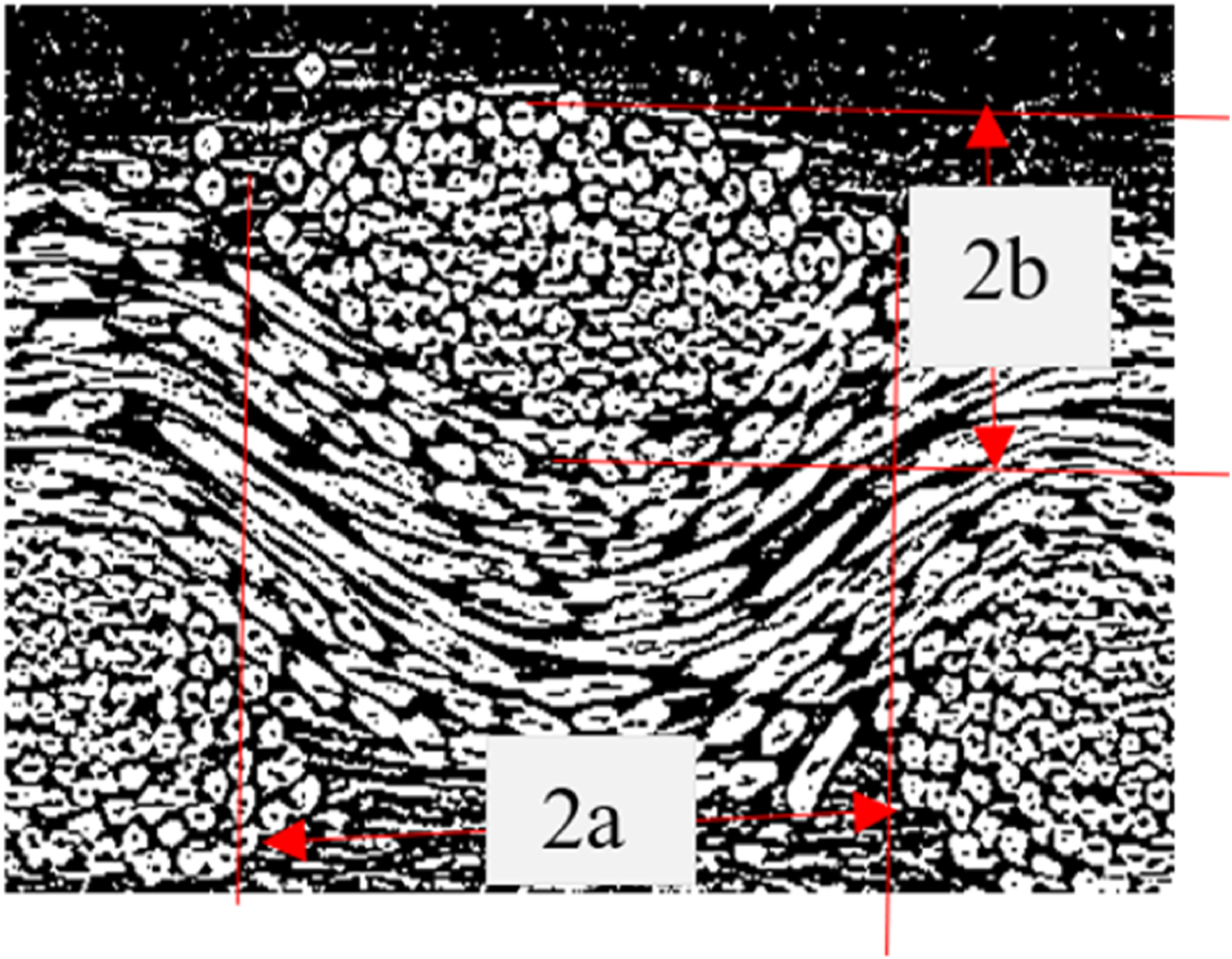
The experimental measurement revealed that the yarn cross-section is not circular but rather tends to be elliptical, with 2b denoting the minor ellipse and 2a the major ellipse, as shown in Figure 9.
Fabric under compressive stress
Geometrical hypothesis
The structure of the fabric as well as the yarn’s deformation under compression stress both have an impact on how the fabric behaves. Figure 10 shows the unit fabric at its starting state while being subjected to a force Pi; as the pressure increases, the yarns begin to deform. A simple geometrical model for pressing a plain weave.
The compression behavior of textile yarn is illustrated in Figure 11; when a fabric is compressed, the yarn will deform either in the warp or weft orientations. Fabric deformation under compression load.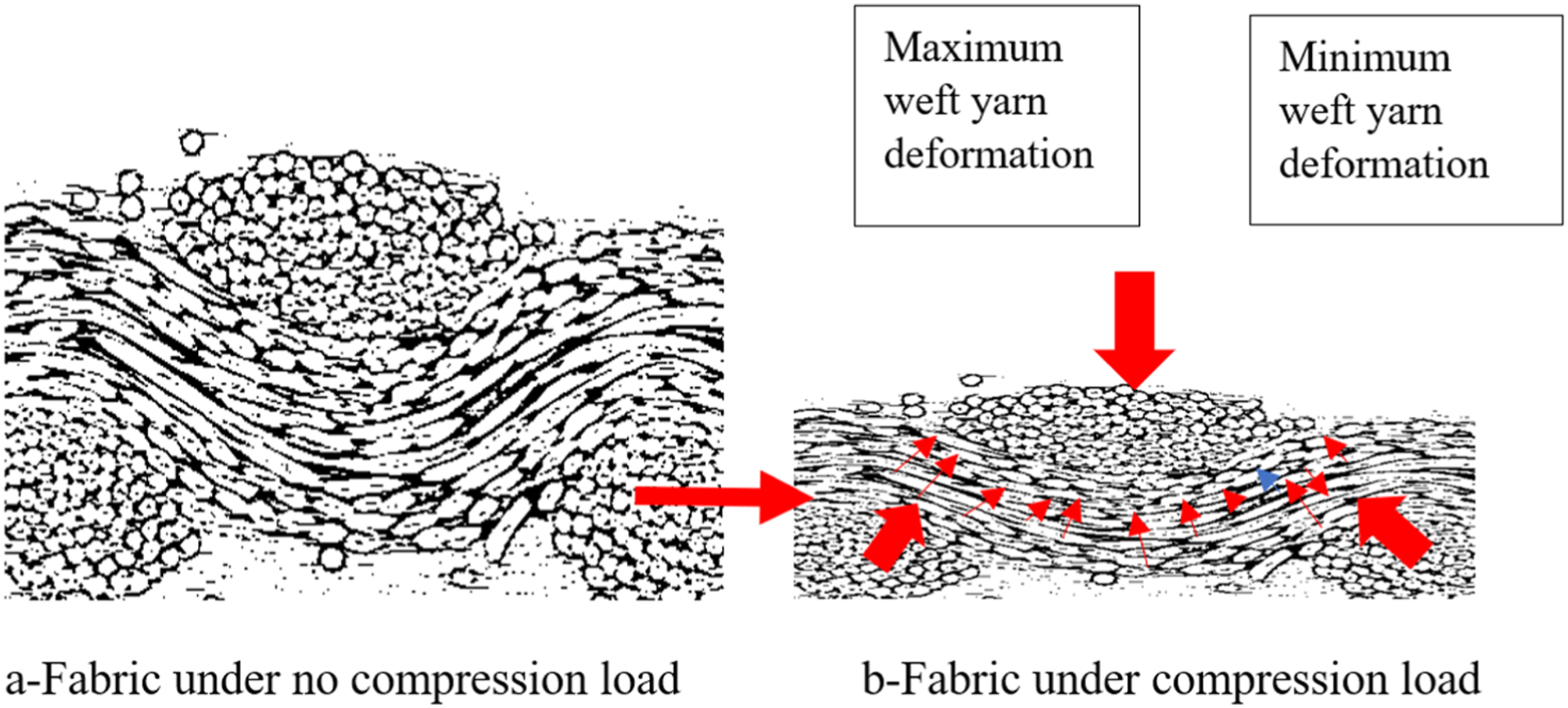
The compression stress will reduce the elliptical radius (b) while the other axis will increase consequently, the value a/b will be increased too. This deformation continually happens as the value of 2a1 < p2 – 2a2 or 2a2< p1 – 2a1. i.e., fabric reach jamming.
Where: 2b1 = minor axis of the ellipse, 2a1 = major axis of the ellipse of warp yarns, 2b2 = minor axis of the ellipse, 2a2 = major axis of the ellipse of weft yarns. p1 = 1/n1 and p2 = 1/n2, n1 = number of weft yarn per cm, n2 = number of warp yarns per cm.
The flattening factor is defined as e = (b/a) 0.5
Di = 2b1 (i) + 2b2 (i)
It is noted that the minimum yarn flattened ratio occurs at the intersection point, which means the yarn is heavily flattened. However, it is the maximum in the middle of two intersection points.
16
The further increase of pressure will change the yarn cross-section shape from Ellipsoidal to Racetrack. Figure 12 shows the extreme values of the cross-section diameters in the case of plain and twill weave one-half. The model of maximum compression of plain and 2/1 twill fabrics.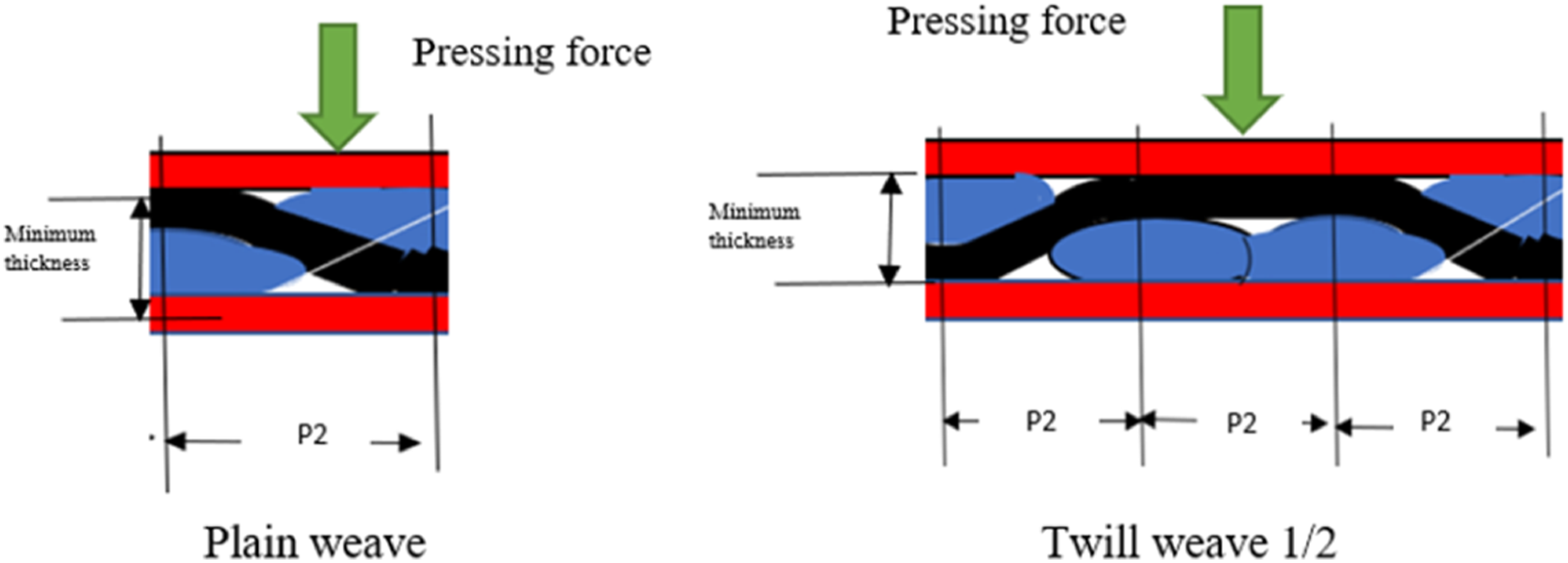
When the warp and weft yarns reach their minimum value of bmin and the value of (a) reaches their maximum value of amax, the fabric will have reached its minimum thickness of tmin, presuming the p2 and p1 remain unchanged during the fabric pressing. The fabric typically becomes completely packed as shown in Figure 12 for total jamming of the fabric under the compression force. In this scenario, both the fabric packing density and the packing density of the yarns will be at their highest theoretical values. (packing density is the fiber volume fraction of the yarns or the fabrics).
Assume woven fabric shapes that include circular yarn cross-section, full yarn flexibility, incompressible yarns, and arc-line-arc yarn path in order to determine the value of plain weave fabric packing density.39,40,41 Figure 12 demonstrates how the plain weave can pack fibers more densely than other fabric types, like twill structures. The fiber volume fraction,
42
which as previously stated is a function of the compression stress applied to the composite during manufacturing, is one of the crucial factors that should be considered when selecting natural fiber as reinforcement in polymer composites.
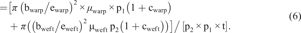
The application of compression stress on the surface of the fabric will lead to the deformation of the warp and weft yarns the volume of the fabric unit will reduce as a function of the applied stress. l1 = p1(1+ cwarp), and μwarp is warp yarn packing density. Μweft is warp yarn packing density. B = minor axis of the ellipse, a = major axis of the ellipse l1, l2 is the modular lengths of the warp and weft yarns, respectively, in one repeat, cwarp, cweft is the contraction % of the warp and weft yarns, respectively, in one repeat, The cross-section flatness e= (b/a)0.5 a = b/e2 Then


The fabric packing density defines the fiber fraction for fabric polymer composite materials which determines the mechanical properties. Consequently, the pressure applied to the fabric during the manufacturing of the composite should satisfy the fabric packing density required. The higher the fabric packing density value, the higher the matrix’s weight that can penetrate the yarn and between the yarns. Consequently, fiber volume fraction typically results in the mechanical properties of the composites.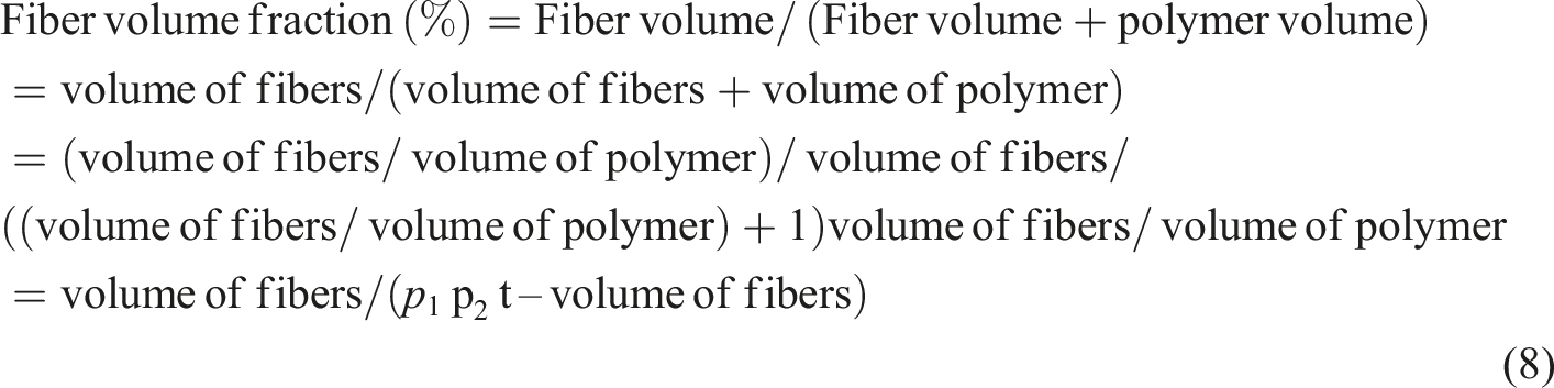
Assume
A = 1/(2p1 p2 (bwarp + bweft) – 1)
Then

From equation (9), it is clear that the value of the Fiber volume fraction (%) depends on the behavior of the deformation of the yarn under compression stress.
Under the compression, the value of A will be varied depending on the value of the pressure (p) equation (8) can be rewritten as
A(p) is the value of A when applying pressure p on the fabric surface.
The fabric compactness
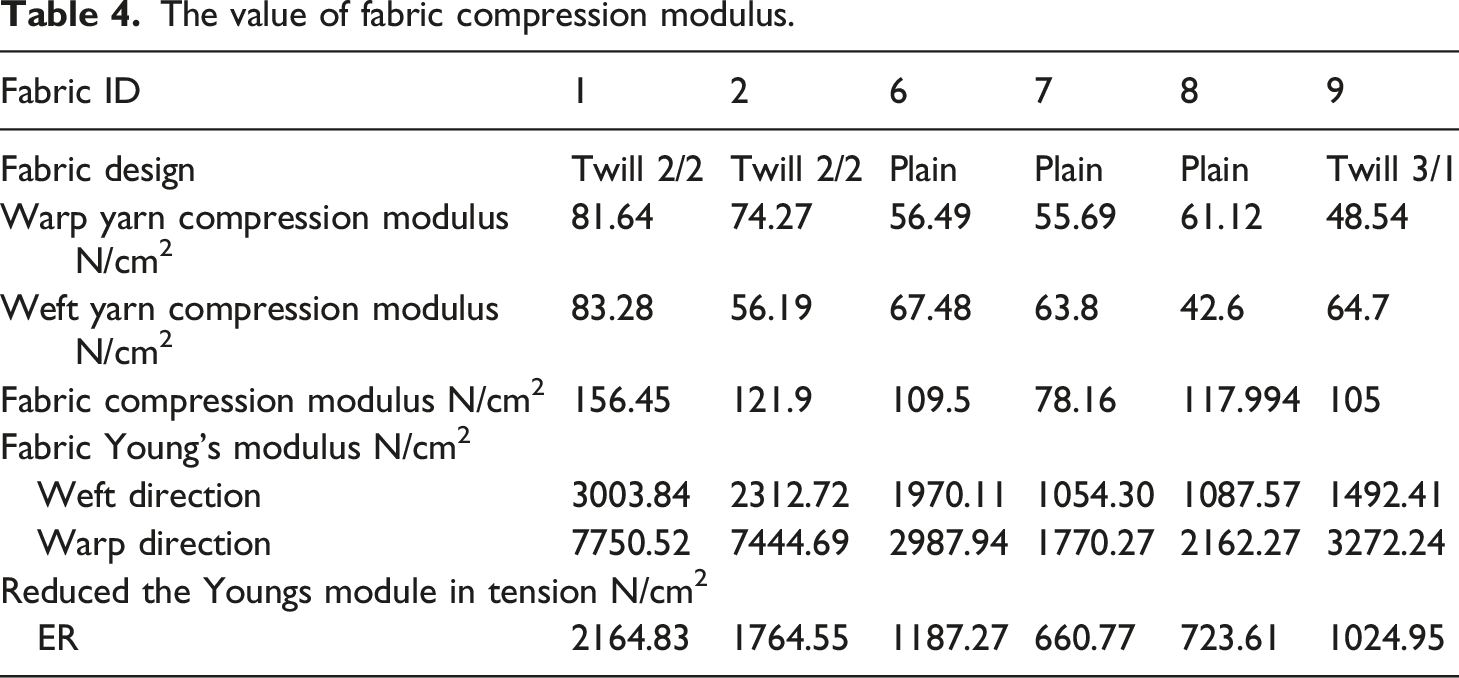
The value of fabric compression modulus.
The measured fabric thickness versus compress stress for different samples are shown in Figure 13. The fabric thickness versus the compression stress.
The conclusion drawn from Figure 13: As compression stress rises, fabrics' resistance to compression increases quickly. Additionally, the slope of the curve becomes steady as pressure rises above a certain point. Figure 14 shows the relationship between the compression strain and stress for various textiles with various compression moduli. Compression stress versus compression strain.
The fabric compression modulus
If (F) is the total compressive force applied, (A) is the fabric area, (t) is the average fabric thickness, and (t) is the measured transverse fabric deformation, then these variables are given in the example. The compression modulus will be equal to {(F/A)/(δt/t)} (44) when the compression tension (F/A) and compression strain (δt/t) is present. The fabric’s compression modulus is determined by the fabric’s specifications as well as how the yarn responds to compression tension. It was observed that, as shown in Figure 15, the fabric compression modulus is inversely proportionate to the fabric areal density. The fabric’s compression modulus increases with fabric areal density. The fabric compression stress versus the fabric areal density.
Stress is complicated in the case of the deformation of the warp and weft yarns under compression because of the structure of both yarns. However, suppose that the warp and weft at the interlacement adhered to the model of two cylinders in line contact in order to show the model. As the compression stress rises, the contact line at the point where two cylinders meet grows into a tetrahedral shape.
43
The value of the width of the contact surface will be proportional to the root of (1/ER). ER is the reduced Youngs module in tension N/cm2. E1 is the Youngs module of warp yarn N/cm2. E2 is the Youngs module of weft yarn N/cm2.
Consequently, the compression modulus is expected to be proportional to (ER). Figure 16 shows the relation between the compression modulus and the reduced modulus of elasticity in tension. Fabric compression modulus versus reduced Youngs module in tension (ER).
From the analysis of results, it was revealed that the increase in the fabric areal density through the higher number of the warp and weft per cm leads to the expansion of the compression modulus, Figure 16. In the meantime, the use of yarns with high Young’s modulus leads to an analogous effect, hence the values of fabric-reduced Young’s module in tension (ER) will be higher.
The fibers volume fraction of the fabric under compression
The following equation, presuming the yarns have a circular cross-section, can easily be used to calculate the fiber volume fraction of the weaving unit, which is equal to the ratio of the volume of the fibers to the volume of the unit weave.
28
dwarp(i) is the average major axis of the ellipse of the warp yarns at the side of the unit cell, mm. dwarp(i) = 2awarp (i) dweft (j) is the average major axis of the ellipse of the weft yarns at the side of the unit cell, mm. dweft (i) = 2aweft (i) n1 is the number of warp yarns per cm. n2 is the number of weft yarns per cm. is the yarns fiber volume fraction. Φ(i) is the yarn fiber volume fraction. 2awarp (i) = Major axis of the ellipse of the warp yarn(i). 2aweft (i) = Major axis of the ellipse of the weft yarn(i).
Assume the weft and warp have the same specifications then
During the compression of the fabric, both warp and weft yarns will compress, as well as the yarn fiber packing density of the yarns increased, consequently, the fabric volume fraction will be changed. Applying equation (13), the fabric fiber packing density value at different compression stress can be calculated.
Figure 17 demonstrates the relationship between the fiber volume fraction and the compression stress applied for the fabric samples. The compression stress versus the calculated fabric fiber volume fraction.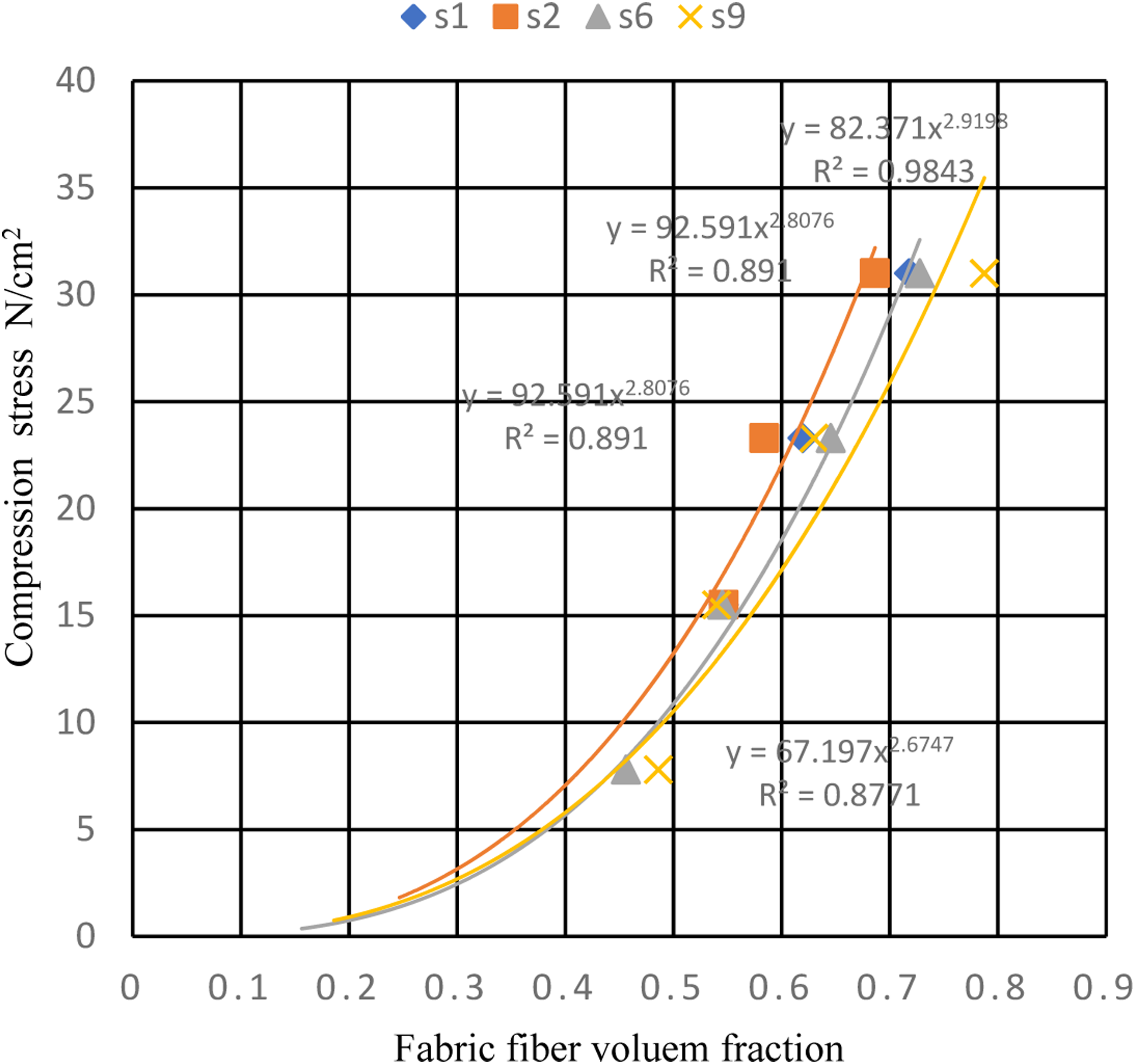
The fabric's maximum compression stress
Experimental studies have shown that the transverse compressive behavior of cotton yarns and fabrics depends on several factors, including the yarn/fabric structure, and compression stress. For instance, the transverse compressive modulus of cotton yarns increases with the increase in yarn count. Similarly, fabric construction affects the transverse compression behavior of cotton fabrics, such as weave patterns and yarn density.
Maximum compression stress.

Fabric maximum volume fraction
Two packing arrangements—open packing and hexagonal close packing—were taken into consideration, with the assumption that the fiber structure comprises yarns with circular cross sections. For the latter, the maximum value is 0.785, while for the former it will be 0.887.
30
When the fabric is under pressure, its thickness will decrease, and the yarn’s maximal fiber volume fraction will then be reached. The cloth framework will become obstructed. The highest fiber volume fraction of the fabric will be.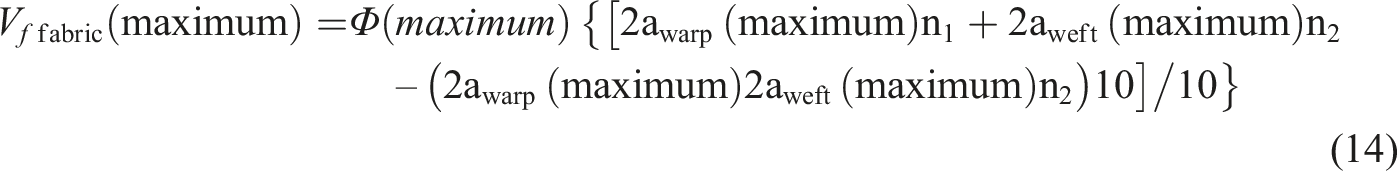
Maximum fabric fiber volume fraction.


Conclusion
The selection and design of fabric mechanical properties can be properly made with the aid of knowledge of yarn properties and their compactness under pressure, resulting in appropriate values for the fiber volume percentage of preforms compressed during the production of composites. Geometrical factors affect the weave of the fabric. The fabric mathematical models can be used to describe some parameters, while experimental measurements are used for the other parameters. The following is implied by the theoretical and experimental evidence. 1. During the first stage of the compression process, the radial packing density of the yarns will first rise, followed by an increase in the ratio (a/b), and the fabric packing density will rise as the location of the yarns is changed. 2. As pressure is applied, the rate of compression deformation reduces the finer the yarn. 3. It was found that the yarn count and the method of the spinning system affect the compression modulus of the yarns. The greatest ranking is held by compact spun yarns, then ring spun, and finally open end. 4. The fabric’s deformation under compression load depends on the fabric’s decreased Young’s modulus in tension ER and the constitution yarn’s compression modulus. 5. Because of the fabric’s specifications and design, the highest fabric fiber volume fraction under compression stress is lower than that of the warp and weft yarns.
In conclusion, the transverse compressive behavior of cotton yarns and fabrics is a key factor that affects their mechanical behavior and performance. Experimental and theoretical studies have provided valuable insights into the transverse compressive behavior of cotton fabrics.
Footnotes
Declaration of conflicting interests
The author(s) declared no potential conflicts of interest with respect to the research, authorship, and/or publication of this article.
Funding
The author(s) received no financial support for the research, authorship, and/or publication of this article.