
Abstract
Increasing demand for high-performance applications of composite materials requires an integral forming process for complex components. As a composite reinforcement, 3D (three-dimensional) woven fabric has advantages in producing near-net-shaped preforms. However, previous studies focused on plates with uniform thickness, which are often variable thicknesses or special-shaped parts in practical applications. Some structures are prepared by stitching and then formed in the mold, but this increases the fiber damage. This study proposes a fabric design method based on yarn movement. By controlling the movement direction and distance of each yarn, the warp path in the fabric can be designed, which cause the change of fabric structure and achieve the integrated forming of special-shaped preforms. Based on this method, a software package for the preforms design and simulation is developed, which can be used for various woven and 3D textiles to illustrate its versatility.
Introduction
3D woven composite materials have been widely used in the aerospace, defense, and military industries because they overcome the delamination failure of 2D laminates and offer high fracture toughness, impact damage tolerance, and excellent fatigue resistance.1–3 Previous experimental studies have focused on plates with uniform thickness, but in practical applications, 3D woven composites often have variable thicknesses or special-shaped structures, such as turbine blades and antenna housings. 4 Special-shaped, integrated composite structure members are required to bear different loads at different parts, such as the integrated rudder where the surface bears a bending load, and the shaft bears a torsional load. 5 So the fiber preforms to be used as reinforcement needs to be designed with two different structural response behavior.
The traditional 3D weaving process can only produce a single structural component because the yarn arrangement does not change during the weaving process. For the special-shaped 3D woven preform, two manufacturing methods have been selected. One is to weave the fabric with special shapes directly from special equipment and weaving technology,6–8 producing fabric preforms with variable thickness, 9 tubular shape, 10 and node structure. 11 In this case, the production equipment has some limitations: it can only weave a single structure at one time, and the size of the preform is restricted to certain dimensions. The other is to manufacture near-net-shape preform by cutting and stitching the single structural part and then forming in the mold during the post-processing process.12,13 It is widely known that the cross-section shape, orientation, and interlacing state of yarn in the composite preform, are critical to the load-bearing performance of the composite. 14 However, these operations increase the fiber damage and destroy the yarn’s structural integrity. In particular, mold forming subjects the preform to a complex stress state where the yarn is compressed, bent, or sheared, which can affect the mechanical behavior of the composite. 9 Moreover, the joints between different structures often become weak points in the preform parts, leading to failure.15,16
To overcome the shortcomings of the above methods, it is necessary to design integrated 3D woven preforms that have seamless connections at the junction of multi-structure. However, there is no reliable technology for designing and producing integrated preforms. Many representative software packages in 3D woven fabric digital design, such as Texgen, 17 WiseTex, 18 and Weave Engineer, 19 only support the design of fabrics with a single structure without the ability to design special-shaped preforms.
In response to the limitations of existing technology, this paper presents a design method of 3D woven fabric preform based on yarn movement trajectory. This method allows for accurate control of the spatial movement mode of every single yarn, enabling structural changes in the preform and ensuring smooth transitions at the joints of different structures. The study also aims to establish a mathematical model of yarn movement and develop a software package for the digital design and simulation of 3D woven preforms based on this model.
Mathematical model of yarn movement
3D woven fabrics are interwoven by yarns in three directions: warp yarns in the length direction, weft yarns in the width direction, and normal yarns in the thickness direction. Different fabrics can be formed according to different interweaving rules. Among them, warp yarn plays a key role in fabric structure. In other words, the warp yarn path determines the fabric structure. However, the existing 3D woven fabric design methods cannot control the path of warp yarn. Besides 3D weaving, there is another technology, 3D braiding, which due to the high degree of freedom of yarn movement, can easily realize near-net-shapes of complex preforms.20,21 This study takes inspiration from 3D braiding and applies its yarn movement mode to the 3D woven fabric design process. By accurately controlling the movement of each warp yarn, the freedom of yarn movement is increased, and each warp yarn can exhibit independent movement patterns, enabling the design of special-shaped 3D woven fabric preforms. A mathematical model of yarn movement has been presented to explain the design method better.
Warp yarn movement model
As shown in Figure 1, the warp yarns are arranged in a grid according to the weaving process and are driven by spindles. In the figure, the solid circle shapes represent the warp yarn, the blue border grids represent the weaving position, the black border grids represent the empty position, and the red shaded area represents the range that the current warp yarn can move within a working step. This range, called the Nine-Grid, is a three-by-three grid. A working step is a process in which the spindle drives the yarn to move once, and the number of working steps is related to the number of weft insertions. Defining all working steps between two weft insertions as one weaving step, and weft insertion can only be performed when all warp yarns are in the weaving position. Generally, the weft is inserted every two working steps, so one weaving step corresponds to two working steps. Diagram of warp yarns position.
In one working step, a warp yarn can only move one sub-grid, so its movable range is 3 × 3 grid. Each working step has nine possible movement modes of warp yarn, as shown in Figure 2(a). According to the rule of weft insertion, the warp yarn must return to the weaving position after one weaving step to avoid affecting the weft insertion. Since one weaving step corresponds to two working steps, when the warp yarn moves to the empty position in the first working step, it must return to the weaving position in the second working step. Because the weaving and empty positions are fixed on the grid, there are no longer nine possible movement modes for the yarn at the empty position after the first working step. There are three possible situations to move the yarn to the weaving position according to the different empty positions, as shown in Figure 2(b)–(d). Figure 2(b) shows the movement modes after the yarn moves to the empty positions 1, 3, 5, and 7 in Figure 2(a), Figure 2(c) shows the movement modes after the yarn moves to the empty positions 2 and 6 in Figure 2(a), and Figure 2(d) shows the movement modes after the yarn moves to the empty positions 4 and 8 in Figure 2(a). In addition to the above three cases, there is another case where the warp yarn is in position 0 in the first working step and will remain stationary in the next working step. The following matrix expresses the warp yarn movement mode in one working step Movement mode of warp. (a) Movement mode of the warp in weaving position; (b) Case I of the warp in the empty position; (c) Case II of the warp in the empty position; (d) Case III of the warp in the empty position.


After T working steps, the warp yarn movement mode in each working step corresponds to a matrix. This allows the movement mode of any warp yarn to be extracted, resulting in a 1 × T matrix as follows

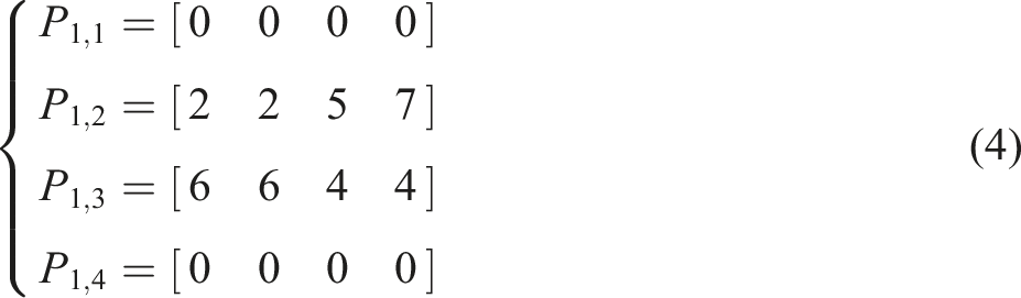
For example, the movement trajectory of warp yarns through four working steps in the grid is shown in Figure 3(a), the spatial trajectory as shown in Figure 3(b), and the movement matrix of each yarn as the following formula. Example of warp yarn movement. (a) Warp yarn movement in the grid; (b) Warp yarn spatial trajectory.
Weft and normal yarn movement model
The above model can accurately control the movement trajectory of each warp yarn, giving it a very high degree of freedom and making it easy to achieve structural changes along the length of the fabric. However, to form a stable 3D fabric structure, weft yarn in the width direction and normal yarn in the thickness direction need to be added. Compared with warp yarn, the movements of weft and normal yarns are simpler. As shown in Figure 4(a), the weft yarns are inserted between the rows, and the normal yarns are inserted between the columns. The yarn insertion occurs after each weaving step. In addition, normal yarn can be inserted into the fabric as binder yarn using the movement model of warp yarn. Unlike warp yarns, binder yarns have a larger range of movement in one working step. Figure 4(b) shows the binder yarn movement in 3D orthogonal woven fabric. The binder yarn needs to move five sub-grids in one working step. Movement mode of weft and normal yarn. (a)Weft and normal yarn; (b) Normal binder yarn.
Above all, a complete weaving process includes the following four steps: step 1, the spindle carries the yarn from the weaving position to the empty position; step 2, the yarn back to the weaving position; step 3, inserting weft yarn or normal yarn; step 4, tightening the yarn. 3D fiber preforms can be formed by repeating this weaving process.
Structure element
3D woven fabric structures are classified into three scales: micro-scale of yarn, meso-scale of fabric unit cell, and macro-scale of the fabric. The design method based on yarn movement has a very high degree of freedom, resulting in diversity in the fiber structure of preform. The fabric unit cell is the regular repeating weave pattern in the axial directions and the smallest weave repeat, 22 which is the key factor representing the weave architecture. 23 Therefore, a construction method of structure elements based on fabric unit cell is proposed to better design and control the movement of yarns.
Construction of structure element
The structure element is the smallest unit of fabric structure formed within one weaving step, which includes the movement of all yarns at the weaving position, and reflects the relationship between the weaving process and fabric structure. Figure 5 shows the structure element in a grid and space. The green shaded area in Figure 5(a) refers to the range of a structure element, and Figure 5(b) represents the spatial structure of structure element. Diagram of structure element. (a) Structure elements in grid; (b) Structure element in the space.
The structure element contains the movement trajectory of the yarn in the two working steps. According to the warp movement model, the yarn has nine movement modes when it leaves the weaving position in the first working step. However, there is also the case that there is no yarn in the initial weaving position, so there are ten movement modes for the yarn in the structure element. Similarly, there are ten modes when the yarn returns to the weaving position in the second working step. Figure 6 shows the yarn movement modes in the structure element. The dashed lines indicate that the spindle leaves the weaving position in Figure 6(a), and the solid lines indicate that the spindle returns to the weaving position in Figure 6(b). Yarn movement mode in structure element. (a) The first working step movement mode; (b) The second working step movement mode; (c) Examples of structure element.
Similar to the yarn movement model, the structure element can also be represented by a matrix, as shown below.


Examples of structure elements.


Structure cell
The fabric unit cell is the smallest repeated area in the fabric preform structure, which can be represented by assembling the structure elements in this area. It is referred to as the structure cell in this paper. Figure 7 shows the structure cell is composed of structure elements Diagram of structure cell. (a) Movement mode; (b) Spatial Structure.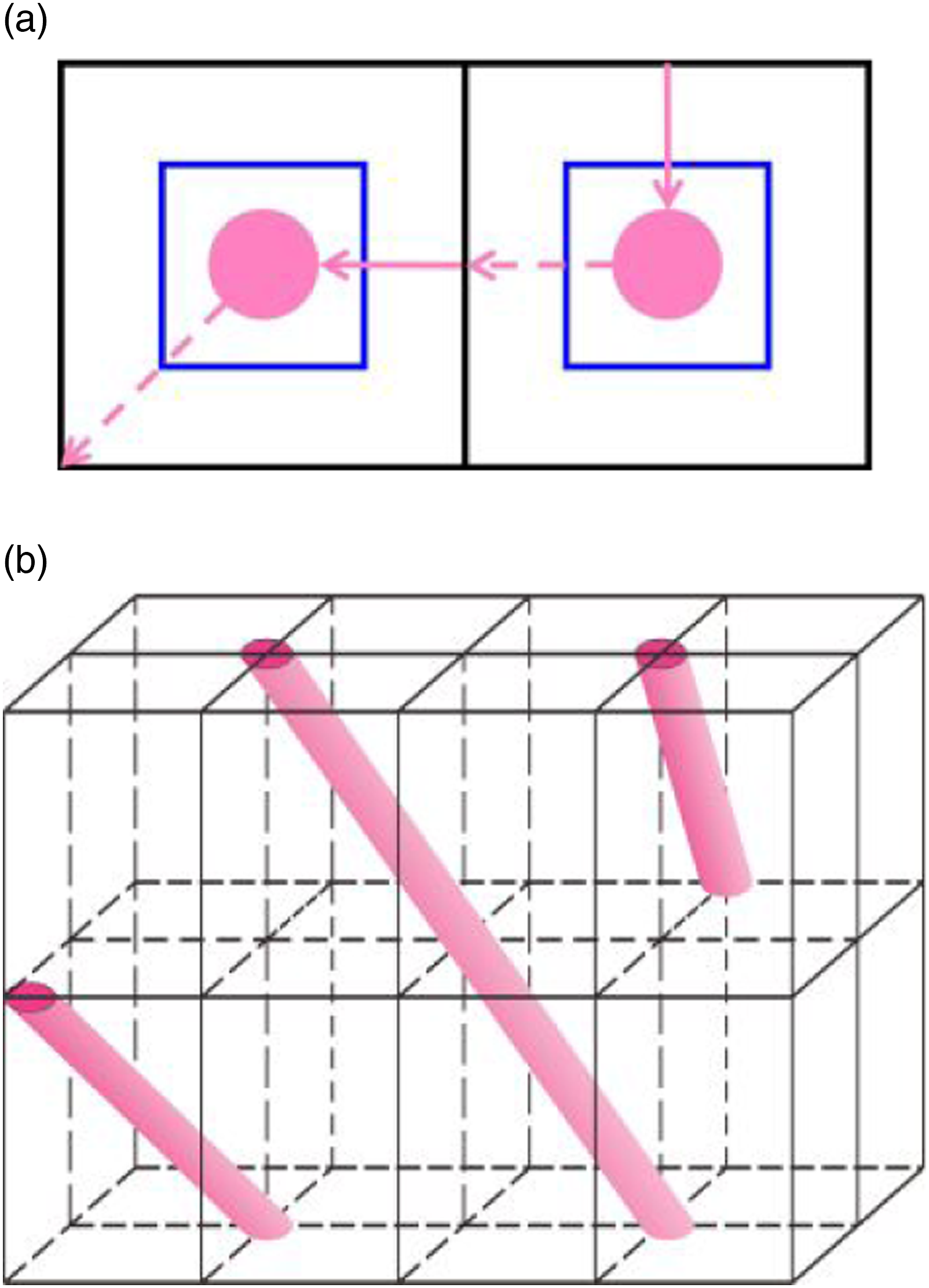
3D woven fabric and 3D braided fabric are taken as examples to illustrate the establishment of structure cells. In the 3D layer-to-layer angle interlocking woven fabric, the warp yarns are arranged along the length direction of the fabric and interweaved with the weft yarns. The movement modes of the two weaving steps are shown in Figure 8(a) and (b). In the first weaving step, the warp yarn in the odd columns moves according to mode 3D layer-to-layer angle interlocking woven fabric. (a) The first weaving step movement mode; (b) The second weaving step movement mode; (c) Structure cell; (d) Fabric unit cell.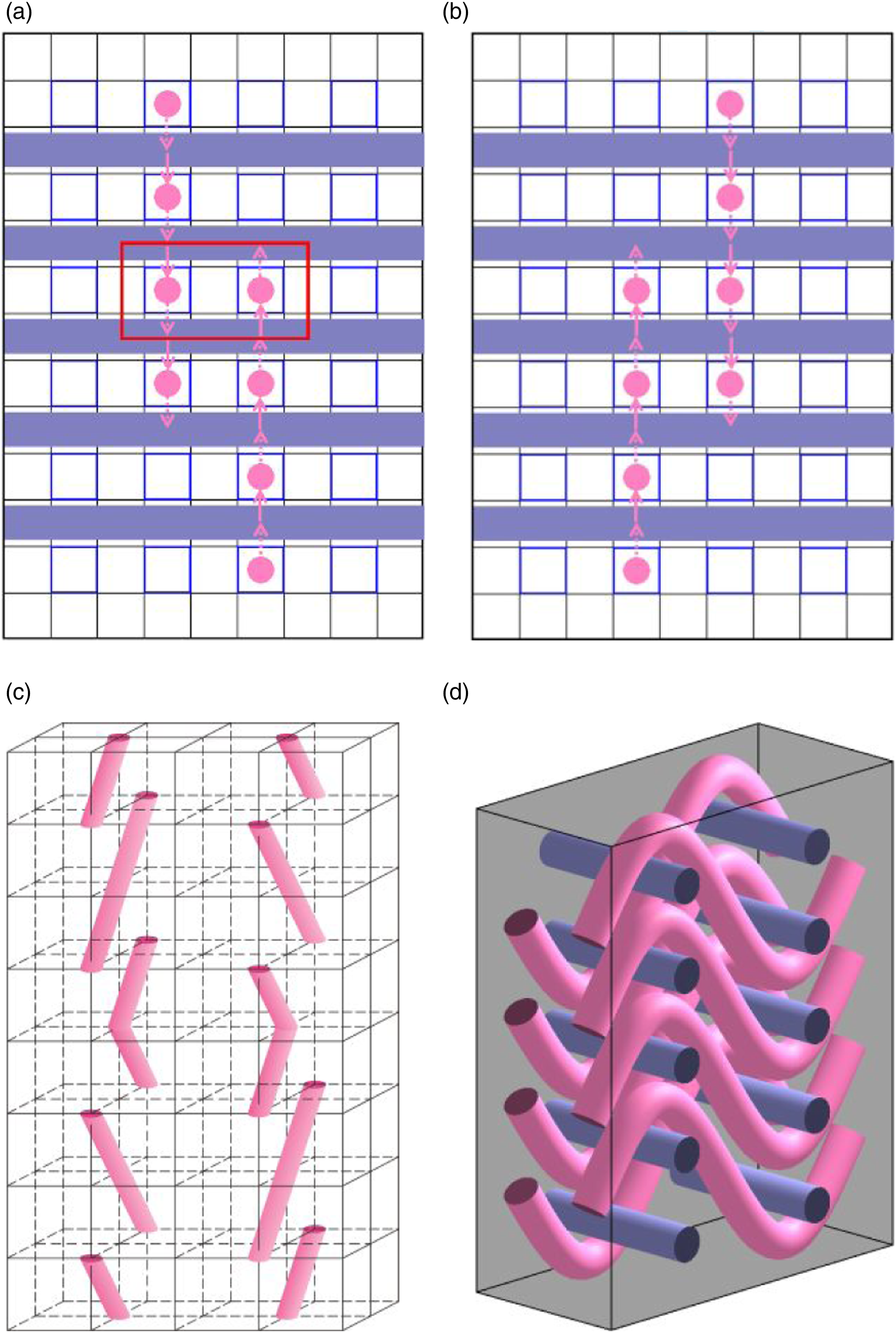
In the 3D braided fabric, only the braided yarns are involved in braiding, and no axis yarn is inserted. Therefore, the braided yarn can be represented by warp yarn, and its arrangement and movement modes are shown in Figure 9(a). The braiding repeat includes four working steps, and the shaded arrows show the direction of yarn movement in the working step. The fiber structure of 3D braided preform can be obtained after some braiding repeats. Take the structure elements in the red rectangular box in the figure as an example, and their movement modes in the four working steps are 3D braided fabric. (a) Working steps; (b) Structure cell; (c) Fabric unit cell.
Digital implementation
Based on the mathematical model of yarn movement and the construction method of the structure element, the software package is developed using wxPython and OpenGL technology, where wxPython was used for design interaction and GUI(Graphical User Interface), and OpenGL was used for the visualization.
Preform design
As shown in Figure 10, the window is the operation interface of the 3D weaving process proposed in this paper. The right area of the window is the parameter area, where the count, layers, density, and other parameters of the warp and weft yarns can be set. The left area is the design area, which shows the arrangement of warp yarns at each work step. Different fabric structures are designed in the work step area by moving the warp yarn cross-section according to the movement mode. As mentioned above, the number of working steps is determined by the number of weft insertions. Generally, the weft yarn is inserted once every two working steps, and multi-layer weft insertion is considered as one weft insertion. The number of work steps can be expressed by the following formula Design interface of 3D textile preform.
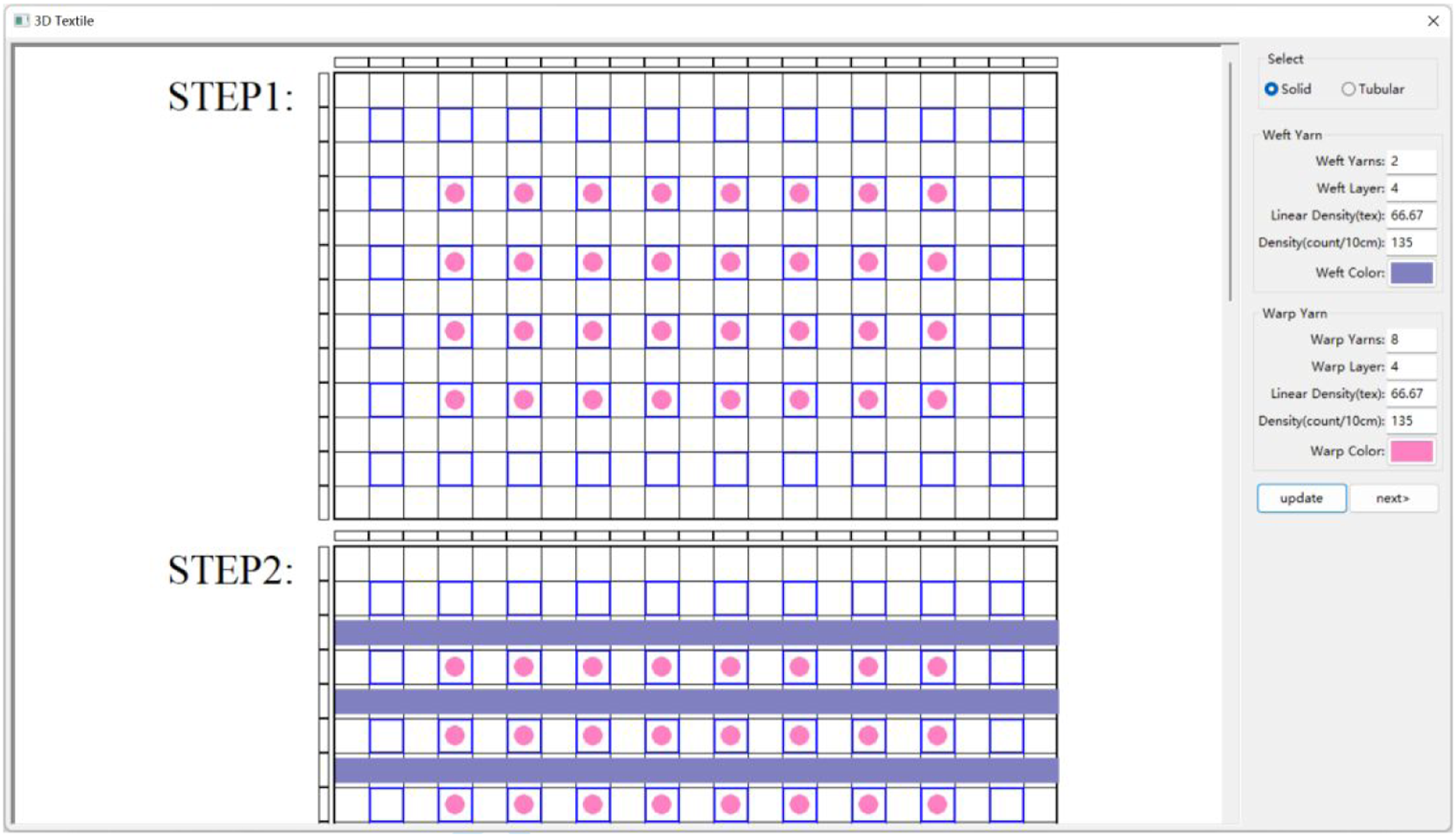
According to the warp movement mode, the warp yarn can only move one sub-grid in one working step to ensure that the warp yarn can return to the weaving position in the next working step after leaving the weaving position. In addition, in order to avoid overlapping with other warp yarns, a principle must be followed that there is at most one yarn in any position. However, in some 3D fabric structures, the warp yarn moves more than one sub-grid between two weft insertions.
For example, the 3D angle interlocking woven fabric introduced in the previous section requires the warp yarns to move four sub-grids between two weft insertions, resulting in weft insertion occurring every four working steps. This fabric is unsuitable for the established relationship between the number of working steps and the number of weft insertions. To avoid this issue, the movement range of the warp yarns is no longer limited to one sub-grid in a single working step. However, the warp yarns must return to the weaving position when weft insertion. In most cases, the yarn moves the same distance in the two working steps of one weaving step, i.e., the yarn moves n sub-grids in the first working step and also moves n sub-grids in the second working step (
The movement mode of the warp yarn in the weaving process can be represented by a two-dimensional matrix, allowing a two-dimensional array to represent the corresponding data structure. The number of rows and columns of the two-dimensional array represents the number of rows and columns of the warp yarn. After all the work steps are designed, the yarn path can be extracted from the stored position information in the array and used for fabric simulation.
Fabric simulation
Fabric simulation is the process of building a geometric model of the yarn. To model a yarn, the yarn path and cross-section must be defined. As mentioned, the yarn path can be obtained by the warp movement information. Then the spatial coordinates can be calculated by combining the information of the warp and weft density of the fabric and the yarn parameters.
As shown in Figure 11, the element is in the XYZ coordinate system. The height of the structure element is the fill yarn spacing, represented by The spatial position of yarn in the structure element.
The yarn position in the working step is defined as master node, and the yarn’s centerline can be obtained by connecting all master nodes, as shown in Figure 12(a). The most generic way to get the accurate yarn path is to interpolate between these discrete master nodes. Figure 12(b) shows the yarn path interpolated by B-spline functions. The yarn cross-section is defined as a 2D shape perpendicular to the yarn path. Various shapes have been explored, including the circle, ellipse, and lenticular shapes. In this paper, a circle shape is used for the yarn cross-section, and it is assumed that the shape is constant along the length of the yarn in order to create the model quickly. Sweeping the cross-section along the yarn path can obtain the yarn model, as shown in Figure 12(c). Combining all the yarn models together produces the idealized meso-model of the fabric, as shown in Figure 12(d). Process of building fabric meso-model. (a) Yarn centerline path by connecting the main nodes; (b) Interpolation spline of yarn path; (c) Yarn model; (d) Fabric meso-model.
The 3D fabric design method proposed in this paper has good expansibility and is intended for designing special-shaped fabric preforms. In addition to the traditional 2D and 3D woven fabrics shown in Figure 13(a) and (b), 3D braided, variable cross-sections, tubular, and other fabrics can be designed. As long as the fabric structure changes along the length direction, it can be designed using this method. When designing fabric with variable cross-section, the warp or weft yarns are added and reduced at specific working steps to change the longitudinal or transverse cross-section of the fabric, as shown in Figure 13(c) and (d). To create the longitudinal variable cross-section fabric, both warp and weft yarns are reduced in specific positions, while the transverse variable cross-section fabric only needs to reduce the warp yarns. Examples of fabric preform. (a) 2D plain woven fabric; (b) 3D orthogonal woven fabric; (c) Longitudinal variable cross-section fabric; (d) Transverse variable cross-section fabric; (e) Tubular fabric; (f) Composed of 3D woven and 3D braided fabric; (g) T-shaped cross-section fabric; (h) Honeycomb fabric.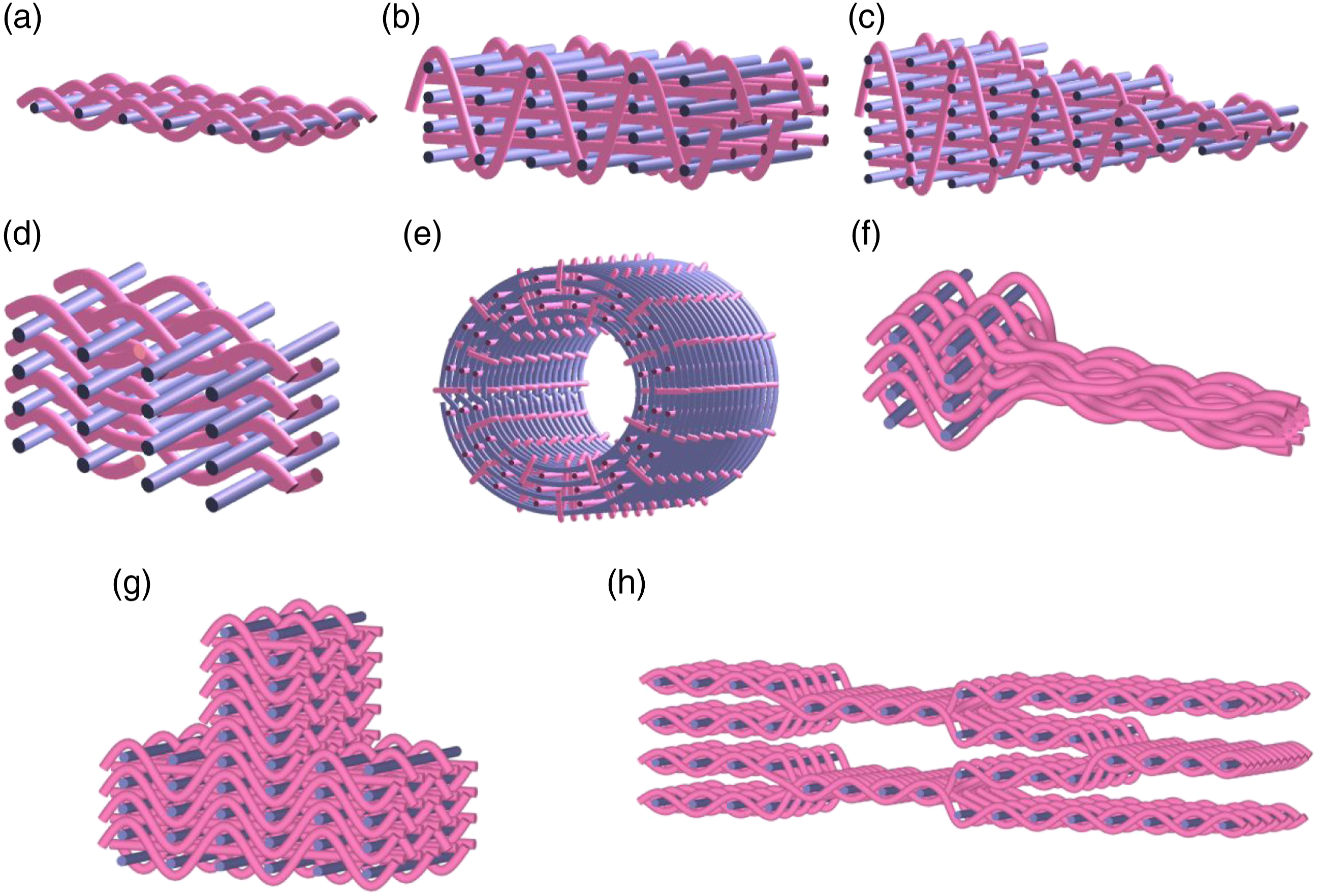
Tubular fabric is realized on the basis of three-dimensional fabric. First, designing the smallest repeat structure of 3D woven fabric. Then setting the repeat times of the fabric repeat in the tube and along the length direction of the tube. Figure 13(e) shows the tubular fabric model.
In addition, a preform composed of 3D woven and 3D braided fabric is designed as shown in Figure 13(f), which can realize smooth transition between different structures. The validity of this method is further proved by designing T-shaped cross-section fabric and honeycomb fabric.
Conclusion
3D woven fabric preforms are the main reinforcement of composite materials. In particular, the integrated special-shaped preform is crucial for expanding the application of composite materials. A design method for the 3D fabric was developed to improve the design ability of integrated preform. The method, inspired by 3D braiding, is based on yarn movement mode that controls the path of the yarns in the fabric in order to build various structures. A mathematical model of yarn movement was also developed, allowing for a high degree of freedom of movement for yarns in space. Fabric unit cells were built by assembling structure elements. Optimizing the arrangement and combination of structural elements of the preform the final 3D woven structure can be achieved by adjusting the yarn orientation and geometric features at the coupling position of different structures. A software package to digitize the proposed method and the idealized meso-scale model of the fabric was also developed based on the design data that reflects the yarn space configuration in the 3D shaped fabric.
In the future, the proposed design method will be further optimized to enable the design of more complex structural preforms, and generate a meso-model that can reflect the actual fabric. Additionally, the method will be applied to the actual weaving process and the production of preforms.
Footnotes
Declaration of conflicting interests
The author(s) declared no potential conflicts of interest with respect to the research, authorship, and/or publication of this article.
Funding
The author(s) disclosed receipt of the following financial support for the research, authorship, and/or publication of this article: This work was supported by the Tianjin Natural Science Foundation (19JCYBJC18300), National Science and Technology Major Project (2017-Ⅶ-0011-0177), Science and Technology on Advanced Functional Composites Laboratory, Aerospace Research Institute of Material and Processing Technology (6142906210406), Science and Technology Foundation of National De-fense Key Laboratory of Advanced Composite Materials (61429040403), A Multi-Scale and High-Efficiency Computing Platform for Advanced Functional Materials (22HHXCJC00007).