
Abstract
Crocheted textiles receive scarce scientific study and are at present not produced in automatized industrial scale. Computer-aided modelling and simulation offer capabilities for investigating possible technical fields of application. In this context a novel approach for modelling crocheted textiles consisting of chains, slip stitches and single crochets using a topology based and parameterized key point representation at the meso scale is proposed. According to the stitch size, yarn diameter and pattern spline interpolated models, which are free of interpenetrations up to approximately a 1/10 ratio of yarn diameter to stitch size, are generated by a developed Python program and software from the company TexMind. The models are suitable for finite element method (FEM) applications with LS-DYNA with which the mechanical properties of crocheted textiles can be studied. Exemplary simulations show anisotropic properties and homogeneous distribution of stresses in a crocheted textile. Due to the computationally simple and flexible modelling the presented approach may serve as a tool for designing planar crocheted textiles. This allows for estimation of the required yarn length and offers the prediction capabilities of simple and fast FEM simulations based on beam elements.
Introduction
In addition to the well-known surface-forming textile processes of weaving and knitting, which are used in numerous technical fields, crochet is known since the 19th century1,2 but has received little scientific attention and is not applied in the field of technical textiles. 3 The latter can be attributed to the lack of an automated production process in contrast to the other textile area forming processes. Although initial approaches to automate the manually performed crocheting process exist4,5 these are not being implemented in textile industry.
Crochet is similar to knitting in that a stable mostly planar fabric is created from a single yarn by pulling loops through existing loops and intermeshing them with the surrounding loops. In contrast to knitting general differences are the use of a single hook needle for crocheting and forming a new stitch only after the previous one is finished. 3 There are numerous crochet stitches, which differ in size and topology as well as in the number of stitches picked up on the crochet hook and passed through each other. 3 Crochet stitches correspond to a slipknot since the entire textile can unravel as soon as one knot comes loose. 2 The simplest stitches on which more complex ones are based are the chain, slip stitch and single crochet.
Generally, crocheted textiles find application in the form of clothing or as home decorations and are popular in the hobby crafting field. 6 Examples of technical application are a soft and flexible manually crocheted shell of a social robot 7 and manually crocheted artificial tendons and ligaments for a robotic hand.8,9 Furthermore, scientific applications take advantage of crochet’s various stitches and the ability to create a new loop and pull through an old one at any stitch of the textile to create complex three-dimensional structures. 10 In this regard crocheted textiles model hyperbolic planes and are used as a basis for architectural design methods.3,10–13
In order to explore further possible technical applications of crocheted textiles, those need to be modelled and researched by simulations. The modelling of textiles can generally be performed on three different scales. 14 With the macro scale the textile structure is represented as a continuum plate or membrane with the appropriate mechanical behavior.14,15 Regarding the meso scale the textile is divided into unit cells where the yarn is considered as a continuum.14,15 Within a unit cell the yarn path in the intermeshed structure can be described geometrically by mathematical functions as proposed regarding knits.15–17 Alternatively, the yarn path can be simplified with a topology based representation in which the information of the topology of the structure is suitably replicated but the curvature and the exact course of the yarn do not correspond exactly to a real textile.14,18,19 By considering the micro scale the fiber-fiber interactions within the yarn are modelled from which e.g. the actual yarn cross section can be derived.14,15
According to Kyosev’s work, 20 topology is here defined as “the knowledge of the orientation and positions of the yarns (or their axes), related to the other yarns in the same structure”. In contrast to a geometric model, a topology based one does not describe the exact curvature of a yarn segment with respect to another yarn segment but only the general topological orientation of these. This is a simplification that allows a less limited and more general use of a model, e.g. for yarns with different mechanical properties. 20
Guo et al. 3 modelled crotched patterns as stitch meshes by defining a set of tiles as unit cells with a topology based representation of different stitches at the meso scale. By assembling the tiles, it is possible to model three-dimensional crochet textiles based on input geometries as well as to generate text instructions according to the international notation of the Craft Yarn Council 21 to hand crochet those. Additionally, Capunaman et al. 2 proposed a crochet pattern generation with three-dimensional modelled surfaces as input and by considering the individual crocheting style of the crafter based on measured crocheting swatches.
Alternatively, a topology based model at the meso scale can be built by defining key points – parameterized coordinates in a three-dimensional space – along the yarn center path in a unit cell, e.g. one stitch, to reflect the characteristic topology which is an often used strategy.14,18,22 To gain a more realistic representation of the geometry of the yarn path, the key points can be adjusted. 14 This can be carried out with respect to mechanical considerations by applying internal and external forces, by geometric considerations or by spline interpolation.14,23,24
Based on such models, finite element methods (FEM) can be used for further simulative mechanical investigations of the textile and to optimize the structure, since analytical models are often insufficient due to the high complexity of the meshed fabric.14,23–26 Regarding FEM, which solves the partial differential equations numerically describing various problems by meshing a body into small elements, an implicit or explicit approach can be chosen.14,23,27 For textiles the implicit solution is suitable for small displacements of small loop parts and static problems while the explicit one is more frequently used and is suitable for large deformations and nonlinear processes at short timescales.14,27 Various elements exist in commercial FEM software, in which a body can be discretized by meshing, that significantly affect the properties of the model and the simulation. 27 These range from trusses and beams as simplified elements, which are often used for simulations of textiles with relatively low computing time, to solids as three-dimensional elements without simplification in terms of degrees of freedom.24,27,28 In addition, a material type, in case of textiles often an elastic one, must be assigned to the meshed model.14,15,18,23,26,27 Lastly, to investigate the mechanical behavior of a modelled textile via FEM boundary conditions must be defined to simulate the test setup. 26
Here, a novel simple modelling approach of crocheted textiles using topology based, spline interpolated key point models of chains, slip stitches and single crochets at the meso scale in the framework of the TexMind software package 29 is presented. Also, the suitability of the models for FEM application using the commercial software LS-DYNA, which is popular for explicit calculations, 27 is investigated to enable the exploration of technical applications of crocheted textiles.
Materials and methods
Materials
The textiles were crocheted with a commercial 4 mm crochet needle and yarn with an approximate diameter of 0.5 mm. To compensate for the inaccuracies of hand crocheting, five textiles each were produced and measured in terms of yarn length after unraveling. Photos were taken by a Canon 1300D camera with Tamron SP AF 17–50 mm F/2.8 XR Di II LD aspherical lens and microscopic images were made by a digital microscope Camcolms2 (Velleman, Gavere, Belgium). A laptop with an Intel processor i7-6820HQ at 2.7 GHz and 16 GB RAM was used for modelling and FEM simulation.
Methods
As basis of the topology based key point model the parameterized coordinates of the center yarn path were defined as a unit cell for each stitch. The parameters depend on the distance between stitches (L) in a row, which directly correlates with the length of the stitch, and on the yarn diameter. Additionally, the stitch height (H) and depth (D) can be set as an input (cf. Figure 2). A tuple consisting of three coordinates according to the space directions corresponds to one key point. By adding L to one dimension of the coordinates of a stitch, the stitch can be shifted spatially in the corresponding direction. Following this principle, a stitch row can be created as a list of key points. To model a two-dimensional textile, further rows with a distinction made according to left and right orientation can be formed according to the same principle. These can then spatially shifted and rotated so that the loops of the individual rows intermesh in a correct manner. The sequence of key points in the list corresponds to the sequence of formed stitches from which the textile is constructed according to the process of manual crocheting.
Python 3 was used for programming the key points of chains, slip stitches and single crochets with the corresponding shifting operations to build a topology based representation of the yarn path with the number of rows and columns as well as the type of stitch used for each row as further inputs. Programming of the key points is based on the freely available Python library 30 maintained by TexMind. As basic steps, the developed Python program builds the required stitch rows as lists of the key point lists of the stitches in a row, which are shifted according to their position in the row by adjusting the key points. The stitch rows are then shifted in space according to the sequence of the stitches in the textile by adjusting the key points and are then combined into a list. This list contains the key point course of the yarn path and is stored as the generated model with the information of the yarn diameter in comma separated values (CSV) files for subsequent further processing.
Spline interpolation is then performed to obtain a more realistic yarn path. In this regard Kochanek-Bartels splines
31
can be used, which allow adjusting the spline course between two points pi and pi+1 by configuring the tangents di and di+1 based on three parameters. The tension (t) manipulates the tangent vector length, the bias (b) alters the direction and by the continuity (c) the sharpness of change between the tangents is affected. Accordingly, it is possible to calculate the tangents as follows


Software from the company TexMind can be used for spline interpolation and for extruding the yarn according to the defined diameter to obtain a three-dimensional model. If the model is only used for visualization, the freeware Textile Viewer from TexMind 32 can be used to generate images of the spline interpolated three-dimensional model. If further investigations are to be performed with the model, the TexMind Warp Knitting Pattern Editor (WKPE) 33 is appropriate since it also provides export options to STL files or to common FEM tools.
In this regard the “LS-Dyna Beams” export option was used to gain a meshed beam model with fixed element length of 1 mm – consequently the key points are not necessarily used as nodes – and a static as well as dynamic friction coefficient of 0.3 in LS-DYNA. By using LS-PrePost, 001-ELASTIC was assigned as material keyword and 1.497×10⁻⁴ kg/m3, 1.985×10⁷ N/m2 as well as 0.3 were defined for the density, Young’s modulus and Poisson ratio, respectively. According to the topology approach of the model, mechanical properties are added during the refinement of the model for the FEM investigation and are only considered there. The contacts were handled by the AUTOMATIC_GENERAL card with 20% as the viscous damping coefficient (VDC), checking for penetrations by shortest diagonal (PENCHK) and soft constraint formulations (SOFT). Additionally, a global system damping of 0.5% was defined in the DAMPING_GLOBAL keyword by assigning 0.005 to VALDMP.
For the first simulation, a displacement in column direction, a ramp was defined by three points (0|0;1|–1;1.1|1) and used by the BOUNDARY_PRESCRIBED_MOTION_SET keyword with a scale factor of 11.7 and degrees of freedom according to the direction of motion. Resultingly, the displacement of the virtually pulled nodes is 11.7 mm and the simulation time is set to 1.1 s. These nodes are selected at the appropriate outer edge and are defined by BOUNDARY_SPC_SET with regard to the necessary degrees of freedom. With a restriction of all degrees of freedom, the nodes on the respective other side of the textile are fixed in the same way. Secondly, regarding simulating the displacement in the direction of the stitch rows the same ramp was used but with a scale factor of 2.1 and a node set at the right edge of the textile for the prescribed motion. Respectively, the left edge of the textile was virtually clamped and restricted in motion. The LS-DYNA SMP double solver was used in connection with LS-Run for calculating the simulations.
Results and discussion
Model structure
The developed method of topology based modelling of crocheted textiles at the meso scale is illustrated in Figure 1 considering an exemplary textile, of which a photograph is shown in Figure 1(a). As a first step of modelling, the structure of the crocheted textile is analyzed according to the sequence of formed stitches starting from the bottom left corner. Based on a symbolical representation as depicted in Figure 1(b) the sequence of the stitches as well as the yarn diameter and L of the hand-crafted textile are provided as input for the developed modelling Python program. This calculates the sequence and positions of the key points shown in Figure 1(c), which represent the topology based information of the yarn center path. In order to display a more realistic yarn path considering the diameter, the key points are transferred via the generated CSV files to the TexMind Viewer or WKPE to perform a spline interpolation and to generate a three-dimensional model as shown in Figure 1(d). With the WKPE and the LS-DYNA keyword file export, beams with a fixed element size can be chosen to gain a meshed FEM model with then added mechanical properties. The model can be visualized with LS-PrePost like in Figure 1(e) and (f). Modelling steps of a crocheted textile consisting of four chain stitches in the bottom row, two rows of single crochet and a row of slip stitches on the top. (a) Photograph of a hand crocheted sample with an average stitch length (L) of 5 mm and an approximate yarn diameter of 0.5 mm; (b) Abstract representation according to the international symbols of the Craft Yarn Council; (c) Topology based key points of the center yarn path with their sequential connection set by the developed Python script; (d) three-dimensional model with spline interpolated yarn path generated by TexMind Viewer; (e and f) FEM model, generated by the “LS-Dyna Beams” export of the Warp Knitting Pattern Editor (WKPE), in LS-PrePost with beam center path and volume filled beams, respectively.
By comparing Figure 1(a) with 1(d) or 1(f), it is noticeable that the model is not an exact replica of the geometry of the yarn path, especially with regard to the left and right edges. This is because the model is based on an idealized yarn path and does not consider the internal forces and the deformation of a stitch by the neighboring stitches. A topology based modelling approach was chosen because it allows a fast and flexible geometry generation while realistic deformations of the modelled textile can be subsequently simulated by FEM.34,35 The flexibility lies in the simplicity of a key point model and in having only a few constraints and relations to program.20,36 Accordingly, L specifies the basic distance between two stitches in a row (in x-direction) as well as the length of one stitch. The parameter H can be defined as the height of the stitch in y-direction as well as the parameter D as the depth of a stitch in z-direction. From these basic parameters, the relative positions of further key points can also be derived according to a realistic yarn path. Figure 2 shows relevant key points using the simple example of slip stitches. Key point representation of slip stitches with indicated basic points of a unit cell and with shaping parameters (L, H and D) of the stitch shown in red. On the left side two slip stitches, distinguished by “a” and “b”, are illustrated in the x-y-plane and on the right side slip stitch “a” is shown in the x-z-plane.
Based on the in Figure 2 indicated basic key points the following relations can be stated to define the shape of the unit cell of a slip stitch. The key point distances in the x-direction were defined as


Regarding the y-direction, the following relations can be programmed based on H


Lastly, the depth of a slip stitch is related to the key points 3a and 5a

After defining the key points of a unit cell, a topology based crochet model can be assembled by moving and rotating unit cells of stitch types and transitions between rows in space as exemplarily presented with single crochets in Figure 3. Structure and arrangement of unit cells with connection key points marked by blue triangles and squares using a transition between two rows of single crochets as an example. The displayed stitches are based on an L of 5 mm and a yarn diameter of 0.5 mm and are shown on top as connected key points and at the bottom as spline interpolated TexMind Viewer representations. (a) Unit cell of a single crochet with a crochet direction to the right. (b) Unit cell of a corresponding transition, partially consisting of a chain stitch, between two rows of single crochets. (c) Unit cell of a single crochets with a left orientation. (d) Model of a part of a crocheted textile composed of the unit cells shown in a to c.
As can be derived from the blue markings in Figure 3, the transitions between the unit cells, namely the drawn connection between the similarly marked key points, are created by their order and appropriate placement in space. Regarding the positioning of the unit cells, it must be ensured that the loops of different unit cells are suitably intermeshed with each other. This is achieved by parametric spacing between unit cells and parametric positions of key points within a unit cell, depending on the L, H and D. Based on this simple modelling approach without further interrelationships between the loops, the developed Python program can be easily extended with other crochet stitch types by defining more parameterized key points for these accounting for the spatial arrangement of the loops. Due to the parametric description, textiles can be modelled in various sizes from any combination of rows of slip stitches or single crochets, providing a flexible and rapid tool for visualizing crochet structures as well as generating geometry for FEM.
Model analysis
A closer comparison of a more complex crocheted textile and the corresponding model is illustrated in Figure 4 with a colored representation of the rows to better distinguish the stitches. It is to mention that this representation causes small irregularities in the yarn course at the transitions of the color change, because the representation is divided into several yarns, making it unsuitable for FEM application. Modelling of a crocheted textile with a yarn diameter of approximately 0.5 mm and an L of about 5 mm consisting of 10 stitches per row with the following sequence of rows counted from the bottom: a row of chains, two rows of slip stitches, two rows of single crochets, one row of slip stitches, three rows of single crochets and lastly a row of slip stitches. (a) A photograph of the hand crocheted textile with the start point in the bottom left corner and an open loop at the end in the upper left corner. (b) The respective topology based spline interpolated model visualized by the TexMind Viewer with different colors per rows. (c) Microscopical magnified section of a slightly larger lower loop of a single crochet marked by black dots. (d) Identical section of the model with a marked bottom loop of a single crochet in the middle corresponding to the marked one in c. (e) Microscope image of right slip stitches built on left single crochets, from which one upper loop is marked with black squares, from a section of the back of the hand crocheted textile. (f) A section of the back of the model identical to e with an also by black squares marked upper loop of a single crochet.
By comparing Figure 4(a) and (b) it is evident that the model is longer in width but smaller in height. This can be attributed to the yarn tension during crocheting, which pulls the loops tighter and thus stretches the textile in height while narrowing it in width which is not considered in the topology based modelling approach. This lack of contraction of the hand crocheted loops in the model is the main cause of the visually different representation for the same topology. Thus, regarding the geometry of the yarn path as it is apparent from the comparison of Figure 4(c) and (d), the model corresponds more to the irregularly wider lower loop of the single crochet where probably insufficient yarn tension was applied during its creation.
Figure 4(e) and (f) display a section from the back of the textile in the same area as Figure 4(c) and (d) as can be seen by the green single crochets and turquoise slip stitches visible in 4(d) and 4(f). Regarding the intermeshing of those it is observable that the loops of the slip stitches were pulled through the single crochets under the marked upper loop during assembly. In crocheting it is also a viable technique to pull the loops of a new row through the legs of an upper loop of the previous row, which would correspond to in between the yarn segments marked with black squares. This is not implemented in the current version of the modelling Python program but is planned to be added in the future by defining new unit cells of stitches with an appropriate yarn path for this alternative intermeshing.
The developed Python program also offers the possibility to estimate the required yarn length for a modelled crocheted textile in a quite simple way by calculating and summing up the distances between the key points. Thus, in combination with the visualization and the prediction possibilities of subsequent FEM simulations the program can also be used as a tool for the design of planar crocheted textiles. Generally, in a design process such modelling and simulation is known to enhance productivity. 25 In this context the low computational cost of the topology based key point model is advantageous and benefits the respective design processes. 24
Based on the key point model shown in Figure 1(c) the length of yarn required for the crocheted textile is calculated to be 700 mm. This is equivalent to the length of the meshed beam model consisting of 700 elements of 1 mm length. In comparison, the required yarn length for a hand crocheted textile with the same dimensions, shown in Figure 1(a), was measured as (533 ± 32) mm. Regarding the textile shown in Figure 3 a yarn length of 4026 mm is predicted based on the key point model and (3621 ± 110) mm is measured with respect to the hand crocheted textile. As a result, the hand crocheted textile requires a shorter yarn length with an average difference of (17 ± 8)% from the length calculated according to the model. It should be mentioned that the calculation of yarn consumption described here is very simple compared to other more elaborated methods37,38 and rather serves as a preliminary coarse estimation.
The deviation of the yarn length is probably due to the large spacing of the yarn segments of one stitch to those of another stitch in the computer model. This is particularly evident regarding the transitions of the rows at the left and right edges of the textile (cf. Figures 1 and 4). In the case of a hand crocheted textile, the yarn segments of different stitches touch each other, and the loops are tightened due to the yarn tension during crocheting (cf. Figure 4(a) and (b)), which stretches the textile’s height to a degree and results in less required yarn length per stitch. In the model, the yarn tension applied during production of the textile cannot be factored in directly. By modelling textiles of different stitch densities with smaller or larger stitches while using the same yarn diameter the effect of different yarn tensions can be taken into account. In this regard the distances between yarn segments are intentionally chosen as large as possible to enable a variation of the stitch size in relation to the yarn diameter in a small range, while avoiding interpenetrations of yarn segments.
Such intersections, for example depicted in Figure 5(d), of the volumes of adjacent yarn segments can occur despite correctly defined distances among the key points. This is because according to the topology based modelling approach the interpolated curve between key points forming a yarn segment is not precisely defined.20,36 Besides the incorrect visualization, interpenetrations need to be avoided, because they negatively affect FEM simulations and determine the quality of a model.23,39 In this regard the generated FEM model presented in Figure 1 was investigated with respect to the number of interpenetrations depending on L as the stitch size, from which H and D were derived, and the yarn diameter. The effect of the beam element length (BEL) on the number of interpenetrations, which were counted as initial interpenetrations by the LS-DYNA solver, was also considered. Table 1 shows the results for a variation of the yarn diameter between 0.3 mm and 0.9 mm with a constant L of 5 mm, while Figure 5 shows the respective models with yarn diameters of 0.3 mm and 0.9 mm. Models of the crocheted textile of Figure 1 with L of 5 mm and different yarn diameters. (a) Yarn diameter of 0.3 mm (yarn diameter to stitch size ratio (YDSSR) of 3/50). (b) Yarn diameter of 0.9 mm (YDSSR of 9/50). (c) Enlarged section from the back of the model depicted in a (YDSSR of 3/50). (d) Enlarged section from the back of the model depicted in b (YDSSR of 9/50) with interpenetrations marked by blue ellipses. Dependence of the number of interpenetrations on the yarn diameter and beam element length (BEL) with a fixed L of 5 mm. Initial interpenetrations were detected by the LS-DYNA solver during computation of a simulation with a model generated equivalent to the crocheted textile of Figure 1.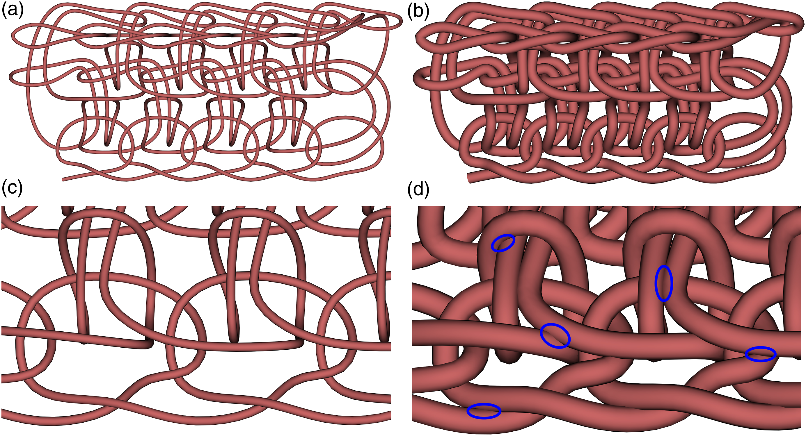

From the data presented in Table 1, it is evident that a larger yarn diameter to stitch size ratio (YDSSR) results in a higher number of interpenetrations, regardless of the tested BEL. This is also visible in Figure 5 and corresponds to real textiles, where thicker yarns also require larger stitches. To increase the range of interpenetration free ratios of yarn diameters to stitch sizes, adaptive adjustment of the key point positions depending on the yarn diameter could be added. But this would significantly increase the complexity of the modelling approach and would only be possible to a limited extend without influencing the stitch size. However, regarding the generation of interpenetration free crochet models for FEM simulation an appropriate YDSSR should be selected ranging up to about 1/10.
Concerning the number of interpenetrations of the FEM model, the BEL must also be considered. If the beams are too long, as is the case with 1.5 mm (cf. Table 1), interpenetrations occur even with 3/50 YDSSR. Interestingly, overly small BELs also result in more interpenetrations above a YDSSR of 6/50. This is presumably due to an increasing number of beam elements which are counted at one interpenetration as elements involved in this interpenetration, especially if the BEL is less than the yarn diameter. In this context, based on the results shown in Table 1, it can be assumed that an appropriate BEL is between 0.3 mm and 1 mm.
The chosen topology based modelling approach embodies a compromise between simplicity of calculation, suitability for FEM applications and realistic representation. This approach differs from other modelling approaches of crocheted textiles presented in scientific literature. On the one hand, Guo et al. 3 aimed to create a realistic representation of crocheted textiles and provided instructions to craft these. They can be generated by an automated computation of the type and position of crochet stitches based on a library of tiles according to input geometries. Technically, the structure of unit cells differs since Guo et al. defined it as a region of interconnecting yarn segments from different stitches rather than an individual stitch as defined here. In comparison with the topology based approach presented here a more realistic representation of the geometry of the yarn path is achieved by Guo et al., where the model’s suitability for FEM was not examined. 3 On the other hand, Capunaman et al. 2 focused on generating instructions for hand crafting of crocheting patterns through a top-down approach based on input geometries and the crafter’s individual crocheting style without modelling the yarn topology of stitches. Especially the latter clearly distinguishes their approach from the topology based modelling at the meso scale.
The topology based model of crocheted textiles proposed here corresponds in its approach mainly to models of knitted fabrics for FEM applications, for example based on key points14,18,19 or on alternatively defined unit cells.23,24 For instance, Kyosev 18 created a topology based model of weft-knitted textiles using a similar key point approach and then meshed it into 8-node brick elements to study deformation during displacement of nodes with LS-DYNA. A general difference to the key point representation of knit stitches is that crochet stitches require a higher minimum number of key points for a unit cell due to their more complex topology.
Finite element method application
Regarding FEM application of the model, the approach of a topology based and not completely geometrically accurate yarn path is to be seen as a simplification in the context of an idealized model.22,27 Generally, simplifications such as the representation of yarns as linear elastic cylinders at the meso scale, are common and necessary for FEM models especially regarding computation time.14,24–27
The FEM simulation depicted in Figure 6 is to be seen as an example of application and shows the possibilities offered by the proposed modelling approach to research the properties of crocheted textiles. With a calculation time of less than 10 min, such simple simulations after rapid topology based modelling are appropriate for designing crocheted textiles for technical applications in the future. Displacement FEM simulation in column direction of the modelled textile of Figure 1 at four indicated time frames. The fringe plots denote the effective stress (von Mises stress) with Pa as the unit of the respective scale. The lower nodes of the chain stitches marked with white dots in the first frame are moved downward with a constant velocity of 11.7 mm/s over 1 s and the nodes of the slip stitches marked with red dots in the first frame are fixed in position.
By the displacement of chain stitches the deformation of the textile and the distribution of the resulting stress in the textile can be observed in Figure 6. After 1 s, the stretched textile resembles the characteristic hourglass shape of knitted textiles in a tensile test, as e.g. depicted in Ref. [40]. However, the lack of deformation of the upper right transition from the single crochets to the slip stitches is a further indication of the overly large defined transitions and the need for future adjustment of the corresponding key points.
At the beginning of the simulation, the von Mises stresses in the beams of the downward moving chain stitches are relatively high. They are not yet touching the meshes of the single crochet row above as can be seen in Figure 6 at 0.1 s. As the simulation progresses, the stresses distribute evenly throughout the crocheted textile and decrease at individual beams (cf. 0.4 s and 0.7 s). Noticeably, the transition from chain stitches to single crochets at the bottom right corner remains slightly more stressed throughout the simulation. In future research, it must be investigated whether this is due to inadequately placed key points of the transition or possibly represents a weakness in the crocheted structure.
As a further example of an FEM application of the modelled crocheted textile of Figure 1, a displacement in the direction of the stitch rows is depicted in Figure 7. Here, the stresses induced by the displacement of the beams of the right side affect the stitches of the neighboring column after a relatively small displacement. For instance, the indicated displacement of 1.17 mm is equivalent to the displacement after 0.1 s of the first simulation shown in Figure 6. Consequently, the stress propagates slightly faster in the textile if pulled in the direction of the rows, however, it also distributes evenly. This is probably due to the stitches of the model being closer to each other in the direction of the rows. Such anisotropic behavior as evident in the simulations is also observed in knits and other textiles.26,41 FEM simulation of displacement in stitch row direction of the in Figure 1 modelled crocheted textile. The fringe plots denote the effective stress (von Mises stress) with Pa as the unit of the respective scale. Red dots mark the virtually clamped nodes of the left side in the first frame, whereas the nodes moving with a constant velocity of 2.1 mm/s are marked by white dots in the first frame. The displacements are indicated under the frames.
Conclusion
With the developed Python program, which sets the key points of the yarn center path according to a user defined stitch size, radius and pattern, a crocheted textile consisting of chains, slip stitches and single crochets can be modelled topology based at the meso scale. Besides a simple visualization, the model can be transferred into an FEM tool like LS-DYNA after a spline interpolation by using the TexMind WKPE. A relatively homogeneous distribution of stresses along with a realistic deformation and anisotropic properties could be observed by the exemplary FEM simulations performed based on a modelled basic crocheted textile.
Due to wide spacing between yarn segments interpenetrations can be avoided, while the yarn radius and stitch size of the modelled textile can be freely set by the user within a range of up to approximately a 1/10 ratio. The model allows an estimation of the required yarn length with an average difference of (17 ± 8)% compared to a hand crocheted textile. Thus, together with rapid FEM simulations, e.g. based on beams, the computationally simple and flexible modelling approach can be seen suitable for design processes of planar crocheted textiles.
The novel modelling presented provides a reasonable approach for the simulative study of crocheted textiles in the context of possible applications in the field of technical textiles even though future improvements are needed. Especially the key points of the transitions between the stitch rows must be adjusted to obtain a more realistic representation. Additionally, an extension of the Python program is planned to include more stitches as well as to perform more sophisticated FEM simulations regarding the mechanical properties of crocheted textiles.
Footnotes
Declaration of conflicting interests
The authors declared no potential conflicts of interest with respect to the research, authorship, and/or publication of this article.
Funding
The authors disclosed receipt of the following financial support for the research, authorship, and/or publication of this article: The study was partly funded by the German Federal Ministry for Economic Affairs and Climate Action in the scope of the ZIM project KK5129701PK0 and by the Deutsche Forschungsgemeinschaft (DFG, German Research Foundation) – 490988677 – as well as the University of Applied Sciences Bielefeld.