
Abstract
The effect of different concentrations of epoxy surface coating treatment on the thermal and mechanical properties of kenaf fiber reinforced recycled poly (ethylene terephthalate) (RPET) composites was studied. Silane-treated kenaf fibers (SKF) were epoxy-coated with optimized coating concentrations (in the ratios of 1:4, 1:5, and 1:6 epoxy to acetone solutions) to improve the thermal degradation/decomposition resistance and interfacial bonding with RPET matrix. The different epoxy coated-silane treated kenaf fibers 1:4 ESKF, 1:5 ESKF, and 1:6 ESKF were compounded with RPET at an optimized temperature of 240°C, and their constituents’ composites KF/RPET, 1:4 ESKF/RPET, 1:5 ESKF/RPET, and 1:6 ESKF/RPET were subjected to thermal, mechanical and microstructural investigation. The obtained results showed some remarkable effects of epoxy concentrations on the chemical and surface structures of the treated fibers. Thermal properties of both ESKF and ESKF/RPET composites were more stable and improved with different concentrations of epoxy treatment compared to the untreated counterparts. 1:4 ESKF and 1:5 ESKF were the most thermally stable with onset degradation and DTG decomposition temperatures of 331.6°C and 381.7°C, and 324.0°C and 388.7°C respectively. Mechanical properties of the epoxy-coated composites were higher and further improved with epoxy concentrations and fiber loadings compared to uncoated composites. Hence, the epoxy concentration of 1:4 gave the maximum tensile and impact properties, and at 10 wt. % fiber loading within the lower loading regions, followed by 1:5 with outstanding flexural properties. The coated-treated composites showed strong fiber/matrix bonding with no evidence of fiber decomposition compared to the untreated composites with poor fiber/matrix interaction. The current research findings are original and valid for improving the thermal degradation resistance and stability of natural fibers, and the mechanical properties of natural fiber reinforced engineering thermoplastic composites. The epoxy coated – silane-treated textile kenaf fibers reinforced with recycled PET composites have the potentials to be utilized in high-temperature industrial and engineering applications.

Keywords
Introduction
Poly (ethylene terephthalate) (PET) is a semi-crystalline and a high-temperature thermoplastic polymer synthesized by polycondensation reaction of terephthalic acid and ethylene glycol with water as a byproduct or by trans-esterification reaction between ethylene glycol and dimethyl terephthalate with methanol as a byproduct.1,2 Notably, PET has gained wide appeal as a commodity plastic due to its unique important properties. It has been adjudged the second most widely used plastic in bottles and other rigid and semi-rigid packaging containers after high-density polyethylene (HDPE). 3 It is used as a packaging material for water and soft drinks in beverage industries because of its high gas barrier properties. 3 Additionally, PET has a high glass transition temperature (78°C), 4 melting temperature (245–265°C), 5 and excellent optical clarity when compared with glass.
Despite these outstanding properties of PET and its wide appeal, the non-degradability of waste PET products has caused serious environmental pollution, and also their presence within our agricultural land has considerably reduced the fertility of the soil, thus, putting pressure on the food chain. 6 To address this problem, recycling waste PET products, which would help to address the problem of plastic pollution, has become necessary. In addition, the recycled waste PET (RPET) products could also be engineered for possible diverse applications. Thus, extensive research activities are ongoing to develop engineered composite products based on recycled waste PET products. Furthermore, to achieve this, some natural fibers such as kenaf, sisal, hemp, and jute among others are being modified for better performance as fillers in RPET-based composites.6–8
For outstanding performance, chemical surface treatments have been employed to modify the structural constituents and surface morphology of natural fibers to enhance their compatibility with polymer matrix, reduce moisture absorption, and promote fiber/matrix adhesion. In this regard, some reports have demonstrated that silanization,9,10 acetylation,10–12 benzoylation, and peroxide treatment10,13,14 improve the surface properties of natural fibers for better application performance. Overall, silane treatment has been demonstrated to be better than some other surface treatment methods in improving the interfacial property of natural fibers.15,16 Additionally, epoxy-coating of natural fibers is a new method of surface modification of natural fibers and it has shown the capability of improving the degradation/decomposition resistance of the natural fibers.17–21 Thus, Ghazter et al. 22 experimented with the effect of various viscosities of epoxy coating solutions (1:4, 1:5, and 1:6) on the physical, mechanical, and morphological properties of kenaf/epoxy composites, and obtained optimum results at 1:6 (epoxy: diluent) coating solution. Similar research studies have been conducted,23,24 and the findings are somewhat in line with observations of Ghazter et al. 22
This study explored a novel approach to applying different concentrations of epoxy coating on the silane-treated kenaf fiber for utilization as the reinforcing fillers in recycled PET composite. Thus, in this study, kenaf fibers were treated with aminopropyl silane to reduce the propensity for moisture absorption and as well enhance its adhesion property. Subsequently, the epoxy coating was applied to the fibers following an already established protocol 22 to enhance their thermal stability and chemical resistance. The kenaf fiber was chosen as a reinforcing filler because it is readily available, has a thermal degradation temperature of about 200°C, 25 and possesses better mechanical properties when compared with some other natural fibers. 26 Additionally, kenaf fiber can grow under a wide range of climatic conditions and they are cheaper when compared to some more expensive synthetic fibers.
Experimental
Materials
Kenaf fiber (KF) used was donated by the Malaysian Agricultural Research and Development Institute (MARDI), Malaysia. Epoxy resin/hardener (diglycidyl ether of bisphenol A, DGEBA) used for surface-coating was supplied by Oriental Option Sdn. Bhd., Malaysia). The diluent, acetone (C3H6O), and acetic acid (CH3COOH) used for acetylation were both supplied by SYSTERM, Malaysia. Waste poly (ethylene terephthalate) bottles (Figure 1(a)) used were obtained from garbage dump sites within UiTM and Shah Alam district, Selangor, Malaysia. Sodium hydroxide used for alkali treatment of kenaf fibers was sourced from MERCK Chemical Industry, Germany. Ethanol (C2H3OH) was sourced from RCI Labsen Ltd. Malaysia, and aminopropyl silane used for silanization was supplied by Dow Corning Chemical Industry, USA. Pictorial images of (a) Waste PET bottles (b) crushed waste PET bottles (RPET) (c) Pulverized RPET (5 mm size) and (d) pulverized RPET extrudates.
Methods
Processing of waste PET bottles
The procured waste PET bottles (Figure 1(a)), were manually sorted, cleaned by washing with water, air-dried, and chopped into smaller sizes (see Figure 1(b)) with a crushing machine. The crushed waste PET flakes were further washed thoroughly with water and industrial soap, rinsed with clean water, dried under normal temperature for 48hours, and subsequently pulverized into fine particles (Figure 1(c)) using the pulverizing machine (Fritsch Power Cutting Mill Pulverisette 15) with 5 mm Mesh size attached to its outlet. The obtained PET flakes now designated as recycled PET (RPET) were oven-dried at 70°C for 12 hours before melt-mixing (extrusion) in a twin-screw extruder and finally pulverized through 5 mm mesh size to obtain RPET polymer particles (Figure 1(d)) ready for compounding.
Sodium hydroxide (NaOH)/Silane treatment and epoxy-coating of kenaf fibers
The raw kenaf (KF) (Figure 2(a)) was first pre-treated by soaking them in a 6% NaOH solution for 1 hour. Thereafter, the kenaf fibers were retrieved and neutralized with 1% acetic acid on weight of the fabric (o.w.f.). The treated fibers were washed repeatedly using distilled water until the solution became neutral to litmus paper. The fibers were then oven-dried for 12 hours at a temperature of 70°C to obtain discolored kenaf fibers. Furthermore, to reduce the water absorption tendency of kenaf fibers before being used for composite preparation, the fibers were first surface-modified by immersion in a 1.0% concentration of aminopropyl silane solution with ethanol on the weight of fiber (1.0% o.w.f) and allowed to remain soaked in the solution for 3 minutes, after which they were retrieved and dried. Pictorial images of (a) untreated Kenaf fiber (KF) (b) Pulverized epoxy coated/treated kenaf ESKF (5 mm size).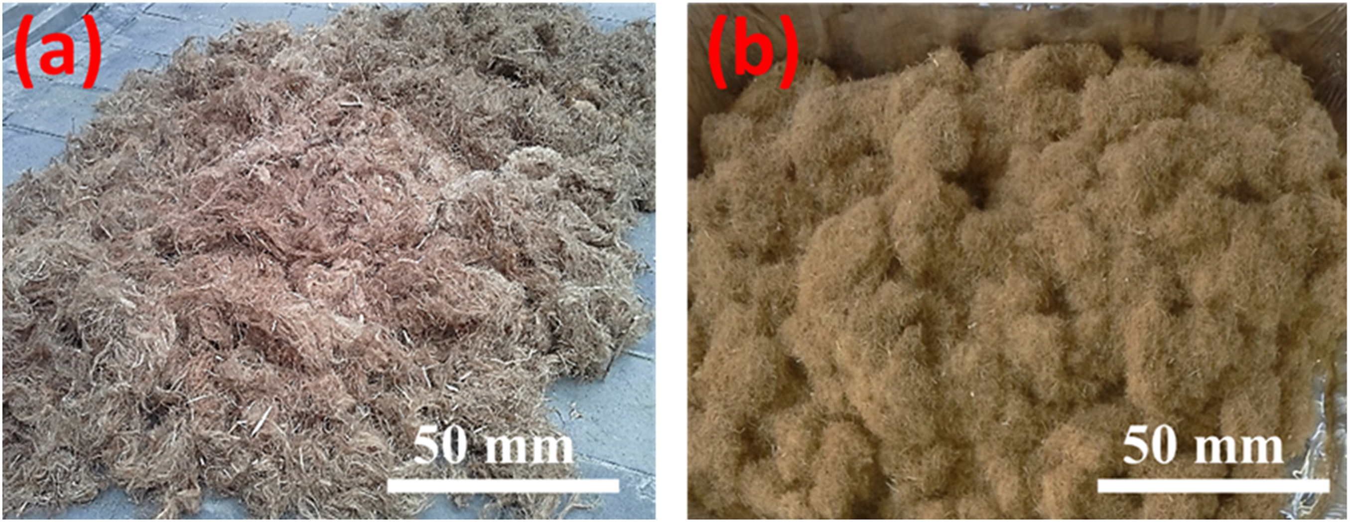
Secondly, the silane-treated kenaf fibers (SKF) were surface-coated with different solution concentrations of epoxy coating. The epoxy coating solutions used were prepared by diluting a given amount of epoxy resin with different volumes of acetone to give varying epoxy: acetone solution concentrations. Thus, three (3) different epoxy concentrations obtained from epoxy: acetone ratios of 1:4, 1:5, and 1:6 gave optimized epoxy coating solution concentrations which were used for effective coating of kenaf fibers. Then, the silane-treated kenaf fibers were immersed in the epoxy coating solutions, allowed for 3 minutes, and retrieved thereafter to obtain epoxy-coated silane-treated kenaf fibers ESKF (Figure 2(b)). Consequently, different epoxy-coated silane-treated kenaf fibers (1:4 ESKF, 1:5 ESKF, and 1:6 ESKF) were obtained, cured at a temperature of 80°C for 24 hours in an air circulated oven, and later pulverized into short fibers by passing through 5 mm Mesh size aperture using the pulverizer machine.
However, it should be noted that during the immersion of kenaf fibers in the epoxy coating solution, there was uptake of the epoxy coating solution by the kenaf fibers, and this was expressed as epoxy coating uptake using equation (1).

Using equation (1), the epoxy coating uptake by the kenaf fibers was estimated to be 48.61%.
Composites preparation
The untreated kenaf fibers (KF) and epoxy-coated silane-treated kenaf fibers (ESKF) were pulverized with a 5 mm mesh size aperture using the pulverizer machine and dried for 48 hours at 25°C before compounding with the RPET. KF/RPET composite was fabricated by mixing 5 g of KF with 95 g of RPET to produce 5 wt. % KF/RPET composite. Subsequently, 5 wt. % each of 1:4 ESKF, 1:5 ESKF, and 1:6 ESKF treated fibers were used to fabricate composites with RPET as the matrix. Thus, there are 1:4 ESKF/RPET, 1:5 ESKF/RPET, and 1:6 ESKF/RPET composites obtained. Furthermore, ESKF/RPET composites with varying fiber loadings of 5 wt. %, 10 wt. % and 15 wt. % were fabricated, via a twin-screw extruder (PRISM TSE SYSTEMS 2094) with a screw speed, time, and processing temperature of 50 rpm, 5 minutes, and 240°C respectively. The extrudates (melt-mixed) were pelletized and dried for 3 hours at 80°C before compression molding. A compression molding machine was used to produce composite sheets at an optimized temperature and pressure of 240°C and 65 kg/m2 respectively. Meanwhile, preheating, hot pressing, and cold pressing times of 2, 3, and 5 minutes respectively were employed (Figure 3). a (i) 1:4 ESKF/RPET, a (ii) 1:5 ESKF/RPET and a (iii) 1:6 ESKF/RPET composites (Extrudates), b (i) Composite board, b (ii) tensile and flexural specimens, and b(iii) drop impact tests specimens respectively.
Sample characterization
FTIR spectroscopy analyses of both untreated kenaf fibers (KF), silane-treated Kenaf SKF, and epoxy-coated silane-treated kenaf fibers (ESKF) were carried out using FTIR spectrometer (Perkin Elmer Spectrum 400, model. Perkin Elmer Inc., USA) to investigate the chemical changes in functional groups of the fibers after treatment. The samples were analyzed over spectra ranging from 4000 to 500 cm−1.
Surface morphology examination
Surface morphology examinations of the untreated KF, silane-treated SKF, and coated-silane treated kenaf fibers ESKF was performed using a Scanning Electron Microscope SEM (Hitachi TM 3030 PLUS product of Japan) at accelerating voltage ranging from 5 to 20 kV. The fractured surface morphologies of the composites were also examined using ZEISS FESEM (SUPRA 40VP). Before the examination, the samples were sputter-coated using a thin layer of platinum on a coating machine (Quorum model Q150RS, UK) to make the samples under investigation more conductive.
Thermal analysis
Thermogravimetric analysis (TGA) was conducted to determine the thermal stability and decomposition temperature of the uncoated, epoxy-coated silane-treated kenaf fibers using Thermogravimetric Analyzer type NETZSCH TG 209 F3 Tarsus Instrument following ASTM D3850 standard test method to ascertain the thermal stabilities. The temperature was scanned from 30 – 600°C at a 10 °C/min heating rate under a nitrogen environment. Differential Scanning Calorimetry (DSC) (NETZSCH DSC 200 F3 Maia model) was conducted on the KF/RPET and ESKF/RPET composites following ASTM D3418-12 standards procedure to investigate the crystallization and melting properties of the recycled PET and composites before extrusion using ASTM D3418-82 standard procedure. A temperature range of 30–300°C at a heating rate of 10 °C/min was applied. Crystallization was also carried out at a temperature range of 300–30°C using the same heating rate.
Mechanical properties determination
Tensile and flexural tests were conducted on 100 mm gauge length of uncoated KF/RPET and epoxy-coated silane-treated kenaf fibers ESKF/RPET composites specimens, to determine their tensile and flexural properties using the Universal Testing Machine (SHIMADZU Autograph Precision, AG-X Series, product of Japan) at standard conditions of 50% relative humidity, and ambient temperature of 23°C according to ASTM D638 and ASTM D790 standard procedures, respectively. The tests were performed on five different samples with dimensions of 150 mm x 13 mm x 3 mm and 150 mm x 13 mm x 3 mm at 2 mm/min and 5 mm/min crosshead speeds for tensile and flexural tests, respectively
The impact test was performed with an impact testing machine, INSTRON Dynatup (model 9250HV USA) based on ISO 180 standard testing method. Accordingly, the impact test was conducted to determine the amount of energy absorbed by the test samples, and it is a measure of the material’s toughness. For all the tests, measurements were performed on five specimens of dimensions 5 mm x 5 mm x 3 mm each was tested for all the composite samples to ensure reproducibility, and average values were recorded.
Results and discussion
FTIR spectroscopy results of untreated and treated kenaf fibers
The FTIR spectra result for untreated kenaf fibers (KF), silane-treated kenaf (SKF), and epoxy-coated silane-treated kenaf ESKF with different (1:4, 1:5, and 1:6) epoxy concentrations are presented in Figure 4 FTIR spectra of untreated Kenaf (KF), Silane-treated kenaf (SKF), and Epoxy-coated silane-treated kenaf with different epoxy concentrations (ESKF 1:4, ESKF 1:5, and ESKF 1:6).
The vibration peaks ranging from 1028 - 1730 cm−1 revealed typical broad peaks of cellulosic fibers with the presence of lignin and hemicellulose structures.9–10,13,15,16 The absorption peaks at 1634 cm−1 confirmed the presence of water molecules in the samples, and the peak at 2910 cm−1 corresponds to the C-H stretching vibration from the –CH2 group of cellulose and hemicellulose. The absorption peak at 3384 cm−1 was due to the intermolecular hydroxyl bond –OH vibration of the cellulosic structure.9–10,13,15,16
When compared to the KF spectrum, the SKF spectrum depicted a reduction in peak intensities at 1028, 1634, and 3384 cm−1, possibly due to the effect of NaOH and silane. Additionally, the absorption peak at 3384 cm−1 was found to be broader compared to untreated kenaf fiber (KF), indicating that hemicellulose, wax content, and lignin were effectively removed by NaOH and silane treatments. Furthermore, ESKF spectra show a conspicuous decrease in peak intensity at 1028 cm−1, 2910 cm−1, and 3384 cm−1. However, after treatment, a new peak was formed at 1500 cm−1 which could be attributed to the Si-C stretching bond; an indication of very good interfacial interaction between the silane coupling agent, epoxy resin, and the surface of kenaf fiber.9–10,13,15,16 A cursory look at the ESKF spectra shows a reduction in the intensity of the newly formed peak at 1500 cm−1 with an increased concentration of epoxy coating solution from 1:6 to 1:4. The observed result could be attributed to the effect of epoxy coating solution which modified the surface chemistry of the fibers, imparted hydrophobic property and thus, prepared the surface for increased interfacial bonding with the polymeric matrix.
SEM analysis of untreated and coated-treated kenaf fibers
The SEM analyses results of untreated kenaf fibers (KF), 1:4 epoxy-coated silane-treated kenaf fibers (1:4 ESKF), 1:5 epoxy-coated silane-treated kenaf fibers (1:5 ESKF), 1:6 epoxy-coated silane-treated kenaf fibers (1:6 ESKF) are shown in Figure 5 and their constituent reinforced recycled PET composites (KF/RPET, 1:4 EKSF/RPET, 1:5 EKSF/RPET, and 1:6 ESKF/RPET) are shown in Figure 15. The observations are that the untreated kenaf fibers showed a heavy presence of impurities such as pectin, waxes, etc., on the sample surfaces which might be the reason for the poor interfaces between the fiber and the matrix, and hence the low mechanical properties of the resulting composites. SEM micrograph of surface morphology of Kenaf Fiber KF, and Silane-treated kenaf fiber SKF at 500x magnifications.
The silane-treated kenaf fiber SKF surface structures (Figure 5) are cleaner and smoother compared to untreated kenaf fibers surfaces, indicating that silane treatment has removed the impurities from the fibers which has resulted in improved surface quality. The smooth surfaces of the silane-treated fiber indicate the absence of lignin and hemicellulose and also resulted in good bonding with the composite’s matrix due to the reaction between the hydroxyl groups of fibers and silanol groups which necessitated interfacial bonding between fibers and polymer matrix resulting in better mechanical properties. 15
Figure 6(a), (b), and (c) show the surface morphologies of different epoxy-coated kenaf fibers 1:4 ESKF, 1:5 ESKF, and 1:5 ESKF respectively with the presence of coating epoxy resin on fibers surfaces resulted in various degrees of increased surface areas with the epoxy concentrations in comparison with raw kenaf fiber KF and Silane-treated Kenaf fibers SKF in which the fibrils' structural surfaces were more exposed. The micrograph surfaces of epoxy-coated fibers revealed porous structures being covered by layers of epoxy resin on the fiber surface which may have played a vital role in the improved thermal stability of the coated-treated fibers and good fiber-matrix bonding. SEM micrographs of (a) 1:4 ESKF, (b) 1:5 ESKF and (c) 1:6 ESKF at 1000x magnifications respectively.
Thermal properties
TGA analysis results for kenaf fibers and coated kenaf
Thermogravimetric analyses (TGA) results for untreated kenaf fibers (KF) and epoxy-coated silane-treated kenaf fibers (1:4 ESKF, 1:5 ESKF, and 1:6 ESKF) are shown in Figure 7, the TGA data attracted from the thermograms are displayed in Table 1 TGA thermograms for untreated kenaf fibers (KF) and epoxy coated-treated kenaf fibers at different concentrations (1:4 ESKF, 1:5 ESKF 1:6 ESKF). TGA data for untreated kenaf fibers (KF) and epoxy coated-treated kenaf fibers at different concentrations (1:4 ESKF, 1:5 ESKF, and 1:6 ESKF).

It is observed that all epoxy coated-silane treated fibers have higher thermal stabilities at different concentrations of epoxy coating than uncoated kenaf fiber, which could be attributed to the effectiveness of epoxy coating as well as coating concentrations. 18 The higher onset temperatures for coated kenaf fibers (1:4 ESKF, 1:5 ESKF, and 1:6 ESKF) indicate the delayed decomposition. The uncoated kenaf KF recorded lower thermal stability with an onset degradation temperature of 297.7°C and DTG/Derivatives peak of 351.9°C compared to the coated-treated kenaf fibers. While 1:4 ESKF, 1:5 ESKF, and 1:6 ESKF showed higher thermal stabilities than uncoated kenaf with an onset degradation temperature of 331.6°C, 324.0°C, and 314.8°C respectively. The results imply that the thermal degradation resistance of kenaf fibers has been improved by surface coating treatment of the fiber with silane and epoxy resin. The silane treatment removed hemicellulose, and lignin, with other pectin contents and improved the hydrophilic characteristics of the fibers, while on the other hand, surface coating of the silane-treated fibers with diluted thermoset epoxy resin at various concentrations improved the thermal degradation and stability of the fibers. These results substantiate previous findings18–20 The present research has established that the fiber degradation and stability of coated fibers also improved with increasing epoxy coating concentration. 1:4 ESKF with the highest degradation temperature is considered the optimum concentration. The reasons might be due to the high coating viscosity of 1:4, as epoxy: acetone 1:4 dilution has the highest viscosity compared to the 1:5 and 1:6 dilution since the amount of acetone increases from 1:4, 1:5, and 1:6, hence the capability of the chains molecules of epoxy to form 3D network is reduced. The viscosity of the 1:6 concentration has the lowest coating viscosity compared to 1:4.20,22 Thus, 1:4 epoxy concentration is found to be more thermally stable, followed by 1:5 and 1:6.
From Figure 6 and Table 1, the DTG/degradation peaks for untreated kenaf are at 351.9°C, while the DTG degradation temperatures of epoxy-coated kenaf fibers 1:4 ESKF, 1:5ESKF, and 1:6ESKF are at 381.7°C, 388.7°C, and 381.2°C respectively. This indicates that the effectiveness of the coating treatment is a function of its concentration and fiber loading18,20
Composites Characterization
Effect of fiber loading
The effect of the fiber content on the properties of natural fiber reinforced composites is particularly significant since high fiber content is required to achieve the high performance of the composites. It is often observed that the increase in fiber loading leads to an increase in tensile properties. In the context of our study, 1:4 ESKF was selected to appraise the effect of different fiber loading (5 wt. % ESKF, 10 wt. % ESKF, and 15 wt. % ESKF) on the thermal properties of ESKF/RPET composites within the low filler loading regions, having observed that 1:4 ESKF (treated with 1:4 (epoxy: acetone) ratio of coating solution) was most thermally stabled.
Figure 8 presents the TGA thermograms of RPET, 1:4 ESKF, 5 wt. % ESKF/RPET, 10 wt. % ESKF/RPET, and 15 wt. % ESKF/RPET samples. Their TGA values from Figure 8 are given in Table 2. TGA thermograms for untreated kenaf fiber KF, 1:4 ESKF, RPET, and 1:4 epoxy coated-treated kenaf fiber reinforced RPET composite at different fiber loadings TGA data for KF, 1:4 ESKF, RPET, and constituent coated ESKF/RPET composites at different fiber loadings (5 wt. %, 10 wt. %, and 15 wt. %).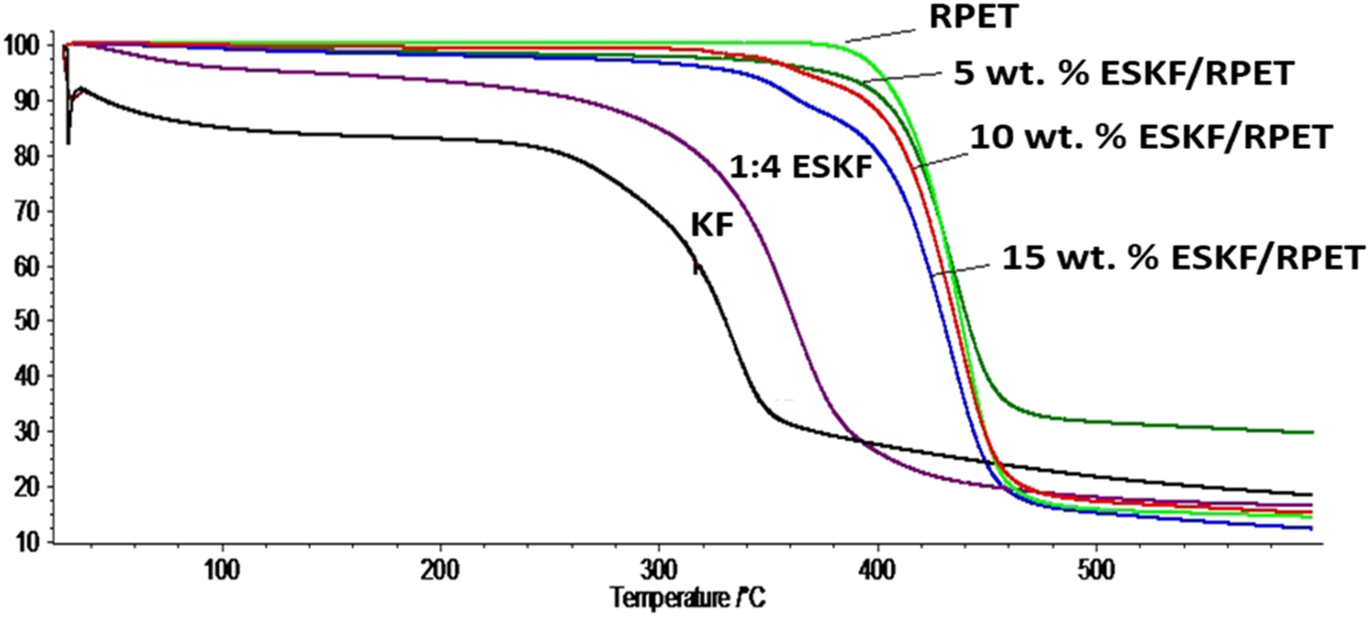
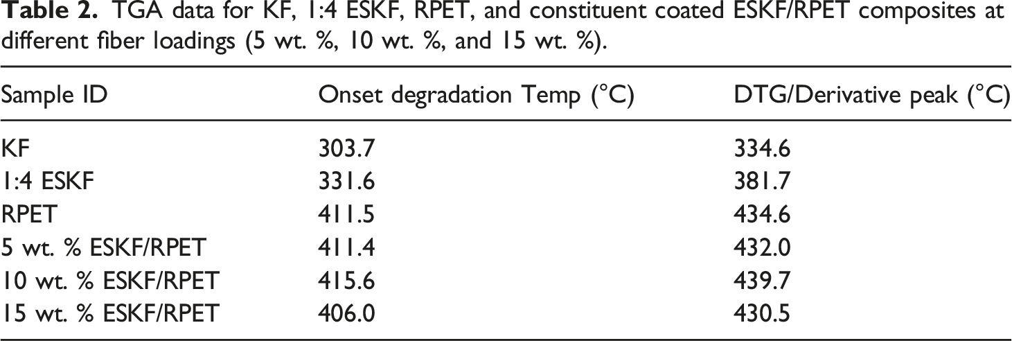
It is observed that all epoxy coated-treated kenaf fiber composites showed increased onset degradation and DTG temperatures as compared to unreinforced RPET. The incorporation of epoxy-coated silane-treated kenaf fibers ESKF into the RPET matrix increased the onset and DTG degradation temperatures of 5 wt. % ESKF/RPET, and the values increased with an increase in fiber loading up to 10 wt. % ESKF. Further increase in fiber loading up to 15 wt. % showed some decrease in values of both the onset degradation and DTG decomposition temperatures. Furthermore, the results show that 10 wt. % ESKF/RPET composite was the most thermally stable sample on account of its highest value of the onset and DTG degradation temperatures. Maximum onset degradation and DTG temperatures for ESKF/RPET composites were 415.6°C and 439.7°C respectively, which also increased with increasing fiber loading up to 10wt%, and then decreased at the increased fiber content of 15wt%. Thus, indicating that 10 wt. % fiber loading is the optimum loading as seen in Table 2. However, thermal degradation resistance decreased at higher fiber loading due to the thermal resistivity of epoxy resin which is an indication that the effectiveness of epoxy coating treatment is also a function of fiber loadings. This is also in agreement with other studies on natural fiber composites. 8
Effect of epoxy concentrations
Figure 9 shows the TGA results from analyses for RPET and its constituent KF/RPET, 1:4 ESKF/RPET, 1:5 ESKF/RPET, and 1:6 ESKF/RPET composites at the optimized 10 wt.% fiber loading. Their TGA data are given in Table 3. TGA thermograms for RPET, KF/RPET, 1:4 ESKF/RPET, 1:5 ESKF/RPET, and 1:6 ESKF/RPET composites at optimized 10 wt.% fiber loading. TGA data for RPET and constituent coated ESKF/RPET composites at different concentrations (1:4 ESKF, 1:5 ESKF, and 1:6 ESKF).

It is observed that the TGA of RPET and KF/RPET, 1:4 ESKF/RPET, 1:5 ESKF/RPET, and 1:6 ESKF/RPET composites (as depicted in Figure 9) show a downward slope in their thermal stabilities. Thus, RPET was observed to display onset degradation and DTG decomposition temperatures of 401.5°C and 452.4°C, respectively. When untreated kenaf fibers, KF were incorporated into the RPET matrix (KF/RPET), both the onset and DTG/degradation temperatures were found to be 342.5°C and 450.3°C, respectively. The observed decrease in thermal responses of KF/RPET in comparison to RPET is clear evidence of fiber decomposition at high temperature and incompatibility between polar lignocellulosic untreated kenaf fibers KF with non-polar RPET polymer.
The thermal responses of the epoxy-coated silane-treated kenaf fibers-recycled PET (ESKF/RPET) composites show that the 1:5 ESKF/RPET composite exhibited the highest onset and DTG/derivatives temperatures of 405.2°C and 454.4°C, respectively, compared to those of 1:4 ESKF/RPET and 1:6 ESKF/RPET composite samples. Based on the observed results, it could be inferred that the 1:5 ESKF/RPET composite slightly improved at 10 wt. % fiber loading and was much more thermally stable among other composite samples. The results also conformed to previous studies.18,20
Differential Scanning Calorimetry (DSC)
A differential Scanning Analysis of DSC was conducted on RPET before compounding with kenaf fibers and the DSC results obtained in comparison with virgin PET is presented in Figure 10(a) and 10(b) respectively, the DSC thermograms for untreated KF/RPET, coated 1:4 ESKF/RPET composites at 5 wt.%, 10 wt. % and 15 wt. % fiber loadings are shown in Figures 11(a), 11(b), 12(a), and 12(b) respectively, and their values obtained from the DSC curves are presented in Table 4. DSC thermograms of (a) virgin PET and (b) RPET. DSC thermograms of (a) KF/RPET and (b) 1:4 ESKF/RPET composites (5wt% fiber loading). DSC data for PET, RPET, KF/RPET, and 1:4 ESKF/RPET composites at different fiber loadings.

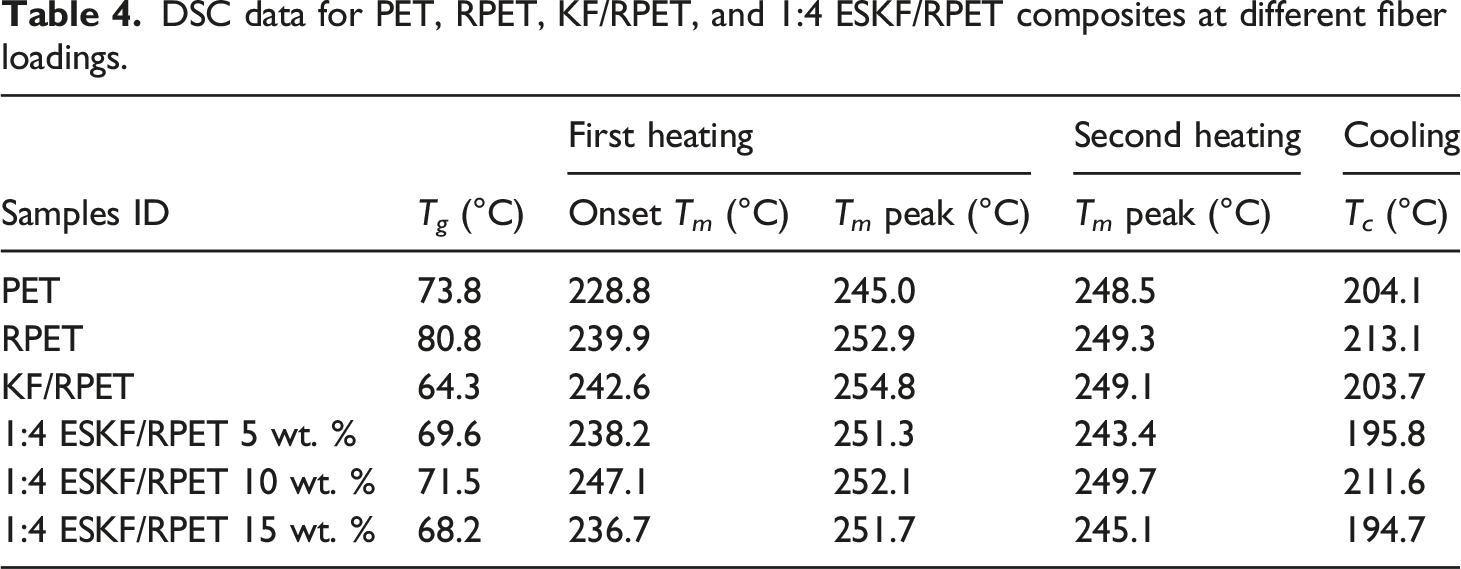
From the DSC results, RPET showed some similarities in comparison to virgin PET having glass transition temperatures (T g ) of 80.8°C and 73.8°C, and melting peaks temperatures (T m ) of 249.3°C and 248.5°C respectively, an indication that the recycling process was efficient, void of contamination and the basis composites were processed at a temperature of 240°C. 20 The extrusion temperature (240°C) has no adverse effect on the thermal phases for RPET and the constituent composites as they have maintained balanced thermal stability values within 240°C.
As seen in Table 4 and Figures 11 and12, observations are that the glass transition temperatures of KF/RPET and ESKF/RPET composites decreased by the addition of fibers. However, the onset melting temperatures of coated composites increased with fiber loading up to 10 wt. % and a decreased at 15 wt. % loading compared to uncoated composites. The 1: 4 ESKF/RPET recorded maximum glass transition, onset, and melting peak temperatures of 71.5°C, 247.1°C, and 249.7°C at 10 wt. % respectively. The DSC results further substantiate the TGA results earlier obtained in Figure 8 and subsequently, in conformity with the composite’s tensile and flexural strength as seen in Figures 13(a) and 13(b) respectively. DSC thermograms of (a) 1:4 ESKF/RPET (b) 1:4 ESKF/RPET composites of 10 wt. % &15 wt. % fiber loadings respectively. Effect of epoxy concentration at different fiber loadings on 

Tensile and Flexural properties
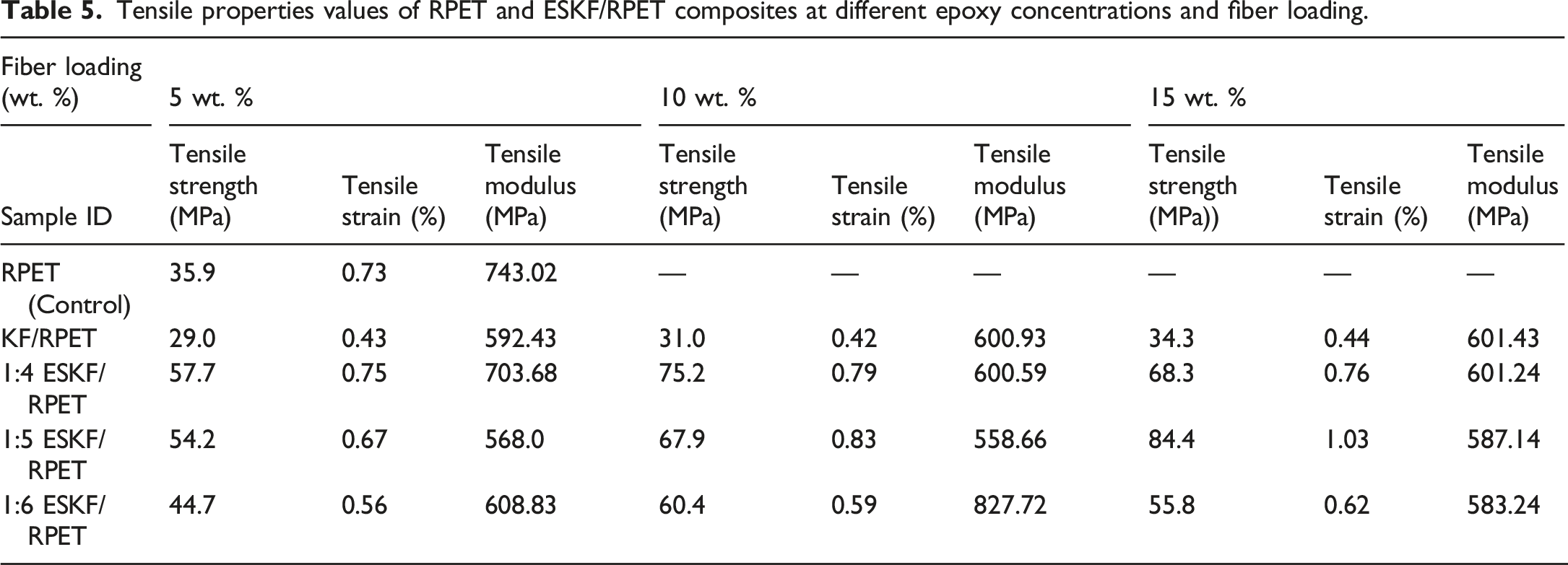
Tensile properties values of RPET and ESKF/RPET composites at different epoxy concentrations and fiber loading.
Flexural properties values of RPET and ESKF/RPET composites at different epoxy concentrations and fiber loading.

From Figure 13(a), the RPET shows a tensile strength of 35.9 MPa which decreased with the incorporation of KF and consequently, the resultant KF/RPET composites showed tensile strength values of 29.0 MPa, 31.0 MPa, and 34.3 MPa at 5 wt. % and 10 wt. % respectively. This implies that the KF/RPET composites suffered some degradation as strength values decreased compared to unreinforced RPET even with increasing fiber loading.
The tensile strength of all epoxy coated-silane treated composites was generally higher than KF/RPET and RPET, and further improved with epoxy coating concentrations and fiber loading. It can be seen that 1:4 ESKF/RPET composites showed the highest tensile strength up to 10 wt. % fiber loading and a drop at 15 wt. %, followed by 1:5 and 1:6. This indicates that the optimum epoxy coating concentration ratio and filler loading for the maximum tensile performance of the composites are 1:4 and 10 wt. % respectively. This might be attributed to the stronger fiber/matrix interfacial adhesion resulting from high viscosity of the epoxy and less amount acetone content of ratio 1:4 leading to the formation of a strong cross-linked network chain between coated-treated ESKF fibers and RPET matrix as compared to 1:6 (with low viscosity) owing to the increased amount of acetone dilution with reduced strength linked network interaction. In other words, 1:4 ESKF/RPET composites have recorded the highest tensile strength compared to 1:5 and 1:6 ESKF/RPET composites. However, Smith et al. 18 reported inferior tensile strength and modulus with epoxy-coated jute fabric reinforced PA6 compared to the uncoated composites with increased concentration.
Figure 13(b) shows the effect of epoxy coating concentrations at different fiber loading on the flexural strength of KF/RPET and ESKF/RPET composites. The values of flexural properties are listed in Table 6. It can be seen that the flexural strength of all epoxy coated-treated fiber ESKF/RPET composites of 1:4, 1:5, and 1:6 coating concentrations generally increased and was better compared to untreated KF/RPET composites. Epoxy coated composites of 1:5 concentration gave the maximum flexural strength of 161.0 MPa at 5 wt. % and further increased with increasing fiber loading of up to 179.0 MPa at 10 wt. % compared to other concentrations. However, a slight drop in strength to 173 MPa at 15 wt. % was observed. The results indicate that the optimum bending property of the composites is at 10 wt.% fiber loading within the low filler loading region. Notably, the 1:5 ESKF/RPET composite displayed the maximum flexural strength at 10 wt. % fiber loading. Hence, the optimum epoxy coating concentration ratio and filler loading for the maximum flexural performance of the composites are 1:5 and 10 wt. % respectively. It is further observed and noteworthy that a higher coating concentration ratio may affect the composites’ flexural properties such as in the case with 1:4 in which the high epoxy: acetone coating concentration of 1:4, limits the diffusion of solution into the fiber substance due to restricted molecular mobility occasioned by the high epoxy coating viscosity. But as the concentration of epoxy coating solution was lowered down (decreased) to 1:5 and 1:6, molecular mobility of the constituents of epoxy coating solution might have increased, and thus, diffusion of epoxy coating solution increased leading to effective fiber coating, increased surface adhesion and stiffening, which reduced the tendency to deformation. Therefore, epoxy coating concentration should be at equilibrium (i.e., not too high or too low viscosity) for optimum flexural properties to be attained hence, ESKF/RPET composites of 1:5 concentration recorded the best flexural properties. Flexural strain and modulus showed the same trends.
Smith et al. 18 also observed increased flexural properties with increasing curative concentration due to the increased stiffness of the fabric after epoxy coating treatment, their flexural strength of neat PA6 and uncoated jute composites were similar, with the coated composites showing lower to higher values with increasing curative concentration. They attributed the low flexural strength of coated jute composites at lower curative content to be due to incomplete curing of the epoxy. However, the flexural strength increased with increasing curing agent concentration which they attributed to high crosslinking of flexible epoxy resulting in improved strength of the fabric and consequently affecting on reinforcement of the matrix.
Impact Properties
Figures 14(a) and (b) show the effect of epoxy coating concentration at different fiber loadings on the impact strength and absorbed energy of uncoated KF/RPET, 1:4 ESKF/RPET, 1:5 ESKF/RPET, and 1:6 ESKF/RPET composites respectively. The values of the impact strength are given in Table 7. In Figure 14(a), the impact strength of RPET increased upon the incorporation of fiber, and coated-treated ESKF/RPET composites show higher impact strength which further improved with increased epoxy coating concentration and fiber loading as compared to KF/RPET composites. From the result obtained, it is observed that 1:4 ESKF/RPET composites were maximum with the highest impact strength at 15 wt.% fiber loading compared to 1:5 and 1:6 ESKF/RPET composites. Effect of epoxy concentrations at different fiber loading on Impact properties values of RPET and ESKF/RPET composites at different epoxy concentrations and fiber loading.

The highest impact strength of 0.0476 KNmm2 was observed with 1:4 ESKF/RPET composite at 15 wt. % fiber loading. ESKF/RPET composites of 1:4 coating concentration gave the highest impact strength of 0.0476 KNmm2 and could be attributed to the high degree of crosslinking of the epoxy resin and higher viscosity compared to 1:5 and 1:6. The impact strength also increased with an increase in fiber loading and maximum impact strength was 15 wt. % fiber loading. Nuthong et al. 19 also reported a decrease in the impact strength of natural fiber reinforced PLA composite increased in fiber content, and concluded that epoxy surface treatment improved the impact property of bamboo fiber/PLA and coconut fiber/PLA composites when compared with the untreated composites.
Absorbed energy also shows a similar trend with impact strength as seen in Figure 14(b). The amount of energy absorbed by the composite samples was determined to ascertain the toughness of the composites. More impact energy is dissipated by debonding of epoxy coated kenaf composites compared to uncoated KF/RPET composite, due to the existence of strong interphase which interrupted the progress of debonding and cracks propagation between the epoxy coated-silane treated fibers/RPET matrix interfaces. Whereas less energy is been dissipated in debonding the uncoated KF/RPET composites due to weak interphase between uncoated fibers and RPET matrix. The impact energy absorbed by 1:4 ESKF/RPET and 1:5 ESKF/RPET composites increase with an increase in fiber loading up to 15 wt. %, but in the case of 1:6 EKF/RPET composite, the absorbed energy increased as the fiber loading increased from 5 wt. % to 10 wt. %, and then decreased as the fiber loading increased up to 15 wt. %. This observation could be attributed to the effect of high fiber density and agglomeration. Overall, when compared to the epoxy coated-treated ESKF/RPET composites, the untreated (KF/RPET) composite showed lower absorbed impact energy which could be attributed to poor interfacial bonding between the untreated kenaf fibers and RPET matrix. Hence, 1:4 ESKF/RPET composites were found to have absorbed more impact energy and followed by 1:5 ESKF/RPET.
Composite morphological Properties
The FESEM micrographs for fracture surfaces of kenaf fiber-filled recycled PET composites of different epoxy concentrations and fiber loadings are presented in Figures 15 and 16 respectively. Fracture surface FESEM micrographs for (a) KF/RPET, (b) 1:4 ESKF/RPET, (c) 1:5 ESKF/RPET and (a) 1:6 ESKF/RPET composites at 500x magnifications respectively. Fracture surface FESEM micrographs for (a) RPET, and 1:4 ESKF/RPET composites for (b) 5 wt. %, (c) 10 wt. % and (d) 15 wt. % fiber loading at 1000x magnifications respectively.

KF/RPET composites in Figure 15(a) revealed evidence of fiber degradation. Fiber debonding surfaces also occurred due to poor interfacial bonding between the untreated kenaf fiber KF and RPET polymer matrix. The KF/RPET composites fracture surfaces also show cracked portion that distinguished the fiber-matrix interface due to weak interfacial interaction between raw kenaf and RPET matrix resulting from fiber degradation at high temperatures
The fracture surfaces morphology of 1:4 ESKF/RPET composites in Figure 15(b) showed a good dispersion of fibers in the RPET matrix with a spot of the ESKF observed to be well embedded in the matrix suggesting good interfacial bonding between the fillers and the matrix. some traces of fibers were seen which indicates that the specimen still retained its structural integrity and with no evidence of fiber degradation due to the surface coating effects with a 1:4 concentration of the epoxy resin. The 1:5 ESKF/RPET composite in Figure 15(c) illustrates the occurrence of ductile failure of the matrix with some fiber breakage. There were an absence of void, holes, and crack portion which indicates good interfacial adhesion between the kenaf fiber and the matrix. The fractured surface morphology of 1:6 ESKF/RPET composites in Figure 15(d) shows evidence of cohesive failure occurrence which indicates good adhesion between the constituents. The specimen also revealed a well-bonded filler and the matrix with few fibers seen suggesting the non-existence of fiber degradation.
In overall, the coated fibers ESKF are visibly seen, well embedded, and bonded with the RPET matrix in the composites system. Hence, all coated-treated 1:4 ESKF/RPET, 1:5 ESKF/RPET, and 1:6 ESKF/RPET composites showed strong fiber/matrix bonding which is responsible for the high mechanical strength of the composites as seen in (Figures 13 and 14). Smith et al. 18 also revealed strong fiber/matrix interfacial bonding for both coated jute fabric composites.
Figure 16(a) shows fracture surfaces of neat RPET without reinforced fibers. The fracture micrographs of 1:4 ESKF/RPET composite specimens for 5 wt. %, 10 wt. % and 15 wt. % fiber loadings in Figures 16(b), (c), and (d) respectively revealed good interactions of coated-treated kenaf fibers ESKF and well embedded in the RPET matrix with no evidence of fiber degradation. The fracture surfaces revealed a cohesive failure of the matrix with some fiber breakage, which could be attributed to the strong interfacial adhesion between the fiber and the matrix for effective stress transfer from the matrix to the fibers due to coating effects in improving the thermal stability and degradation of the fibers. These observations also explained the reasons for the increased tensile, flexural, and impact strength as seen in Figures 13(a), 13(b), and 14 respectively.
ESKF/RPET composite of 10 wt. % fiber loading (Figure 16(c)) revealed more of the fillers visible in the RPET matrix composite system compared to that observed for 5 wt. % loading with fewer fiber contents (Figure 16(b)) which resulted in increased mechanical strength as seen in Figures 13(a), 13(b), and 14 for tensile, flexural, and impact strength respectively. Hence, fiber loading has significant effects on the morphological characteristics of coated-treated composites. Chun et al. 27 reported an increased surface contact area with decreased interfacial adhesion between the fillers and the matrix due to a high weight fraction of 70 wt. % and concluded that if a coupling agent is to be incorporated, then alkali treatment of fiber is unnecessary for use in high filler loading composites to improve the interfacial adhesion between polymer resin and the fiber.
Conclusions
The effect of different concentrations of epoxy coating treatment on thermo-mechanical properties of kenaf fiber– recycled poly(ethylene terephthalate) composites have been investigated. It can be concluded that: • FTIR spectroscopy has demonstrated that treatment of kenaf fibers with silane and epoxy coating treatment modified the chemical structure and improved their interfacial bonding property. • The thermal and mechanical properties of epoxy-coated silane-treated kenaf fibers-recycled PET (ESKF/RPET) composites were influenced by the concentration of the epoxy coating treatment and fiber loading. These properties were optimum in epoxy coating solution obtained from a 1:4 (epoxy: acetone) ratio. Thus, 1:4 epoxy concentration is found to be more thermally stable, followed by 1:5 and 1:6, with maximum fiber loading of 10 wt.% for thermal properties, tensile and flexural strength, and a maximum of 15 wt. % for impact properties. • SEM results of epoxy coated-silane treated kenaf fibers ESKF revealed improved surfaces and further facilitated the effective interactions with RPET matrix as compared to the untreated kenaf KF. The fracture surface morphology of coated-treated ESKF/RPET composites showed a strong fiber/matrix adhesion, the untreated KF/RPET composites revealed poor interfacial bonding found between the RPET matrix and the kenaf fiber reinforcement with clear evidence of fiber degradation resulting in low mechanical properties as compared to the coated-treated composites. • The current research findings are original and valid for improving the thermal degradation resistance and stability of natural fibers and the mechanical properties of engineering thermoplastic composites. It is believed that epoxy coated – silane-treated textile kenaf fibers reinforced recycled PET composites have the potentials to be utilized in high-temperature industrial and engineering applications.
Footnotes
Acknowledgements
The authors gratefully acknowledged the School of Materials and Mineral Resources Engineering, Universiti Sains Malaysia USM, Malaysia and the Centre of Polymer Composite Research and Technology, Institute of Science, Universiti Teknologi MARA, UiTM, Selangor, Malaysia, and the Department of Polymer and Textile Engineering, Faculty of Engineering, Ahmadu Bello University Zaria, Nigeria, for their collaborative research support and the use of their manufacturing and testing facilities.
Declaration of conflicting interests
The author(s) declared no potential conflicts of interest with respect to the research, authorship, and/or publication of this article.
Funding
The author(s) received no financial support for the research, authorship, and/or publication of this article.