
Abstract
Planar frequency selective surface (FSS) fabrics with grids, strips or patches by simple methods of patching, embroidery, clipping and carving were fabricated. The periodic structures, laminated structures, processing method and materials pertaining to the electromagnetic shielding behaviors were investigated. Firstly, equivalent circuit and electromagnetic (EM) shielding behavior of basic frequency selective structure units and complex fretwork structure were provided, involving the decoupling of complex fretwork structure. In addition, various laminating structures of SPs and SGs were determined, one of superposition of SPs and SGs provides a SE peak of 40.2 dB (average SE of 25.1 dB in the whole frequency domain), the other presents a SE peak of 27.1 dB (average SE of 19.1 dB in the whole frequency regime). Furthermore, tunable selective electromagnetic shielding by a simple mechanical way was provided, which can realize a tunable SE peak varying from 730 MHz to 1580 MHz. This work might provide a perspective for the assemble and analytical approximation of FSS fabrics for scientists and engineers in this cross-disciplinary field.
Keywords
Introduction
Nowadays, electromagnetic interference (EMI) generated by electronic products will cause electrical interference with the operation of equipment and make impacts on human health.1–3 Many works have reported frequency selective surface (FSS) used as radome, metamaterial absorber and microwave blocker. 4 Electromagnetic shielding means electromagnetic waves were blocked in the whole range of frequency. And frequency selective electromagnetic shielding is attenuating the unwanted electromagnetic radiation in a particular frequency emitted from various electrical and electronic devices. FSS is made of periodic patterns, which is firstly found in the early 1900s, and in the 1960s FSS was used in radar and stealth applications. 5 Periodic patterns can be composed of metal patches or metal substrate with holes, and they can shield EM energy through the intrinsic resonating determined by the size of periodic patterns.4,5 The individual units with a certain arrangement in periodic patterns will form a new structural unit, which determines the electromagnetic shielding behavior. In order to better analyze periodic structure, the structure of FSS can be decoupled by an equivalent circuit where L and C are dependent on the sample geometries. 6 Gouri et al. 7 presented a miniaturized stop-band FSS of interconnected square ring with angular stability. Tianwu Li 8 and D. Kanchana 9 got a good angular stability with strong-coupled FSS where the bottom layer with Jerusalem-shaped and the top layer with cross-shaped respectively. Irfan et al. 10 has designed a FSS structure of top surface with cross dipole and bottom surface with ring which are stable to TE and TM polarizations.
The most common electromagnetic shielding materials include metal, conductive polymers and carbon materials, which are usually non-soft or non-flexible materials, 11 involving the fabrication methods of metal depositing, coatings, embedding conductive sheets and photoetching.12–15 Most FSS are using metal substrate owing to metal is the most conventional conductive materials. 16 However, the rigidness, uneasiness and high weight of metal limits its application for people wearing.
Obviously, textiles are soft materials with low bending rigidity and softness. Frequency selective fabrics (FSFs) are a soft fabric with periodic patterns which can possess the function of frequency selective shielding. Clipping and carving fabric is a type of woven fabric, which can easily form FSFs through cutting off the floating thread and the cooperation between different tissues of conductive yarn and nonconductive yarn. Embroidered fabric can be easily performed by embroidering conductive yarns in textile. Silver yarns and stainless yarns are conductive yarns which are softness and can give better electromagnetic SE.17–18 Herein, two yarns (silver-plated yarns and stainless yarns) with flexible property are embroidered in cotton and polyester blended yarn fabrics so that softness and wearable fabrics can be acquired. Besides, polyester possesses good strength characteristic and cotton exists better moisture absorption, both are dielectric like air in terms of microwave, so that polyester cotton blend fabric is selected as dielectric fiber.
Variable frequency selection characteristic can be acquired by tensile of elastic fabric. 19 That is a different way from PIN diodes method, 20 in which the shift of frequency bands can realized by controlling the bias voltage of the feed network of PIN diodes. Therefore, it is meaningful to construct FSS by using woven technology. Besides, complex pattern fitted by basic units and the effect of lamination direction of FSS on the SE were rarely reported. The electromagnetic shielding behaviors with emphasis on different structure, lamination direction and tunable selective frequency are of concern. Here, we are exploring in textile structure, and the knit fabric is selected ascribed to its conformability and operability. It is worth noting that inorganic nonmental fiber such as Glass, Quartz and the patching, embroidery, carving and clipping on them still be quite a challenge and deserved attention.
Therefore, soft FSFs were performed through embroidery and clipping-carving technology, involving the use of nylon silver-plated yarns and stainless-steel yarns being embedded into the soft fabric to form periodic pattern. The electromagnetic shielding behaviors of fabric pattern structure are determined. The copper-nickel patches by surface mount technology (tradition rigid plate) and hand embroidery fabrics (soft FSFs) were provided and compared. In addition, the characteristic of frequency selective fabrics (FSFs) with different periodic patterns were given in this paper. Moreover, the effect of lamination structures on electromagnetic shielding behaviors and switchable frequency bands acquired by mechanical stretch were carried out.
Experimental
Materials
Silver-plated polyamide yarn is from Shengxin Teshu Shengdai CO.LTD, in Guangzhou. The denier of silver-plated polyamide yarn is 251 D and the weight of the yarn is 78.12 g/2800 m under commercial moisture regain (9.89%)
Sample preparation
The structure parameters of samples are listed in Table 2. Samples #1 to #14 are in use of Cu and Ni patch pasted on the cotton and polyester blended yarn fabric by tailoring the Cu and Ni patches into strips based on the designed proportion. Samples #15 and #16 are prepared by hand embroidery method, involving the use of nylon silver-plated yarns and stainless-steel yarns embroidered on the cotton and polyester blended yarn fabrics to form fretwork patterns. The hand embroidery uses the flat embroidery method which thread starts from one side of the outline of the pattern and continues to the other side of the outline. Patterns are embroidered on both sides of the fabric. Samples #17 to #20 are different superposition of #3 and #11 samples. Sample #24 and #25 samples are superpositions of #3 and #11 at different positions. Sample #21is prepared by sticking Cu and Ni patch to weft-knit polyester (PET) fabric, sample #22 and #23 are refer to the tension of sample #21.
Characterization
The instrument for measuring of EMI shielding effectiveness characterization is FY800 Fabric EM Shielding Properties Tester (Wenzhou Fangyuan Instrument CO.LTD). The schematic diagram of instrument is shown in Figure 1. Schematic diagram of test equipment for EMI shielding effectiveness characterization of insertion loss method. Dimensions of the specimen for EMI shielding effectiveness characterization are suspended. The inner and outer dimensions of the ring specimen are 16.5 mm and 38.0 mm respectively.
Shielding efficiency of tested samples shall be calculated according to formula18,21 as

As shown in Figure 1, the EMI shielding effectiveness is measured by a FY800 Fabric EM Shielding Properties Tester using the coaxial cable method. Due to its dimension, theoretically allows testing at frequencies up to 3.5 GHz. The cut-off frequency is given by follows

The electromagnetic shielding mechanism is shown in Figure 2. Pi represents input power, Pr means power reflected, Pt is power transmitted. The shielding effectives can be expressed. Mechanism diagram of electromagnetic shielding for embroidery fabric. Pi represents input power, Pr refers to power reflected, Pt is power transmitted.

Figure 2 depicts electromagnetic shielding mechanism. when plane waves arrive in the surface, the fabric exhibits the ability to minimize the electromagnetic waves through reflecting plane waves.
22
In addition, electromagnetic waves can be absorbed owing to induced current. At last, the residual electromagnetic waves will penetrate the fabric. Absorption and reflection of electromagnetic waves can be calculated as


Where SEA is absorption loss, SER represents reflection loss. R refers to the power coefficient, A refers to absorptivity, and T is transmissivity. The incident fields are plane wave in the transverse electromagnetic (TEM) propagation mode in order to simulate a far-field EM wave source (a source at the distance d > λ/2 π). A TEM propagation mode ensures that there is neither electric field nor magnetic field along the propagation direction of the EM wave and both fields are transverse to the propagation direction. 23
Results and discussion
Electromagnetic shielding behaviors of competitive materials with frequency selective properties
Electromagnetic shielding behaviors of competitive materials with FS properties.
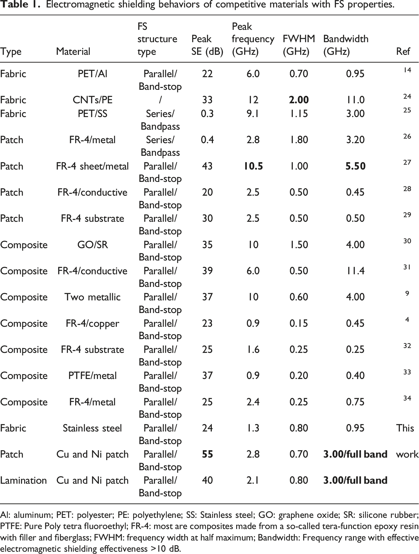
Al: aluminum; PET: polyester; PE: polyethylene; SS: Stainless steel; GO: graphene oxide; SR: silicone rubber; PTFE: Pure Poly tetra fluoroethyl; FR-4: most are composites made from a so-called tera-function epoxy resin with filler and fiberglass; FWHM: frequency width at half maximum; Bandwidth: Frequency range with effective electromagnetic shielding effectiveness >10 dB.
The structure parameters and EM shielding results of all samples.

W: D: it refers to the ratio of width (W) of conductive phase to dimension (D) of non-conductive phase, the unit is centimeter (cm); FWHM: frequency width at half maximum; Bandwidth: Frequency range with effective electromagnetic shielding effectiveness >10 dB.

The maximum SE, peak frequency and average SE of samples #1–#26. Green pentacle represents the maximum SE in the 30–3000 MHz, red ball refers to peak frequency and blue bar chart stands for the average value of SE from 30 to 3000 MHz.
Equivalent circuit and EM shielding behavior of basic frequency selective structure unit
Structure unit plays a great important role in frequency selection characteristics of electromagnetic shielding. Figure 4 shows the diagram of equivalent circuit and the electromagnetic shielding effectiveness of different periodic structures cell, including square, strip and square grids made of Cu and Ni patch. Figure 4(a), (d) and (g) show SPs, Ss and SGs shape respectively. When plane waves are incident into periodic structure fabric, it will excite a certain number of plane waves of floquet harmonics
35
to shield electromagnetic waves. Diagram of fabric structure, equivalent circuit and the electromagnetic shielding effectiveness under different cell periodic structures of square, strip and square grids by using Cu and Ni patch. (a) Cu and Ni SPs. (d) Cu and Ni Ss patch. (g) Cu and Ni SGs patch. (b), (e) and (h) are the equivalent circuits correspond to the cell periodic structures of (a) square, (d) square, strip and (g) square grids respectively. And (c), (f) and (i) are the corresponding results of electromagnetic shielding effectiveness for (a) square, (d) strip and (g) square grids with different size parameters of W: D respectively. W: D refers to the ratio of width (W) of conductive phase to dimension (D) of non-conductive phase, the unit is centimeter (cm). The values of W: D for samples #1-#11 refer to Table 2, meanwhile, which are masked in corresponding figures.
The equivalent circuits correspond to the cell periodic structures of SPs (Figure 4(a)), Ss (Figure 4(d)) and SGs (Figure 4(g)) are presented in Figure 4 (b), (e) and (h) respectively. There are two kinds of equivalent circuit types of L and C in series (Figure 4(b) and (h)) and L and C in parallel (Figure 4(e)). Meanwhile, the results of electromagnetic SE for different size parameters of W:D were provided in Figure 4(c), (f) and (i). In addition, Figure 4(c) and (f) pay attention to influence of structure cell size on selective electromagnetic shielding by keeping Cu and Ni patch composition constant but altering structure size.
Figure 4(c) exhibits the electromagnetic SE of square fabrics #1-#4 in which W:D are 1:0.5, 1.5:0.75, 1.5:0.5 and 2:1 (cm) respectively. The SE of fabric #1 can be basically ignored, indicating outstanding transmittance for microwave in the band of 0.03–3 GHz. It should be noted that the amount of conductive patch of fabric #1 is same to that of fabrics #2 and #4. However, fabrics #2 and #4 give superior peak SE values of 11.66 dB at 2530 MHz and 18.03 dB at 2330 MHz respectively. Fabric #3 gets maximum SE of 14.41 dB at 1680 MHz, and the amount of conductive patch of #3 is not same to #1, #2 and #4. Besides, SE of fabrics #2, #3 and #4 in other frequency bandwidth are less than 10 dB which does not present effective electromagnetic shielding. Consequently, as displayed in Figure 4(c), the SPs structure with L and C in series is dominated by transmission in the low frequency regime of 0.03–3 GHz. This band pass phenomenon of SPs structure is attributed to that most of incident waves pass through without forming induced current when the electromagnetic wave is not at the given resonant frequency of SPs.
Figure 4(f) shows electromagnetic SE results of strip patches with three different ratios of W:D. The W:D of fabric #5 is 0.5:0.25 (cm), and fabric #5 gives a corresponding SE peak of 36.2 dB at 1480 MHz. The W:D of fabric #6 is 1:0.5 (cm) and its peak value of SE is 33.7 dB at 1280 MHz. The W:D of fabric #7 is 2:1 (cm) and a corresponding SE peak value of 36.2 dB at 730 MHz is provided. It can be observed that SE peak is determined by the width of Cu and Ni patch, in which the wider the Cu&Ni patch, the smaller the frequency of SE peak. This is contributed to the L and C differences comes from the various patch width. Meanwhile, SE results of fabrics #5, #6 and #7 are greater than 10 dB in most frequency regime, and the maximum SE is more than 35 dB. In addition, the comparison of Figure 4(c) and (f) indicates strips (Ss) structure with L and C in parallel provides a greater shielding electromagnetic effectiveness than SPs structure.
Figure 4(i) is the corresponding results of electromagnetic shielding effectiveness for SGs with different W: D of 0.5:1 (#8), 0.5:0.5 (#9), 1:0.5 (#10) and 0.5:1.5 (#11). It can be observed that the electromagnetic SE is above 10 dB over the full band and gives an obvious SE peak. The SE peak value of fabric #8 reaches 33.9 dB at 2480 MHz, the SE peak value of fabric #9 is 44.6 dB at 2030 MHz, the SE peak value of fabric #10 is up to 63.2 dB at the frequency of 1730 MHz, and the SE peak value of fabric #11 comes up to 36.9 dB at 2080 MHz. Obviously, samples #9 and #10 exhibit a greater SE than that of samples #8 and #11. This is attributed to the content of Cu and Ni patch of samples #9 and #10 is more than #8 and #11 samples. At the same time, the large distance of conductive band will lead to small capacitance value, which weakens the resonating attenuation.
In brief, Figure 4 proves that structure with C and L in parallel gives a better electromagnetic SE in low frequency regime, and different ratio of W:D and conductive material content can make a significant influence on the frequency selective peak position of electromagnetic shielding.
EM shielding behavior of fretwork structure
To explore the connections between complex structures and basic units, we prepared a fretwork structure of Cu and Ni patch (#12) as shown in Figure 5(a). And this fretwork structure can be decoupled into cell periodic structures of SGs or SPs. The equivalent circuit of fabric #12 is presented in Figure 5(d). It can be easily observed that equivalent circuit of #12 is dominated by L and C in parallel. (a) Structure diagram of fabric with Cu and Ni fretwork patch #12 which is decoupled into two types of cell periodic structures of square grids (SGs) and square patches (SPs). (b) The electromagnetic shielding effectiveness peak of patch fretwork #12 is fitting by two types of cell periodic structures of SGs #13 and #14 (refer to (c)). (c) Diagram of fabric structure of fretwork patch, SGs #13 and SGs #14. The Sizes of (W, D) for #12, #13 and #14 are (0.5:0.25), (1.8:0.9) and (0.5:1.5). The unit is centimeter (cm). (d) Equivalent circuit of #12 fretwork patch based on the decoupling of fretwork structure (refers to Figure 5. (a)).
As displayed in Figure 5(b), the fretwork #12 gives two obvious SE peaks of 24.8 dB at 980 MHz and 22.3 dB at 1980 MHz, and both provide a SE greater than 10 dB over 2.25 GHz bandwidth, which is different from the SE result of SPs structure (Figure 5(a)). Fretwork patch #12 can be approximatively fitted by two periodic structure cells of SGs #13 and #14 shown in Figure 5(c). The electromagnetic shielding effectiveness results of #12, #13 and #14 are displayed Figure 5(b). The SE peak value of sample #13 (W:D is 1.8:0.9) is 54.5 dB at 1230 MHz, and the SE peak value of sample #14 (W:D is 0.5:1.5) is 36.9 dB at 2080 MHz. Apparently, the two peaks of sample #12 can be approximatively corresponded to the peaks of samples #13 and #14 respectively. Consequently, Figure 5(b) results prove that the electromagnetic equivalent structure of fretwork structure is more like that of SGs structure, and complex structure can be decoupled into basic structure units which possess the same equivalent circuit.
Fretwork structure with different materials
As Figure 6 shown, the electromagnetic shielding of Cu and Ni fretwork patch #12 gives an average SE value of 14.3 dB. However, the texture of Cu and Ni fretwork patch is stiff compared with soft textile, so that the comfort of Cu and Ni patch to wearability of fabric is limited. To solve this problem, we adopt two kinds of yarns, silver-plated yarn and stainless-steel yarn, to fabricate sliver-plated fretwork #15 and stainless-steel fretwork #16 by using hand embroidery method. The results of fretwork fabrics with different materials are shown in Figure 6(d). It is conspicuous that variations of material and technology cause remarkable influence on the results of electromagnetic SE. The electromagnetic SE of patch fretwork #12 gives two obvious SE peaks of 24.8 dB at 980 MHz and 22.3 dB at 1980 MHz. Silver-plated fabric #15 provides an average electromagnetic effectiveness of 9.6 dB and doesn’t provide obviously peak exclude high SE in this low frequency. Interestingly, stainless steel fretwork #16 presents an obvious SE peak (24.1 dB) at 1330 MHz. What is noteworthy is that #12 and #16 fretwork fabrics provided similar SE peak value around 25 dB, which is ascribed to their same fretwork structure and size. The reasons why fabric #15 doesn’t give an obvious peak can be mainly attributed to the conductivity resulting from the diversity of multilevel structure of a yarn fabric, as well as the conductivity of polyamide silver-plated fiber is 5.1×10⁵ S·m−1 and the conductivity of stainless-steel fiber is 2.2 × 10⁸ S·m−1. In addition, stainless steel yarns are continuous filaments, while silver-plated nylon yarns of fabric #15 are discontinuous fibers. Thus, the stainless-steel yarn corresponds to the continuous solid conducting phase, and the silver coated yarn corresponds to the hollow conducting phase (the conducting silver material is loaded on the surface). This structural difference between stainless steel yarns and silver-plated yarns will produce discrepancies of electrical conductivity, dielectric behavior, and electromagnetic shielding behavior. To sum up, Figure 6 exhibits a simple method to assemble electromagnetic shielding soft fabric by embroidery weaving of conductive yarns, which possesses the characteristic of selective electromagnetic shielding and can be widely used to wearable devices. The schematic diagrams and electromagnetic shielding effectiveness of fretwork fabric with different materials. (a) The diagrams of fretwork fabric #12 which is Cu and Ni patch. (b) The diagrams of fretwork fabric #15 which is made of silver-plated yarns. (c) The diagrams of fretwork fabric #16 which is stainless steel yarns. (d) The electromagnetic shielding effectiveness of sample #12, #15 and #16.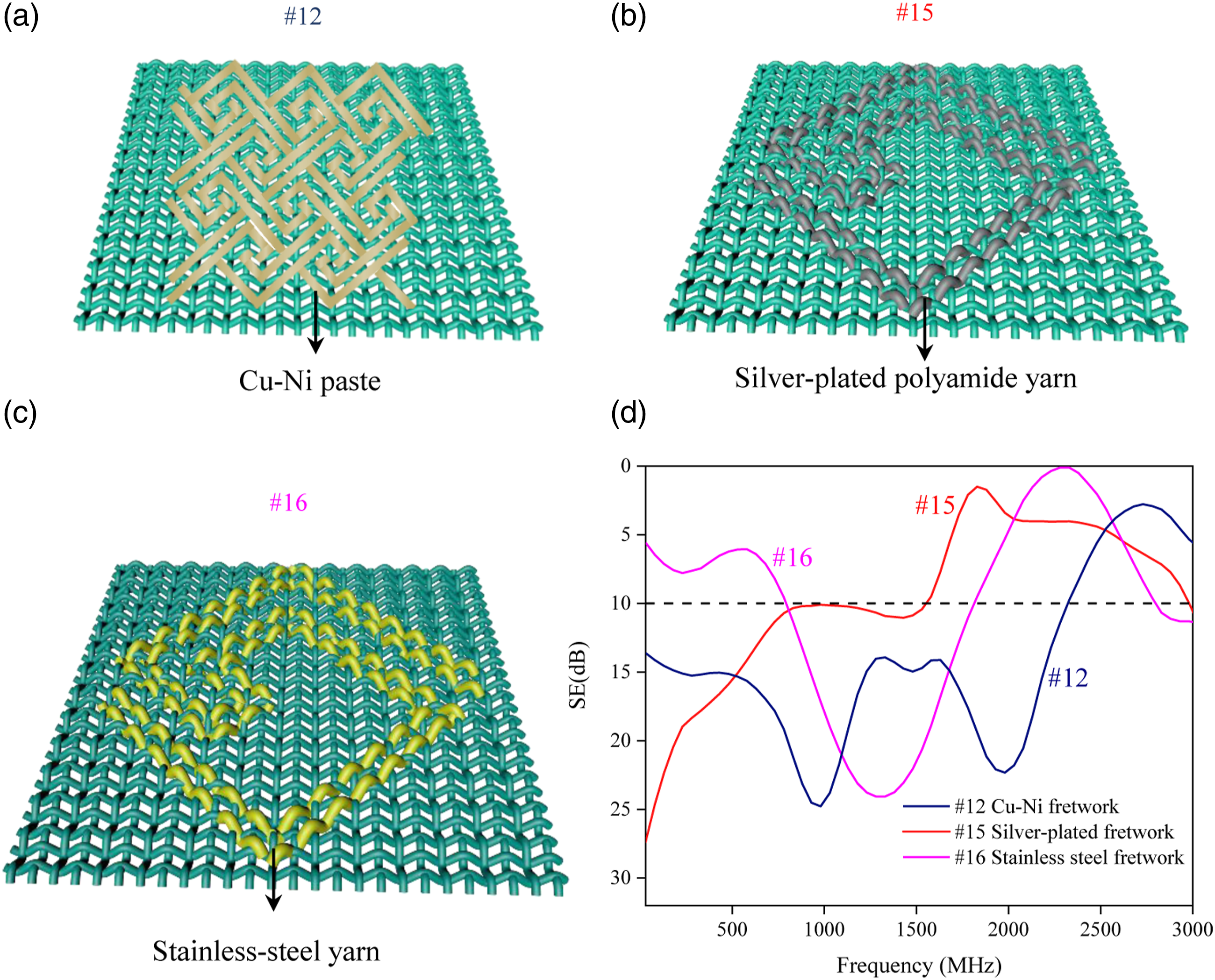
Woven fabric
Embroidery technology (Figure 6) is a well method to produce periodic patterns, however, the efficiency is slower than woven technology. Therefore, this part adopts woven technology to carry out selective electromagnetic shielding as the woven process is easy for mass production. Figure 7(a) shows the diagram of clipping and carving fabric. The yellow part represents conductive stainless-steel yarns, the light blue refers to non-conductive polyester cotton yarns and the green represents polyester yarns. Figure 7(b)-(d) are the diagram of honeycomb weave, openwork weave and waved pique weave structure, respectively. The weft (gray part) refers to conductive stainless-steel yarns, the warp (blue part) means non-conductive polyester yarns. Figure 7(e), (f) show the electromagnetic shielding effectiveness of clipping and carving fabrics of SG and Ss structure. The average SE values of fabrics of SG (W:D = 4:1), SG (W:D = 4:2.5) and Ss (W:D = 1:0.5) are 43.9 dB, 36.5 dB and 27.8 dB respectively. It can be observed that the SE peak value of fabrics of SG (W:D = 4:1) reaches 66.9 dB at 1430 MHz. The SE peak value of fabrics of SG W:D (4:2.5) reaches up to 51.3 dB at 1480 MHz and the peak value SE of Ss W:D (1:0.5) is 36.9 dB at 1330 MHz. Figure 7(f) displays the electromagnetic shielding effectiveness of clipping and carving fabrics of Ss structure with different ratio of W:D. Apparently, the SE value varies with the change of the ratio of W:D. The average SE values of fabrics of Ss with W:D of 2.5:0.5, 5:1 and 6:1.5 are 25.2 dB, 32.6 dB and 42.6 dB respectively. The SE peak value of Ss (W:D = 2.5:0.5) reaches 57.2 dB at 1580 MHz, the SE peak value of fabrics of Ss (W:D = 5:1) reaches 55.4 dB at 1380 MHz and the SE peak value of fabrics of Ss (W:D = 6:1.5) reaches 35.1 dB at 1380 MHz. Figure 7(g) shows the electromagnetic shielding effectiveness of honeycomb weave, openwork weave and waved pique weave structure. Honeycomb weave, openwork weave and waved pique weave give SE peak values and the average SE values of 19.1 dB, 18.5 dB and 28.8 dB in the frequency regime of 0.03–3 GHz respectively. Obviously, woven fabric with varies structure exhibit selective electromagnetic shielding effectiveness that average SE values obtained more than 10 dB. This is attributed to the different weave structure which cause the various tightness of the weft and the gaps between yarns. As shown in Figure 7(h) the value of SE/Grammage and SE/Thickness of waved pique weave are higher than the other structures of honeycomb weave and openwork weave, in which the content of conductive yarns of waved pique weave is lower than the others at the same square meter weight. However, waved pique weave obtains the better SE value than the other structure fabrics. Consequently, fabric structures can result in different electromagnetic shielding effectiveness. The electromagnetic shielding effectiveness of clipping and carving fabrics with different structures. (a) The diagrams of clipping and carving fabric. And which is suspend to the left bottom of (e) and (f). (a)The yellow color refers to conductive area involving stainless-stell yarns, the green part refers to nonconductive area involving polyester cotton yarns and polyester yarns. (b), (c) and (d) are the diagram of honeycomb weave, openwork weave and waved pique weave structure, respectively. (e) The electromagnetic shielding effectiveness of clipping and carving fabrics of SG structure with W:D of 4:1, 4:2.5 and 1:0.5. (f) The electromagnetic shielding effectiveness of clipping and carving fabrics of Ss structure with W:D of 2.5:0.5, 5:1 and 6:1.5. (g) The electromagnetic shielding effectiveness of honeycomb weave, openwork weave and waved pique weave structure. (h) Radar images of SE average value for honeycomb weave, openwork weave and waved pique weave structure in terms of thickness and grammage.
To sum up, woven process with conductive yarns is a well method to mass produce FSFs with high electromagnetic shielding performance, which is rarely reported.
Laminated structure
Figure 8 shows the electromagnetic shielding behaviors of different superpositions of fabrics #3 (SPs) and #11 (SGs). The W/D of #3 and #11 are 1.5 cm/0.5 cm and 0.5 cm/1.5 cm respectively (Figure 8(a)). All the samples of #17 to #20 are placed in a complementary form. #17 is the outward superposition of SPs and SGs. #18 is the inward superposition of SPs and SGs. #20 is the superposition of SPs inward and SGs outward. The electromagnetic SE results of #17, #18, #19 and #20 are displayed in Figure 8(b). Fabric #17, #18, #19 and #20 give SE peak values of 34.8 dB at 1530 MHz, 29.4 dB at 1580 MHz, 27.1 dB at 1730 MHz, and 40.2 dB at 2080 MHz, including average SE values of 26.6 dB, 20.1 dB, 18.9 dB and 25.3 dB in the frequency regime of 0.03–3 GHz respectively. Apparently, the difference of laminating structure makes a distinct impart on selective electromagnetic SE. Take #17 and #18 as an example, #17 is outward superposition so that gap between conductive surfaces is greater. While SPs and SGs of #18 are overlapped and the distance between conductive surfaces is nearly to zero due to the inward superposition. The above different laminations result in the diversity of impedance (Z), and Z= R+ j (ωL −1/(ωC)). Where R is the resistance, ωL is the inductive reactance, and 1/(ωC) is the capacitive reactance. The resistance, inductive reactance, and capacitive reactance are greatly influenced by above laminated structure. For #17, the space between SPs and SGs can generate a capacitance so that SE of #17 is greater than that of #18. As presented in Figure 8, although #19 and #20 possess the same distance, the SE of #19 (average SE of 18.9 dB) and #20 (average SE of 25.3 dB) are significantly different. Which is mainly due to first contact surface of plane wave. For #20, plane wave is firstly hitting to Cu and Ni patch with a lower impedance match and that is benefit to form induced current resulting in more reflection attenuation, so that #20 gives a higher SE value. Overall, Figure 8 shows lamination direction influence on electromagnetic shielding effectiveness. These composite fabrics can produce different electromagnetic shielding effectiveness by varying lamination direction and be used as tent, costume, etc. The electromagnetic shielding effectiveness for different superposition of two types of Cu and Ni patch fabrics of #3 (SPs) and #11 (SGs) which are structurally complementary (The W/D of #3 and #11 are 1.5 cm/0.5 cm and 0.5 cm/1.5 cm respectively.). (a) The diagrams of 4 different superposition structures. #17 is the outward superposition of #3 and #11, the order between the layers is +--+. As masked in the suspend part of the figure, “+” means the conductive Cu and Ni patch, “-” means non-conductive support fabric. #18 is the inward superposition of #3 and #11 with the is layers order of -++-, #19 is the superposition of #3 outward and #11 inward under layers order of -+-+ and #20 is the superposition of #3 inward and #11 outward under layers order of +-+-. All samples are placed in a complementary form. (b) The electromagnetic shielding effectiveness of different superposition states.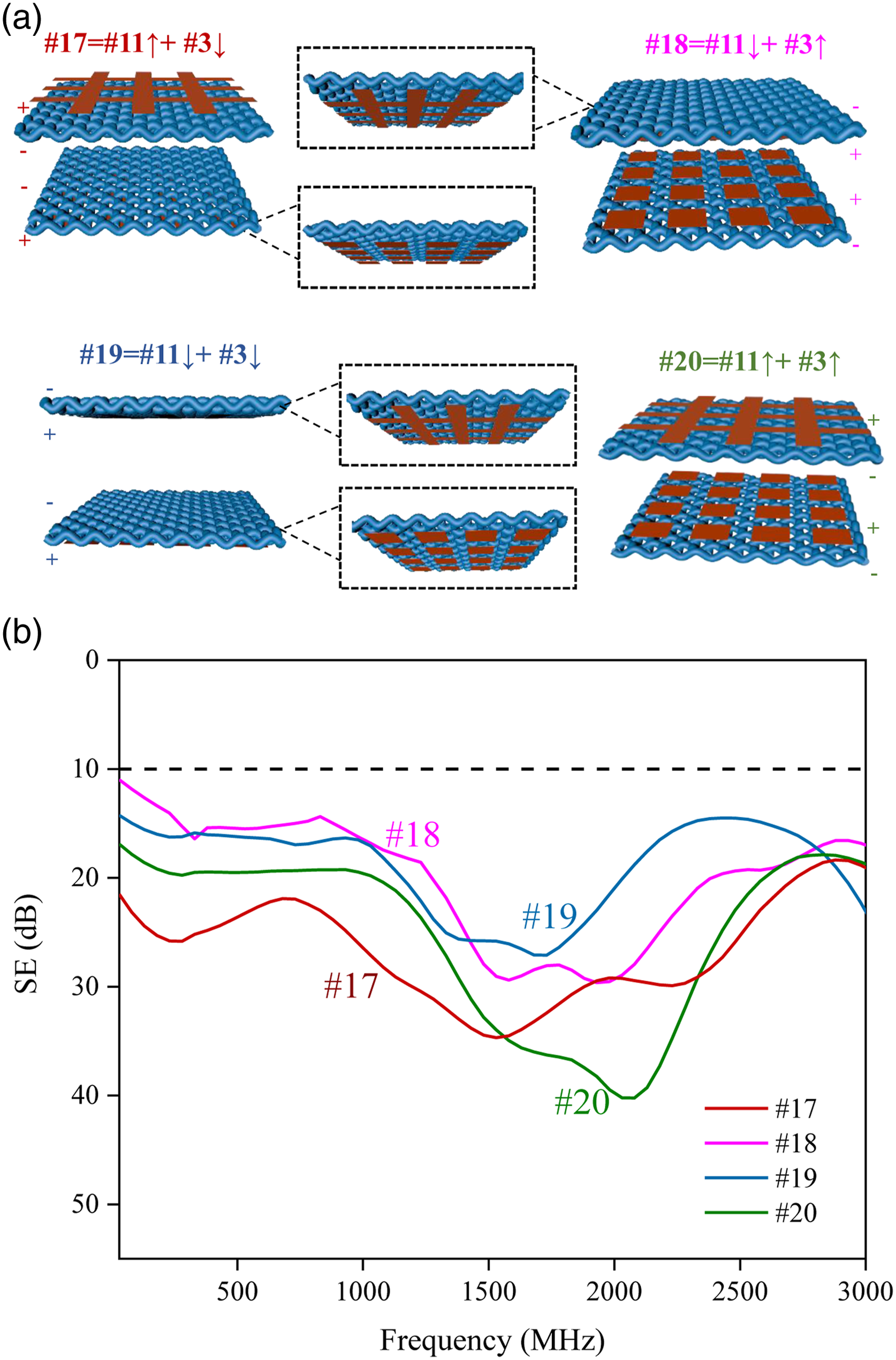
Tunable frequency selective electromagnetic shielding
Figure 9 presents a way to achieve tunable selective electromagnetic shielding characteristic. Fabric #21 is in the form of Cu and Ni patch sticked into elastic fabric as shown in Figure 9(a). The ratio of W:D can be adjusted by stretching of elastic fabric. Figure 9(a) shows one sample under three different tension states with W:D of 1.5 : 0.5 (#21), 1.5 : 1 (#22), 1.5 : 1.5 (#23) respectively. And the electromagnetic SE of fabrics #21, #22, and #23 are shown in Figure 9(c). Fabric #21 gives a SE. Peak value of 43.4 dB at the frequency of 1580 MHz and an average SE value of 17.0 dB in the frequency regime of 0.03–3 GHz. #22 fabric provides a peak SE of 32.1 dB at the frequency of 1080 MHz and an average SE value of 16.1 dB in the frequency regime of 0.03–3 GHz. #23 fabric shows a peak SE of 36.77 dB at the frequency of 730 MHz and an average SE value of 16.7 dB in the frequency regime of 0.03–3 GHz. The SE peak frequencies of #21, #22, and #23 decrease from 1580 MHz to 1080 MHz and 730 MHz with the W:D vary from 1.5:0.5, to 1.5:1 and 1.5:1.5. To sum up, the SE peak frequency of #21- #23 fabrics goes down when elastic fabric is stretched, this suggests that SE peak frequency can be controlled by stretching. Dynamic tunable selective electromagnetic shielding. (a) The diagram of three different states of #21, #22 and #23 with W:D of 1.5:0.5, 1.5:1, 1.5:1.5 respectively when elastic fabric with Cu and Ni strips is pulled. (b) The diagram of #3 inward and #11 (Cu and Ni patch) outward superposition in different positions, the W:D of SGs and SPs is 0.5:1.5 and 1.5:0.5 respectively. #24 is the edge overlap of #3 and #11, #25 is the middle superposition of #3 and #11. (c) The electromagnetic shielding effectiveness of three ratios of W:D when elastic fabric is pulled. (d) The electromagnetic shielding effectiveness of four different states. #20 is superposition of #3 inward and #11 outward. #26 is the whole Cu and Ni patch fabric.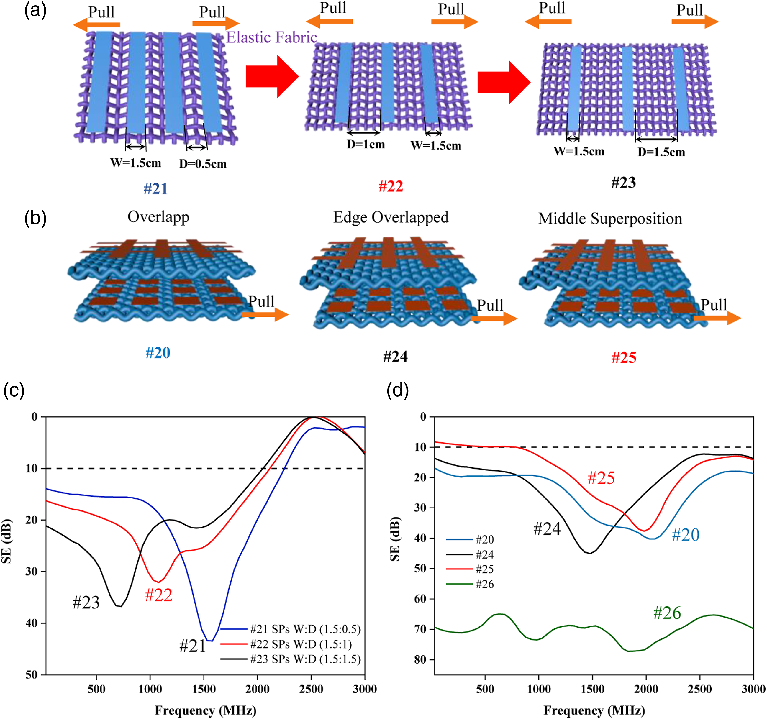
At the same time, Figure 9(b) shows the influence of relative displacement of structure cells on electromagnetic shielding behaviors. The structure cells of #3 (SPs) and #11 (SGs) are same as that of Figure 8, the W:D of SGs and SPs is 0.5:1.5 and 1.5:0.5 respectively. Tunable selective electromagnetic shielding can be achieved based on the mobile superposition position of #3 and #11. Fabric #20 is superposition of #3 inward and #11 outward. Fabric #24 is the edge overlap of #3 inward and #11 outward rather than complementary in shape of fabric #17 in Figure 8. Fabric #25 is the middle superposition of #3 inward and #11 outward. And sample#26 is the fabric with Cu and Ni patch covering the entire surface. Figure 9(d) shows the electromagnetic shielding effectiveness of fabric #20, #24, #25 and #26. Obviously, fabric #20, #24 and #25 all give a SE peak. Fabric #20 gives a SE peak value of 40.2 dB at the frequency of 2080 MHz and an average SE value of 25.3 dB in the whole frequency. Fabric #24 gives a SE peak value of 45.1 dB at the frequency of 1480 MHz and an average SE value of 22.6 dB in the whole frequency. #25 fabric gives a SE peak of 37.7 dB at the frequency of 1980 MHz and an average SE value of 18.1 dB in the whole frequency. Fabric #26 doesn’t not possess an obviously peak SE and gives an average SE value is 70.1 dB in the whole frequency. These results indicates that relative locations of cell structures have some influence on selective electromagnetic shielding. However, this influence is limited. The selective frequency varies about 0.6 GHz by changing cell structure position. The tunable selective electromagnetic of Figure 9(c) and (d) is owing to the extension, mutual displacement, and lamination of fabrics, which results in the variation of L and C comes from the structural parameters like W:D.
In conclusion, structural parameter of W:D and the different lamination position can give a clear impact on selective electromagnetic shielding. Tunable selective electromagnetic SE is achieved by a simple mechanical method. Dynamic tunable filtering electromagnetic shielding fabric can be provided based on this phenomenon.
Conclusion
Firstly, the selective electromagnetic shielding effectiveness of three basic units in low frequency regime were performed. The SE results prove SPs is band-pass in low-frequency domain, and the equivalent circuit of SPs is in series; SGs and Ss give band-stop in low-frequency range, and the equivalent circuit of SGs and Ss are in parallel, in which the microwave is blocked in low-frequency and can transmit in high frequency.
Then, the fretwork structure is provided and can be fitted by two different sizes of SGs. The corresponding equivalent circuit of fretwork structure is L and C in parallel as well. The results of fretwork structure fabric show SE peak values of 24.8 dB at 980 MHz and SE of 22.3 dB at 1980 MHz. The corresponding fitting SGs samples with a W:D of 1.8 : 0.9 and 0.5 : 1.5 give SE peak values of 54.5 dB at 1230 MHz and 36.9 dB at 2080 MHz. It can be concluded that SE behaviors of complex structure can be decoupled into that of basic pattern.
Furthermore, lamination direction causes distinction for SE results. For the same combination of samples, with the lamination direction changing, the SE can vary from 40.2 dB to 27.1 dB. The influence of lamination structures on electromagnetic shielding can be ascribed to the variation of impedance.
Moreover, woven are effective methods to fabricate electromagnetic shielding fabrics on a large scale. The fabrics can present outstanding electromagnetic shielding performance (more than 50 dB) and frequency selection characteristics.
At last, this paper presents a way to achieve tunable selective electromagnetic shielding by a simple mechanical way to adjust the ratio of W:D of periodic structure when elastic fabric is in tension. A tunable frequency range of SE peak from 730 MHz to 1580 MHz is achieved here. These results provide effective data reference for the field of frequency selective fabric, and the expected to become a candidate material for dynamic and static camouflage shielding cover in tunable frequency selective electromagnetic shielding field.
Footnotes
Declaration of conflicting interests
The author(s) declared no potential conflicts of interest with respect to the research, authorship, and/or publication of this article.
Funding
The author(s) disclosed receipt of the following financial support for the research, authorship, and/or publication of this article: This research was supported by the National Natural Science Foundation of China (NSFC 51803185), Public Welfare Project of Zhejiang Province (LGF21E030005), China Postdoctoral Science Foundation (2020M681917), Shandong Provincial Natural Science Foundation (ZR2020QF115), Postdoctoral Foundation of Zhejiang Sci-tech University Tongxiang Research Institute (TYY202013).