
Abstract
Polymeric membranes show great potential for treating wastewater containing oil/water emulsions, which can cause serious environmental pollution. In this paper, novel polyvinylidene fluoride-co-hexafluoropropyle/graphene (PVDF-HFP/GE) tubular nanofiber membranes (TNMs) were fabricated by electrospinning and thermal treatment. The prepared TNMs were post-treated under different thermal treatment conditions to obtain 3-dimensional (3D) structures. The effects of thermal treatment time and temperature on membrane structure and performance were investigated by field-emission scanning electron microscopy, hydrophobicity, pore size and distribution, porosity, and liquid entrance pressure. After thermal treatment, more graphene was exposed to the membrane surface, which provided excellent oil/water selective wettability and anti-fouling performance. In addition, the thermally treated TNMs possessed an optimal pore structure and could separate surfactant-stabilized water-in-oil emulsions at high filtration rates (497.5 ±13.3 L·m−2·h−1) and separation efficiency (>99%). Moreover, the filtration rate and separation efficiency remained constant over 10 filtration cycles, showing that these membranes have great potential for application to practical oil/water separation processes.
Introduction
With the increasing use of fuels and chemicals, oily wastewater is having devastating effects on ecosystems and human health.1–2 In recent decades, several technologies have been developed for oil/water separation. While conventional technologies, such as skimming, ultrasonic separation, and flotation, can separate oil/water mixtures, they cannot separate oil/water emulsions. Membrane separation methods have great advantages, such as simplicity, low cost, and high efficiency.3–5 In these processes, the choice of membrane is critical. Nanofiber membranes have attracted attention for oil/water separation owing to their high flexibility, low density, high specific surface area, and high porosity.6–7 Nevertheless, nanofiber membranes also suffer many defects, including poor mechanical properties, poor durability, and low efficiency.8–10
To overcome the limitations mentioned above, many researchers have focused on the fabrication of tubular nanofiber membranes with excellent mechanical strength and special tubular shapes. Su et al.11–12 prepared nanofiber-covered hollow-fiber membranes that combine the advantages of an electrospun nanofiber film and hollow-fiber membrane. They were applied to membrane-based distillation and demonstrated high flux and stable salt rejection. Aslan et al. 13 developed polyacrylonitrile (PAN) nanofiber membranes by collecting nanofibers on a hollow braided rope, which presented great potential for water and wastewater treatment. Chen et al. 14 prepared a novel tubular braid reinforced (TBR) poly(isophthaloyl metaphenylene diamine) (PMIA) nanofiber membrane with Ag nanoparticles immobilized on the nanofiber surfaces. The modified membranes exhibited improved catalytic efficiency in a dynamic catalytic process. Although these nanofiber membranes exhibit favorable mechanical properties, their overlarge pores, loose structures, and poor durability result in low separation efficiency and poor separation accuracy.15–17
In our previous study, 18 novel polyvinylidene fluoride-co-hexafluoropropyle/graphene (PVDF-HFP/GE) tubular nanofiber membranes (TNMs) were fabricated for application to continuous oil/water separation. These membranes showed outstanding mechanical properties due to reinforcement by PET braided tubes. The prepared TNMs had an ideal membrane structure and performance after moderate addition of GE and could separate a surfactant-stabilized water-in-oil emulsion at a remarkable rate and efficiency. In order to improve the separation accuracy, numerous studies have focused on optimizing the structure and performance of nanofiber membranes via processes such as hot pressing19–20 and solvent vapor welding.11,21 Our team prepared tubular polytetrafluoroethylene/fluorinated ethylene propylene (PTFE/FEP) nanofiber membranes and optimized their pore structure during the sintering process. 22
Based on previous studies,18–19,22 we fabricated novel PVDF-HFP/GE TNMs with 3D structures via a facile and efficient method to achieve excellent oil/water separation performance. Firstly, we prepared PVDF/GE TNMs via electrospinning and optimized the surface structure using a facile and efficient thermal treatment process. Then, the effects of the thermal treatment conditions on membrane structure, water contact angle, liquid entry pressure (LEP), porosity, and mean nanofiber diameter were investigated. The optimum preparation conditions for PVDF-HFP/GE TNMs were determined and the obtained membranes demonstrated excellent separation performance with oil/water emulsions.
Experimental section
Materials
PVDF-HFP (Kynar2500, ≈ 18 mol% HFP), a semicrystalline copolymer, was purchased from Arkema (Singapore). PET braided tube (internal/external diameter = 10/18 mm, yarn count = 24 spindles, porosity = 45–55%) was bought from Tianjin Boanxin Co., Ltd. (China). DMF (>99.9%) was bought from Tianjin Kermel Chemical Reagent Co., Ltd. (China). Acetone (>99.5%) was purchased from Sinopharm Chemical Reagent Co., Ltd. (China). GE (KNG-G5, thickness < 5 nm, flake size = 0.1–5 μm) was purchased from Xiamen Knano Graphene Technology Co., Ltd. (China). Lithium chloride (LiCl), Tetrachloromethane, n-hexane, and n-butyl alcohol were purchased from Guangfu Fine Chemical Research Institute (Tianjin, China). Kerosene and diesel were obtained from Tianjin Kailida Chemical Co., Ltd. (China).
Preparation of PVDF-HFP/GE TNMs
Firstly, an ionic liquid was prepared by mixing DMF and acetone (weight ratio = 7:3) and 5 mg LiCl. Then, 0.03 wt% of GE was added into the mixed solution with stirring for 3 h and ultrasonication for 4 h. Finally, 20 wt% of PVDF-HFP was added into the above mixtures and stirred for 5 h at 40°C to obtain a spinning solution. The PVDF-HFP/GE TNMs were prepared by the electrospinning technique reported in. 18 Photographs of the TNM electrospinning process are shown in Figure S1.
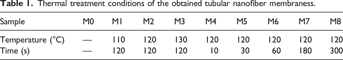
Thermal treatment conditions of the obtained tubular nanofiber membraness.
Membrane characterization
Field-emission scanning electron microscopy (FE-SEM S4800, Hitachi, Japan) was applied to observe the morphology of membrane surfaces and cross-sections after coating with gold. The selective wettability of the membranes was evaluated by measuring the water and oil contact angles, which were tested by drop contact-angle measurements (DSA-100, Kruss, Germany). Liquid entrance pressure (LEP) was tested using a laboratory apparatus at room temperature. The pressure was increased gradually until water penetrated the membrane; this pressure was considered the LEP. The pore size and distribution were tested using an automated capillary flow porometer (CFP-1100A, PMI, USA). The diameters of the nanofibers and thicknesses of the obtained membranes were measured in Nanomeasurer 1.2 software.
The tensile properties were determined at room temperature by an electromechanical testing machine (5969, INSTRON Corporation, USA). The gripping range and tensile rate were 50 mm and 50 mm·min−1, respectively.
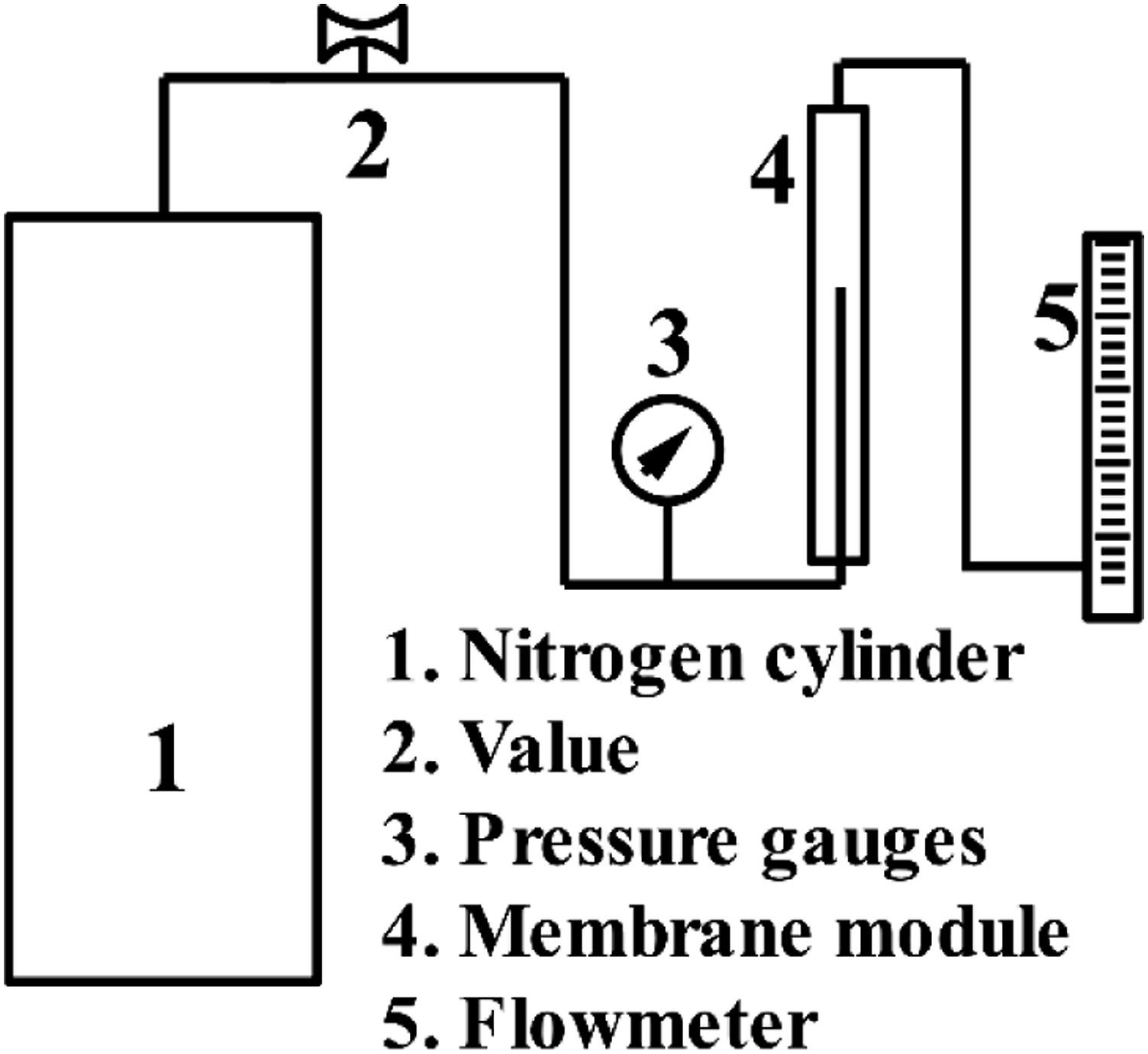
The N2 flux was determined by equation (1): Schematic diagram of the N2 flux testing device.
The porosity, which determined the weight of butanol contained in membrane pores, was assessed by the gravimetric method and calculated by equation (2):
Preparation of water-in-oil emulsions
Compositions of various surfactant-stabilized water-in-oil emulsions.

Water-in-oil emulsions separation experiments
The separation experiment was carried out with a vacuum system under 0.08 MPa and the filtration rate was calculated by equation (3):
Images of the feed solution and permeated solution were obtained by optical microscopy (BX43, Olympus). The water content of the emulsions was tested using a Karl Fischer moisture titrator (C20, Mettler Toledo, Switzerland). The separation efficiency was calculated as follows:
Results and discussions
Characterization of PVDF-HFP/GE TNMs
The surface and cross-sectional morphology of the obtained membranes are shown in Figure 2. In Figure 2(a), it can be clearly seen that, after the electrospinning process, the TNMs exhibit a good hollow fiber structure and a nanofiber layer that is firmly coated on the PET braided tube, which was used as the supporting material of the nanofiber layer and provides the membrane with excellent mechanical properties. The special tubular shape enhances the surface area and packaging capacity, which are important parameters in membrane design. Furthermore, it is clear that the nanofiber layer wrapped the PET braided tube tightly, which indicates good interconnectivity between the fiber layer and braided tube. To investigate this further, Figure 2(b) shows an enlargement of the surface of a pristine membrane. The membrane surface is composed of cylindrical and smooth nanofibers and presents a networked porous structure. In addition, Figure S3 shows a TEM image of the morphology of PVDF-HFP/GE tubular nanofiber membranes. It can be clearly seen that GE nanosheets are embedded in the PVDF-HFP nanofibers and distributed along the nanofiber axis, indicating that they were successfully doped into the PVDF-HFP nanofiber membranes. SEM images of the obtained TNMs: (a) whole cross-section, (b) enlargement membrane surface.
According to our previous paper,
18
it is known that the nanofiber layer becomes firmly coated on the PET woven tube, which provides excellent mechanical strength to the PVDF-HFP/GE TNMs. As shown in Figure S4, the breaking strength and breaking elongation of the TNMs were as high as 360 MPa and 50%, respectively, which is attributed to the PET woven tube. The enlarged SEM image shows a networked porous structure with smooth nanofibers and mean, maximum, and minimum fiber diameters of 99 nm, 177 nm, and 67 nm, respectively (Figure 3(a)). Characteristics of pristine TNMs: fiber diameter distribution (a), porosity and N2 flux (b), pore size distribution (c), and water and oil contact angle (d).
As shown in Figure 3(b), the nanofiber membranes also exhibit excellent permeability, which can be confirmed by the high porosity and N2 flux. Moreover, the pore size distribution is tabulated in Figure 3(c). It can be clearly seen that the pore sizes were mainly distributed from 173.1 nm to 319.8 nm. The mean, largest, and smallest pore sizes were 298.6 nm, 319.8 nm, and 173.1 nm, respectively. The hydrophobicity and lipophilicity of the PVDF-HFP/GE TNMs were also investigated by measurement of water and oil contact angles (Figures 3(d) and S5). The PVDF-HFP/GE TNMs had a water contact angle of 140.5 ± 1.5° which indicates their outstanding hydrophobicity. Additionally, the PVDF-HFP/GE TNMs had great lipophilicity and could be wetted quickly, with an oil contact angle reaching 0°.
Effects of thermal treatment conditions
Effects of thermal treatment temperature
To investigate the optimal thermal treatment conditions, different temperatures and times were applied to the PVDF-HFP/GE TNMs. Firstly, thermal treatment temperature was investigated; the corresponding SEM images and fiber diameters are shown in Figure 4. The results indicate that thermal treatment temperature had a significant effect on membrane morphology. It is clear that the TNM surfaces became denser and their pore size became smaller with increases in treatment temperature from 110°C to 130°C. In addition, the fiber diameter increased gradually as the temperature increased from 110°C to 120°C. These nanofibers fused and gradually lost their fibrous structure as the temperature increased to 130°C. As Figure 4 (b2) shows, graphene was exposed to the membrane surface after thermal treatment, which provided it with an ideal structure and hydrophobicity.
25
Surface morphology and fiber size distribution of TNM samples. a) M1, b) M2, and c) M3.
We also evaluated the effect of thermal treatment temperature on pore size by measuring the pore size distributions of the obtained membranes. As Figure 5 shows, the pore size distribution remained unchanged after thermal treatment at 110°C. However, the pore sizes after treatment at 120°C and 130°C were distinctly smaller and decreased with temperature. The pore size distribution became narrower with increases in thermal treatment temperature. This is ascribed to the changes in membrane structure, as mentioned in the above section. Generally speaking, it is normal to obtain a smaller pore size when the nanofibers melt and fuse together after thermal treatment. The trends observed in our study are consistent with other literature.18,25–26 Pore size distributions after thermal treatment at 110°C, 120°C, and 130°C for 120 s.
The effect of thermal treatment temperature on membrane performance is shown in Figure 6. As shown in Figure 6(a), the water contact angles of the TNMs treated at 110°C had no obvious difference from those of the original membrane. At 120°C, the water contact angle increased visibly, which is because of the exposed graphene. However, at 130°C, the water contact angle decreased sharply to 87° due to a smoother membrane surface being formed. Meanwhile, the membrane LEP had no obvious change under a temperature increase from 110°C to 120°C and then decreased sharply to 0.078 MPa with a further increase to 130°C, which is due to a decrease in hydrophobicity. Water contact angle and LEP (a) and porosity and membrane thickness (b) after thermal treatment at temperatures of 110°C, 120°C, and 130°C for 120 s.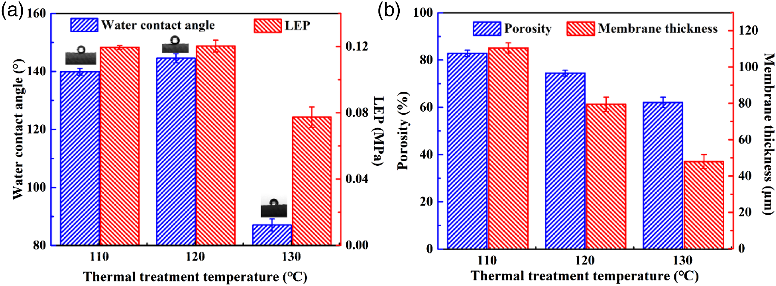
As shown in Figure 6(b), the porosity of the original membrane was as high as 84.51 ± 1.01%. After 120 s of thermal treatment, the porosity decreased by 25%, from 82.80 ± 1.21% to 62.06 ± 2.26% as the temperature increased from 110°C to 130°C. As shown in the SEM images, the membrane surface became more compact as the treatment temperature increased from 110°C to 130°C. Meanwhile, the membrane thickness decreased with treatment temperature, which illustrates that the nanofibers became closer.
Effects of thermal treatment time
Figure 7 shows the fiber diameters and surface morphology of TNMs obtained under different thermal treatment times. The results indicate that the adhesion of nanofibers became more prominent with increases in time. As shown in Figure 7, the surface morphology only changed slightly with increases in treatment time from 10 s to 30 s. When the treatment time further increased from 60 s to 120 s, the nanofibers began to fuse gradually and the membrane surface became rougher. In addition, more graphene was exposed to the membrane surface at the treatment time of 120 s. When the thermal treatment time was further increased from 180 s to 300 s, these nanofibers fused together and the membrane surface became too dense to retain its fibrous structure. Furthermore, most of the graphene was wrapped in fused polymer. Surface morphology and fiber size distribution of TNM samples. a) M4, b) M5, c) M6, d) M2, e) M7, and f) M8.
The pore size distributions of TNMs after thermal treatment for different times are shown in Figure 8. The mean, smallest and largest pore sizes are tabulated in Table 3. It is clear that with increases in thermal treatment time, the mean pore size gradually decreased from 425.9 nm to 180.2 nm. The pore sizes of the membranes were distributed within 0.2–0.4 μm after treatment for < 60 s and the pore size distribution narrowed with increases in treatment time. As the time increased further from 120 s to 300 s, the pore size was mainly distributed within 0.15–0.25 μm and the distribution was much narrower than those of the three membranes mentioned above. This can be explained by the fact that no obvious fusion occurred at thermal treatment times < 60 s, while entire nanofibers fused and plugged membrane pores at times of 120 s to 300 s. In addition, the pore size distribution became unimodal at 120 s to 300 s. The main reason is that entire nanofibers fused and smaller pores were blocked, while larger pores became smaller. Pore size distributions at different thermal treatment times (10–300 s) at 120°C. The mean, minimum and maximum pore size of obtained TNMs with thermal treatment time from 10 s to 300 s for 120°C.

To investigate the effect of thermal treatment time on membrane properties, the membranes were thermally treated at 120°C for various times from 10 s to 300 s. The water contact angle increased slightly from 140.45 ± 1.18° to 144.96 ± 1.10° with thermal treatment of 10 s to 120 s, and then decreased sharply to 121.16 ± 1.71° with further time. It was also found that the LEP of the TNMs did not change much and remained at ∼0.12 MPa with increases in treatment time from 10 s to 120 s, and then decreased to 0.09 MPa with further time due to the lower hydrophobicity of the obtained membranes.
The membrane porosity decreased by 25% (from 84.51 ± 1.01% to 63.29 ± 2.62%) as the thermal treatment time increased from 10 s to 300 s (Figure 9(b)). With further increases in time from 60 s to 300 s, the nanofibers fused and the membrane surface became denser. The optimal thermal treatment conditions for PVDF-HFP/GE TNMs are 120°C and 120 s. The membrane thickness decreased with increases in thermal treatment temperature, which illustrates that the nanofibers became closer. Water contact angle, LEP (a) and porosity, membrane thickness (b) changing with thermal treatment time from 10 s to 300 s for 120°C.
Figure 10 shows schematic diagrams of the obtained TNMs before and after thermal treatment. During thermal treatment, the PVDF-HFP/GE nanofibers melted together and formed an integrated fibrous network consisting of continuously connected fibers and a porous structure. In addition, the melted nanofibers reduced the porosity between fibers and optimized the membrane pore structure by losing their individual nanofiber structures. After thermal treatment, some GE was exposed on the membrane surface, which provided a rougher membrane surface and higher hydrophobicity. This is attributed to the outer nanofibers melting first and the inner fibers remaining intact. The outer graphene was blocked by the inner fibers and could not move to the inside with the molten nanofibers. Furthermore, graphene has a rigid structure27–28 while PVDF-HFP is a flexible polymer,
26
which suggests that the polymer chains could move easily while the graphene moved with difficulty or not at all. Schematic diagram of PVDF-HFP/GE TNMs before and after thermal treatment.
It is well known that the thermal treatment temperature and time are two main factors affecting molecular motion. 23 On the other hand, the energy required for molecular motion increases with thermal treatment temperature. 29 In addition, the intermolecular distance increases with temperature due to volumetric expansion, which accelerates the relaxation process and molecular motion. 30 On the other hand, the motion units need to overcome internal frictional resistance to move, which does not occur quickly, indicating that thermal treatment time has a significant effect on the membrane structure. 31 Therefore, the treatment temperature and time were investigated.
Oil/water separation performances of PVDF-HFP/GE TNMs
To evaluate the emulsion separation capability of the PVDF-HFP/GE TNMs, various surfactant-stabilized water-in-oil emulsions were prepared. The separation process was performed on the obtained membranes after 120 s of thermal treatment at 120°C (M2). As shown in Figure 10(a), the thermally treated TNMs could separate the different emulsions with high filtration rates; specifically, 497.48 ± 13.35 L·m−2·h−1 for SSE-1, 385.60 ± 6.44 L·m−2·h−1 for SSE-2, 241.41 ± 18.87 L·m−2·h−1 for SSE-3, and 174.13 ± 7.83 L·m−2·h−1 for SSE-4. The differences may be due to differences in the viscosity of the feed solution. Trans-membrane resistance increases with viscosity, which results in a lower filtration rate. Moreover, the prepared TNMs also possessed high separation efficiency of up to 99.16% for SSE-1, 99.58% for SSE-2, 99.19% for SSE-3, and 99.52% for SSE-4. The separation efficiency of the obtained membrane is reflected in the calculated water contents of the feed solution and filtrated solution. The high separation efficiency was attributed to the appropriate pore structure as well as the excellent hydrophobicity conferred by thermal treatment. In addition, compared with pristine membrane (Table S1), the separation efficiency of the obtained membranes after thermal treatment exhibited an obvious increasing trend, while the filtration rate only had a slight decrease. Optical microscope images and droplet distributions of membrane SSE-3 before and after filtration are exhibited in Figure 11(c). It is clearly seen that most of the water droplets in the feed solution could be separated by the TNMs. The results indicate that the obtained TNMs have an outstanding separation capability for water-in-oil emulsions. Filtration rate (A), separation efficiency (B), and optical microscope images and photographs of emulsions before and after filtration. Size distribution of feed and filtrate with membrane SSE-3 (C) and change in filtration rate over 10 cycles (D).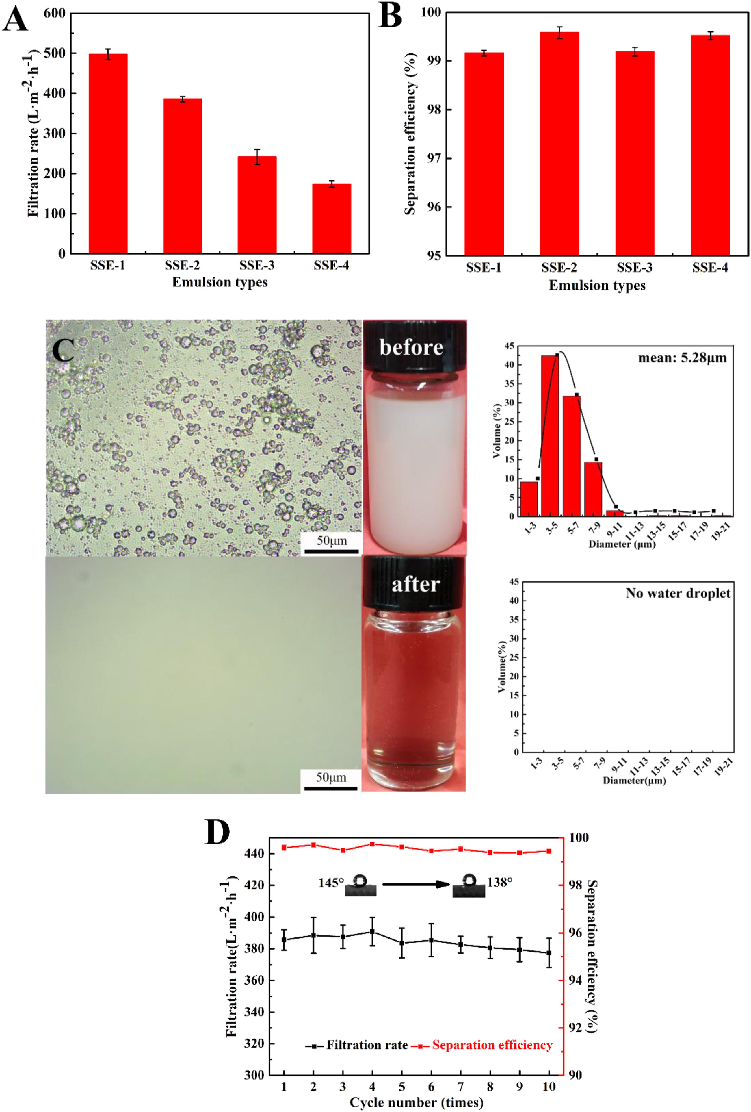
The stability of the PVDF-HFP/GE TNMs during long-running processes is an important property. In this study, a 10-cycle separation experiment was performed; the results are shown in Figure 11(d). Over 10 cycles, the water contact angle only decreased slightly. The obtained TNMs also showed stable filtration rates and separation efficiency after 10 cycles, which indicates an outstanding anti-fouling property.
Conclusion
This paper reports a novel and simple approach to designing and fabricating PVDF/GE TNMs that have a special structure. The effects of thermal treatment conditions on the structure and performance of PVDF-HFP/GE TNMs were investigated. The optimum thermal treatment conditions were 120°C for 120 s. After thermal treatment, more graphene was exposed to the membrane surface and the obtained TNMs possessed excellent oil/water selective wettability. In addition, the after thermally treated TNMs possessed an optimal pore structure and separated various water-in-oil emulsions at high filtration rates (497.5 ± 13.3 L·m−2·h−1 under −0.08 MPa) and separation efficiency (>99%). Moreover, the TNMs exhibited excellent stability, high porosity, and antifouling performance. Therefore, these TNMs can be effectively used in numerous environmental protection applications.
Footnotes
Declaration of conflicting interests
The author(s) declared no potential conflicts of interest with respect to the research, authorship, and/or publication of this article.
Funding
The author(s) disclosed receipt of the following financial support for the research, authorship, and/or publication of this article: The study received start-up funding from the Hebei University of Science and Technology (1181455) and the Key Research and Development Project of Hebei Province (20271202D).