
Abstract
This study reveals the mechanical and interfacial bonding properties of glow discharge oxygen plasma modified ultrahigh molecular weight polyethylene (UHMWPE)/vinyl ester composites modified by oxygen plasma. The composites’ flexural, tensile, and impact-resistant properties were estimated, and the failure mechanism was analyzed by acoustic emission (AE) testing. The flexural stress, tensile stress, and impact-resistance force of the modified three plain weave structures composites are 193.37–734%, 11–15%, and 16–17% higher than those without modification. It depends on flexibility, interfacial bonding strength, reinforcement structure, and stiffness. In addition to the flexural properties, the tensile and impact properties increase with fiber volume fraction. In the AE test, the flexural and tensile cumulative energies without modification are 9230.42 mV*mS and 1.735 V*S higher than modified materials. The characteristic frequency range of each failure mechanism is determined by cluster analysis. Low, medium, and high frequency correspond to matrix cracking, fiber/matrix debonding, and fiber breakage. Oxygen plasma contributes to the wettability of the reinforcement and the interfacial bonding strength, resisting cracking growth.
Keywords
Introduction
Ultrahigh molecular weight polyethylene (UHMWPE) fiber is low-cost, lightweight, and has excellent strength and modulus. It is often used as reinforcement in composites. Lightweight fiber-reinforced polymer composites are widely used in aerospace, automotive, and marine industries because of their reduced weight and unique stiffness properties.1,2 However, they do not bond well with resin due to their poor surface adhesion. Therefore, UHMWPE fiber is usually used to improve its surface roughness and increase the number of polar groups on the surface to improve the wettability of the combination with resin. The main modification methods of UHMWPE include liquid-phase oxidation, 3 radiation grafting, 4 surface coating modification, 5 corona discharge, and plasma modification. 6 Compared with surface coating, radiation grafting, and chemical modification, plasma modification is simpler, more uniform, and has little influence on material properties. Different gas media can be selected according to material properties. The surface activity of fiber and the interfacial bond between fiber and matrix were significantly improved. The bond strength between fiber and matrix is important in studying composites’ mechanical properties. The damage process of composite materials is more complex than that of single materials, usually manifested as matrix cracking, interfacial cracking, fiber fracture, and interlayer separation. Acoustic emission (AE) technology has become an important means of studying composites’ damage failure mechanisms. There are few types of research on AE technology’s mechanical damage detection of UHMWPE composites. Therefore, AE signals generated in the damage process of UHMWPE composite can be analyzed to remedy its deficiency. The relationship between AE characteristics and damage behavior is established. The characteristic frequency range of each failure mechanism is determined by cluster analysis.
Plasma modification technologies include low-pressure and atmospheric pressure plasma. The carbon-free radicals on the surface react with reactive oxygen species in the ambient air, enhancing the roughness and activity of reinforcer surface. At present, according to YAN et al. 7 the effects of plasma sources and modification methods on the structure and properties of high-performance fiber-reinforced composites and their mechanism are discussed in this study. The results of cold plasma treatment, functional degree, interface performance improvement, and functional groups are summarized. Domínguez-Díaz et al. 8 The wettability of ultra-high molecular weight polyethylene surfaces was modified by controlling exposure time and distance by atmospheric plasma treatment. Plasma treatment can modify crystallinity and roughness of UHMWPE surface, affecting the material’s wettability, a desirable tribological trait. Atmospheric plasma treatment significantly improves the surface wettability of UHMWPE. When treated UHMWPE approaches structural stability, the final wettability value is better than that of untreated material. Arefi-Khonsari et al. 9 This work demonstrates that helium/oxygen dielectric barrier discharges impart hydrophilic functional groups to the surface. Thus, the bioactivity of UHMWPE was enhanced without affecting the biocompatibility of polymer.
Using UHMWPE composites in many structures increases the need for non-destructive structural integrity testing.10,11 Acoustic emission can identify delamination damage of composite materials and the transient elastic wave propagation caused by the sudden release of internal energy of materials.12,13 Zhang et al. 14 Acoustic emission signals of glass fiber/epoxy resin composites can correspond to matrix cracking, fiber/matrix debonding, and fiber breakage. The characteristic frequency range of each failure mechanism can be determined by cluster analysis. Zhang et al. 15 The three-point flexural method is utilized to test three types of 3D angle-interlock specimens, carbon, hybrid (carbon/UHMWPE), and UHMWPE, in the warp and weft directions. Acoustic emission tests were employed to assess composites' damage initiation/evolution. The results indicate that hybrid structures significantly affect mechanical behaviors, damage models, and failure mechanisms.
In this project, glow discharge oxygen plasma was primarily used to modify the surface of UHMWPE reinforcement 16 and improve interfacial bonding. The composite was prepared by VARI 17 process. The flexural properties,18–20 tensile properties, 21 and impact properties 22 of materials were studied using AE testing. The failure mechanism of modified and unmodified 23 is discussed.
Experimental
Materials
Ultrahigh molecular weight polyethylene twisted filament fineness 600D was purchased from Suowei special thread belt co. LTD, Dongyuan, China. The density of UHMWPE reinforcement was 160 threads/10 cm, 200 threads/10 cm and 240 threads/10 cm; 901 vinyl ester resin and curing agent were provided by Baiyi Chemical co. LTD, Jining, China.
Preparation of composites
Ultrahigh molecular weight polyethylene reinforcement was trimmed into a dimension of 30 cm × 18 cm. Glow discharge plasma equipment (HTP-300, Yian Technology co. LTD, Beijing, UK) is revealed in Figure 1(a). The oxygen plasma modified power parameter was 200W, the modification time was 3 min, and the gas flow rate was 8 sccm. The scanning electron microscope (SEM) in Figure 1(a) displays that the plasma modified surface becomes rough, and an etching layer appears. Simultaneously, there are granular settings aggregated by plasma etching on the fiber surface. Plasma modification is a uniform and effective method for fiber surface modification. It has little effect and will not cause great failure to the mechanical properties of fiber. Processing flow chart (a) glow charge plasma modification, and (b) VARI.
Specifications of UHMWPE/vinyl ester composites with and without oxygen plasma modification.

UHMWPE: Ultrahigh molecular weight polyethylene.
Testing methods
Water contact angle test
The water contact angle was tested using JC2000D1 contact angle measuring instrument (Zhongchen digital technology equipment co. LTD, Shanghai, China) by employing ASTM D5946 standard. The water contact angles of unmodified and modified reinforcers were tested. The influence of plasma on the surface wettability of reinforcement is discussed. Five samples of each type were tested separately, and the results were analyzed.
Flexural test
The Flexural test of UHMWPE reinforced composites was evaluated using a UTM5105 electronic universal testing machine according to ASTM D7264 standard. The sample was trimmed into a rectangle with dimensions of 120 mm × 20 mm. Five samples of each type were tested separately, and the results were analyzed. The span was 16 times the laminate thickness, and the loading speed was 5 mm/min.
Tensile test
The tensile strength of UHMWPE reinforced composites was evaluated according to ASTM D3039M-2014 standard using a UTM5105 electronic universal testing machine. The sample was trimmed into a rectangle with dimensions of 120 mm × 15 mm. Five samples of each type were individually tested, and the results were analyzed. The clamping distance was 80 mm, and the testing speed was 2 mm/min.
Impact test
The impact resistance was tested using ASTM D7136 standard. AZCJ9302 drop weight impact test machine used a 2 kg and 16 J energy drop hammer. The sample was regulated to 150 mm × 100 mm dimension. Five samples of each type were individually tested, and the results were analyzed.
Acoustic emission test
Acoustic emission test was conducted according to ASTM E2076 standard using DS5-8B AE testing machine. The failure dynamic evolution trend of composites was effectively evaluated in the mechanical test. Acoustic emission testing can analyze the internal failure mechanism of materials and provide real-time monitoring. By establishing the relationship between the failure feature frequency and composite failure mechanism, the failure of materials is predicted. Acoustic emission activity intensity and failure source parameters can be characterized by AE energy.
Results and discussion
Wettability of UHMWPE/vinyl ester composites
Figure 2 displays that water contact angles of samples U01 and U03 are 103° and 125°, respectively, and those of samples P01 and P03 are 96° and 115.5°. Ultrahigh molecular weight polyethylene has strong hydrophobicity. With the increase in fiber density, the yarns in the reinforced fiber are arranged more closely due to increased fiber volume fraction. The water contact angle increases gradually, and wettability decreases. The water contact angle of the modified fiber surface is smaller than without modification. Because the fiber is etched, the fiber surface presents different depressions. The crystallinity and roughness of fiber are changed, affecting the adhesion and wettability of fiber surface. The results reveal that plasma modification provides more polar groups for the interface. The interface’s chemical bond density per unit area was increased, and the interfacial force transfer and blocking effect were enhanced. The water contact angle of Ultrahigh molecular weight polyethylene/vinyl ester composites with and without oxygen plasma modification.
Analysis of flexural properties
Flexural strength
Figure 3(a) depicts that elastic deformation of fiber and resin occurs simultaneously at the beginning of flexural. The upper part of the sample is squeezed, and the lower part is stretched. The curved curve grows linearly. When the elastic deformation reaches a certain value, the upper pressure rises, and the shear failure strain, elastic modulus, and elastic deformation occur with the convexity of flexural performance curve. The flexural angles of warp direction samples U01 and U03 are 116° and 135°, respectively, and of P01 and P03 are 137° and 152°. They decreased by 18.1% and 12.6%. As shown in Figure 3(b), the flexural angles of weft direction samples U01 and U03 are 125° and 136°, respectively, and those of samples P01 and P03 are 141° and 159°. They decreased by 12.8% and 16.9%. The fiber volume fraction increases with reinforcement density when all samples are in the warp direction or weft direction. As the content of reinforcement bearing flexural failure increases, composites’ flexural resistance improves. The modification reduces the change of flexural angle. It demonstrates that interface properties are improved, stiffness is increased, elastic deformation recovery is increased, and flexural resistance is improved. Flexural stress-strain curves and flexural angle of composites with and without oxygen plasma modification in (a) warp direction and (b) weft direction.
The meridional and zonal stresses of sample P01 have peaks of 115.12 mPa and 293.6 mPa, as displayed in Figure 3(a) and (b). The flexural stress of without modification specimens increases with increasing density. With modification, the flexural resistance of P01 is the best, and the stress is increased by 193% and 734%, respectively, compared with U01 in warp and weft directions. The results also reveal that reinforcement density of flexural was increased. The contact area of plasma etching is large, and the effect is better because the reinforcement density is low and the structure is loose. Etching pit is beneficial to enhance the stress transfer between the reinforcement and the resin, improve the friction coefficient, and improve the interface performance. It is beneficial to the cooperation of resin penetration and reinforcement. U03 has better flexural performance than P03. The results indicate that the density of reinforcer is large. On the one hand, the modification effect is not comprehensive, the resin infiltration effect is poor, and the adhesion between the reinforcer and the matrix is poor. On the other hand, the mechanical properties of fibers are decreased by etching, and the possibility of interface problems is greater, but the flexural resistance of laminates is reduced. In Figure 3(a), the slope of modified composites is larger than that without modification. The stiffness of composites is determined by the interface properties and modulus and has little relation with flexible reinforcement.
The warp and weft direction specimens in Figure 3 peak stress when the strain is 6.6%. The weft direction specimens bear greater stress and stronger flexural load than the warp direction specimens. Due to high warp density, resin penetration and interfacial bonding are weak, but they reduce flexural resistance. It shows that flexural resistance is related to stiffness.
Of AE analysis of flexural process
Different failure mechanisms occur in the flexural process of composite, such as matrix cracking, fiber/matrix debonding, and fiber breakage. These mechanisms have specific acoustic emission characteristic ranges, such as amplitude, frequency, and energy. 24
In Figure 4, the material undergoes flexural elastic deformation at the initial stage. The primary failure mode is vinyl resin matrix cracking. Figure 4(a) discloses that the number of failures increases rapidly, and the released energy is immense. The main bearing stress changed from composite to UHMWPE reinforcement. When the reinforcement is fractured in a large area, the composite fails. The activity of AE energy increases, as does the cumulative energy, indicating that the composite specimen has entered the failure stage with increased fiber breakage and fiber/matrix interface bonding. Acoustic emission energy of flexural properties of composites. (a) U03 in weft directions, (b) P01, (c) P02, and (d) P03 in warp direction, (e) P01, (f) P02, and (g) P03 in weft direction.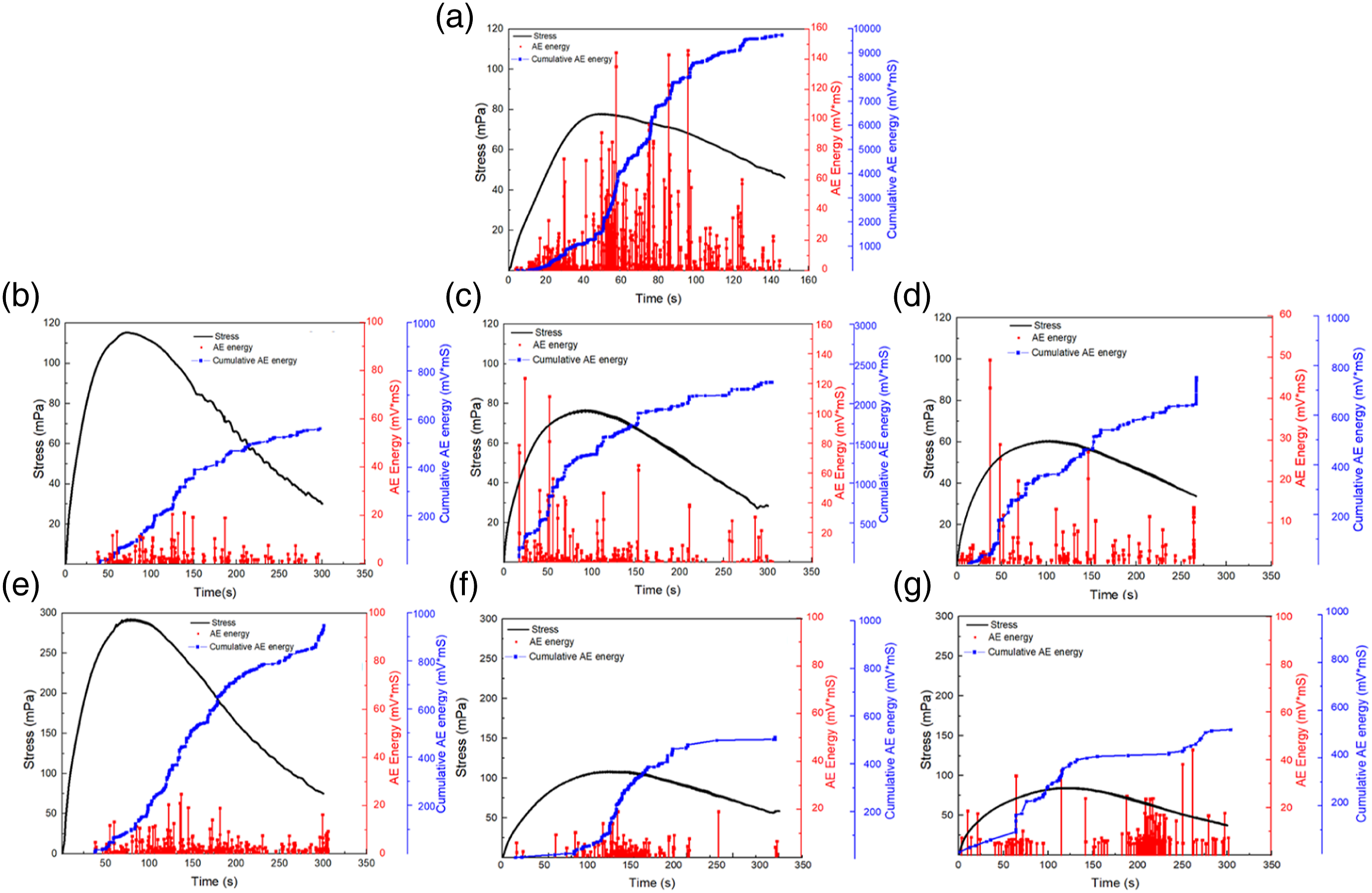
Figure 4(a) shows the U03 sample. Without modification, cumulative energy is more active. With the increase of stress, the cumulative energy increases rapidly in 10–33 s. At 48 s, the stress peaked at 67.21 mPa, and the material began to fail. At 54 s, after 10 s, it reaches a peak AE energy of 144 mV*mS, and the stress reaches 67.06 mPa. The cumulative AE energy is 9750.02 mV*mS. Figure 4(b) displays the P01 warp direction sample. At 11 s, the cumulative energy gradually increases, and the energy gradually becomes active with the increase of stress. At 72 s, the peak stress is 115.12 mPa, and the composite gradually fails. The cumulative AE energy is 584.37 mV*mS. Figure 4(c) presents the P02 warp direction sample, AE energy increases rapidly from the 80 s, and the peak stress is 76.60 mPa. The cumulative AE energy is 2275.68 mV*mS. Figure 4(d) shows the P03 warp direction sample. The cumulative energy increases rapidly at 8 s. The AE energy peak of 123 mV*mS appears at 22 s, and the peak stress reaches 60.62 mPa. The cumulative AE energy is 784.36 mV*mS. Figure 4(e)–(g) depicts P01, P02, and P03 weft direction samples. The trend is similar to that of warp samples. In general, AE energy of sample P01 gradually becomes inactive, and cumulative energy is less than that of P02 and P03. The weft direction has better flexural resistance than the warp direction, and AE energy is less active when damaged. Part of the reason may be that beating-up causes warp wear in the fabric formation process. The other part may be that the weft density is lower than the warp density and the modification effect is better. The stiffness and flexural resistance of the composite are improved.
Figure 4 displays that the looser the structure of modified composite reinforcement, the greater the increase of stiffness and elastic modulus. The AE energy and cumulative AE energy decrease when the maximum stress is reached. The interfacial bonding strength and flexural resistance of composites are increased. Three-component cluster analysis is used to examine the damage mechanism of composites by analyzing frequency and amplitude.
The three damage modes of matrix cracking, fiber/matrix debonding, and fiber breakage correspond to low, medium, and high-frequency AE signals. When Clusters 1, 2, and 3 appear, their frequencies are mainly distributed in 0–100 kHz, 10–200 kHz, and >200 kHz, respectively. Clusters 1, 2, and 3 overlap within the amplitude distribution interval and different damage modes appear simultaneously. Therefore, according to cluster results, it can be considered that AE signal characteristics of Cluster 1 correspond to the matrix cracking. The fiber/matrix debonding can correspond to AE signal characteristics of Cluster 2. Cluster 3 corresponds to fiber breakage. 25
Figure 5(a) shows the U03 sample of Cluster 1, 2, and a small amount of Cluster 3, and the peak frequency reaches 277 kHz. Compared with Figure 5(b)–(g), the number of Cluster 1 and 2 frequencies decreased, and Cluster 3 did not appear. At frequency <200 kHz, the failure probability of fiber/matrix interface decreases. The fiber/matrix debonding phenomenon of warp direction P03 is more than that of U03, and the modification effect is insignificant. It is proved that the modified composites material’s interfacial bonding properties and overall structural properties are better than the unmodified ones. The flexural angle increases gradually, and flexural resistance increases. After modification, matrix cracking and fiber/matrix debonding occurred in the flexural test. Cluster analysis of flexural properties of composite (a) U03 in both directions (b) P01, (c) P02, and (d) P03 in the warp direction, (e) P01, (f) P02, and (g) P03 in the weft direction.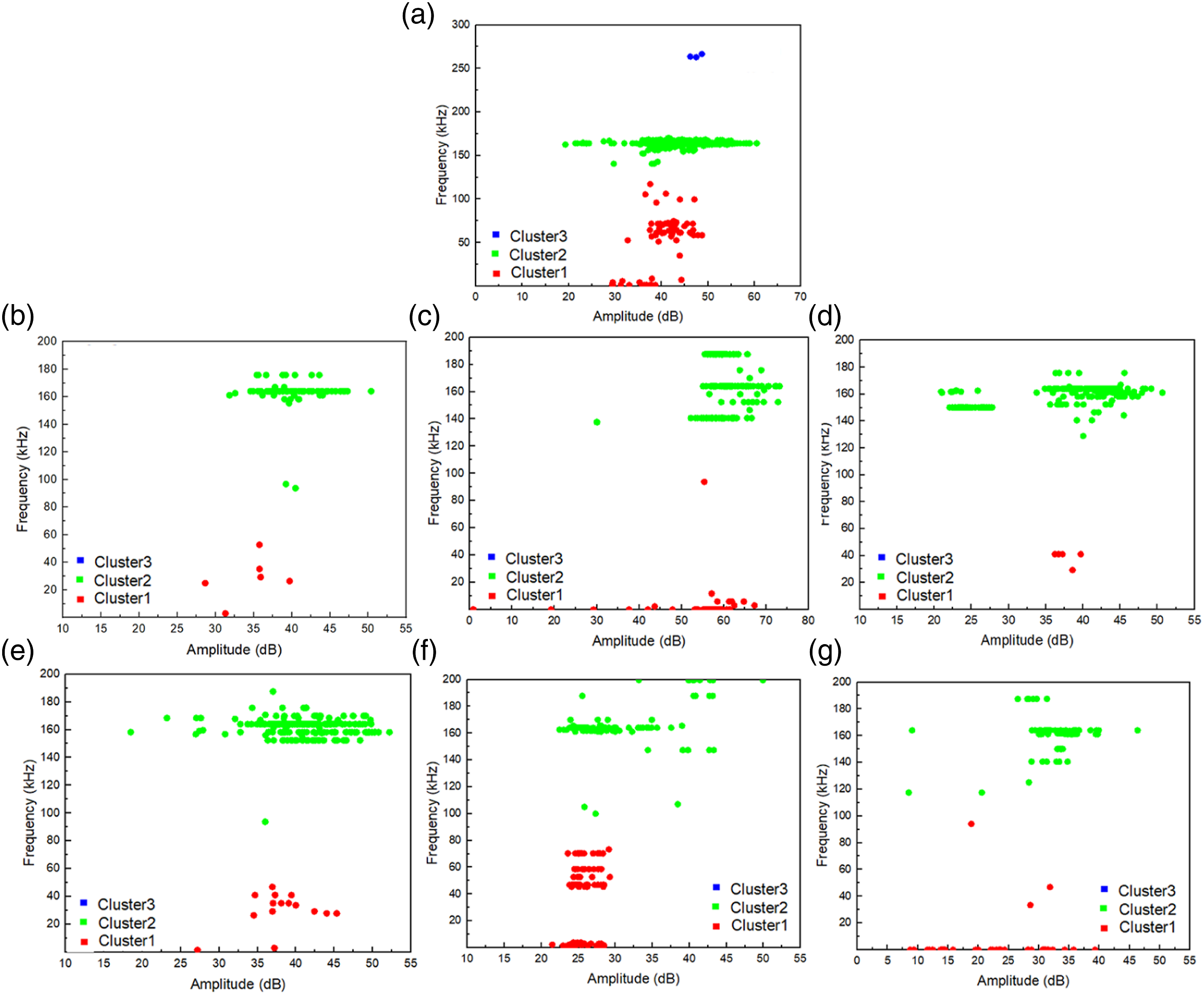
It can be observed through SEM that the failure with modification is matrix cracking and fiber/matrix debonding. Figure 6(a) shows that matrix cracking is the first failure in flexural loading. In flexural tests, the substrate is in the outermost layer, while the bottom undergoes tensile stress and the top undergoes compressive stress. Figure 6(b) and (c) displays the fiber/matrix debonding is due to the failure of matrix, and then the reinforcement is delamination from the matrix without fiber breakage. The reinforcement is flexible with a small force, providing the required bearing capacity for matrix, interfacial, and the final flexural sample failure. The results of SEM characterization are the same as cluster analysis. Scanning electron microscope photographs of interlaminar flexural failure morphology (a) P01, (b)P02, and (c) P03 in the warp direction.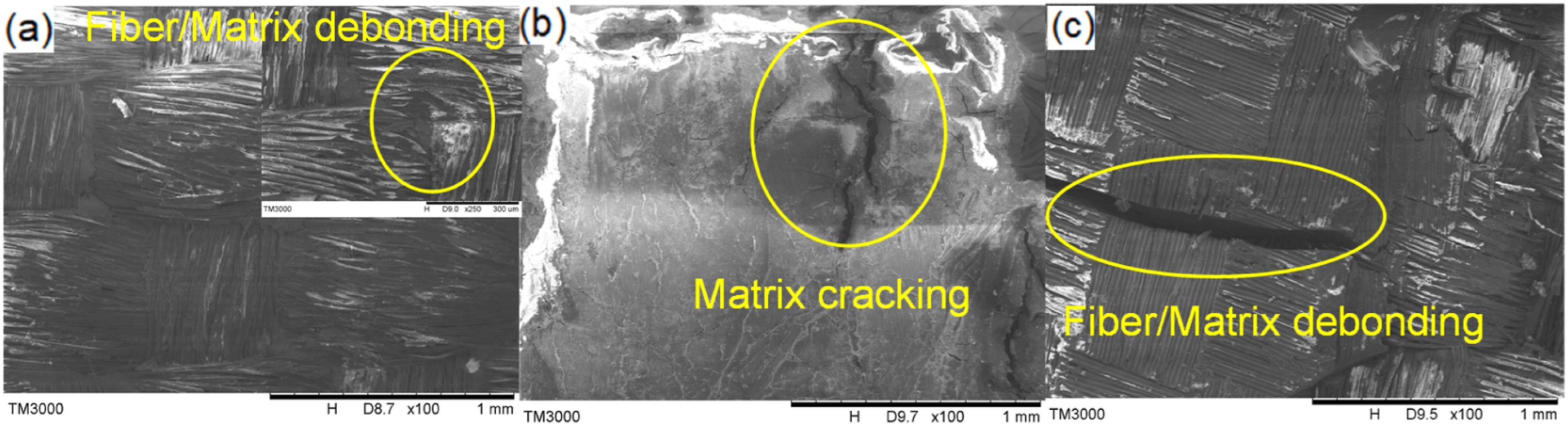
Analysis of tensile properties
Tensile strength
Figure 7 depicts the beginning, where the strain increases directly with the stress, and the slope approximates the material’s elastic modulus. Then, the slope of the curve slows down and produces plastic deformation. When the peak stress is reached, the material’s bearing capacity is lost. The sample U03 of tensile strain is 8.62%, and the stress is 279.48 mPa. P03 tensile strain is 6.78%, and the stress is 324.16 mPa. Compared without modification, the tensile stress increased by 15%, and the tensile strain decreased by 21.3%. The mechanical properties of composite are mainly related to the interfacial properties and the breakage strength of reinforcements. The density of reinforcement increases, as does the fiber volume fraction and tensile strength. Tensile stress-strain curves of composites with and without oxygen plasma modification in the warp direction.
Figure 7 shows that with modification, the slope is higher than without modification, and the degree of stiffness and interfacial performance of the composite are improved. The tensile strain without modification specimens is concentrated at 8%, while it is concentrated at 6–7% with modification specimens, and the strain is significantly reduced. Plasma modification etches the reinforcement so that the breakage strength of reinforcement decreases. However, the effect was insignificant, the friction coefficient increased, and the reinforcement and the matrix cooperated to resist tensile failure. Due to increased stiffness, the load decrease is more severe when the failure occurs than in the unmodified composites.
Acoustic emission analysis of tensile process
Figure 8 shows that the initial stage is elastic deformation. In the failure growth stage, it is mainly resin cracking. Then, the number of failures increases, the fiber/matrix debonding, and the stress is transformed into reinforcement. When UHMWPE fiber breaks greatly, the composite fails. The activity of AE energy increases, and the cumulated energy increases rapidly. It indicates that fiber breakage and fiber/matrix interface intensify at the failure stage. Acoustic emission energy of flexural properties of composites (a) U03, (b) P01, (c) P02, and (d) P03 in the warp direction.
Figure 8(a) shows the U03 sample. The cumulative energy is more active than that with modification samples. In the initial stage, the cumulative energy appears with increasing stress until reaching a larger value of 279.48 mPa. After 2 s, the peak AE energy is 0.097 V*S, after which the material gradually fails, and the cumulative AE energy is 2.37 V*S. Figure 8(b) shows the sample P01. When AE energy is 63 s, the cumulative energy gradually increases, and the energy gradually becomes active with the increase of stress. At 154 s, the peak AE energy is 0.034 V*S, and the stress reaches the larger value of 282.26 mPa, the material begins to fail. The cumulative AE energy is 0.74 V*S. Figure 8(c) shows the sample P02, in which the cumulative energy begins to appear at 23 s, and the stress is 315.94 MPa at 193 s. Meanwhile, the peak AE energy is 0.032 V*S. The cumulative AE energy is 0.617 V*S. Figure 8(d) shows the sample P03, in which the AE energy appears from the 20 s, and the stress reaches 324.16 mPa at 183 s. Simultaneously, the peak of AE energy is 0.029 V*S. The cumulative AE energy is 0.562 V*S. The cumulative energy of modified sample is delayed compared with unmodified one. Due to better interfacial bonding strength with modification, there is less elastic deformation and less tensile damage at the beginning of tension. The looser the reinforcement structure, the more obvious the tensile stress increases after modification. At the maximum stress, AE energy peak appears almost simultaneously. It is demonstrated that irreversible plastic deformation occurs initially, and damage accumulates in the composite. Then, the pressure is greatly reduced, the energy is released, and the material fails. It demonstrates that AE energy can predict the internal damage of composite material. However, a single characteristic parameter of AE signal cannot fully reflect the real AE response behavior. This requires multi-parameter analysis and processing of AE signals. A three-component cluster analysis analyzes the frequency and amplitude to conveniently observe the failure mechanism failure.
When Clusters 1, 2, and 3 appear, their frequencies are mainly distributed in 0–100 kHz, 100 - 200 kHz, and >200 kHz. Clusters 1, 2, and 3 overlap within the amplitude distribution interval and different damage modes appear simultaneously.
Figure 9 displays that Clusters 1, 2, and 3 appeared with and without modification. The tensile sample with and without modification is thought to have experienced matrix cracking, fiber/matrix debonding, and fiber breakage. The number of modified composite materials in Clusters 1, 2, and 3 decreased. The interfacial bonding property of modified composite is improved. P02 has the least damage. P01 has more matrix cracking, indicating that fiber volume fraction is less, the resin content is high, and more matrix cracking occurs. P03 has more Cluster 3, indicating that its modification is not comprehensive, and more fiber breakage occurs. Cluster analysis of tensile properties of composite (a) U03, (b) P01, (c) P02, and (d) P03 in the warp direction.
The failure morphology of composites materials was characterized by SEM. Figure 10(a)–(f) shows the tensile failure, resulting in composites appearing with fiber/matrix debonding, fiber breakage, matrix cracking, and delamination. Scanning electron microscope characterization results are the same as those of cluster analysis. It is proved that the mechanical properties of composites are mainly linked to the interfacial properties and the breakage strength of reinforcements. Scanning electron microscope photographs of interlaminar tensile failure morphology (a) P01, (b) P01, (c) P02, (d) P02, (e) P03, and (f) P03 in warp direction.
Analysis of impact properties of composite laminates
Impact on mechanical properties
When the impact head makes contact with the sample, energy consumption begins, and the sample absorbs and deforms the kinetic energy of drop weight. When the drop weight reaches the lowest point, part of kinetic energy is transformed into strain energy, and part is consumed by failure and friction. The drop weight then begins to rebound, resulting in elastic unloading. The recoverable elastic strain energy is transformed into the kinetic energy of the drop weight until it is separated from the composite. The final energy of curve represents the total energy consumption, which is mainly the sum of the failure energy consumption of composite.
Figure 11(a) shows that with modification, the time is advanced when the composite material reaches the peak energy during impact, and the final energy consumption is decreased. Energy dissipation reflects the damaged state of composite material. The higher the energy dissipation is, the more serious the damage is during impact. P03 sample minimum energy consumption is 13.43 J, the energy dissipation rate was 83.9%, and the damage was the least. The area under the impact force-displacement curve represents the energy dissipation by the composite material during impact. The energy dissipation reflects the damaged state of composite material. The higher the energy dissipation is, the more serious the damage is during impact. The energy dissipation at the initial position of the curve is very low because the deformation inside the sample is minimal during loading. Then, the slope of curve increases, and the energy dissipation by the sample comes from the deflection and internal damage. In the end, the energy stays the same. With increasing the warp density, the impact resistance is significantly improved. The deformation caused by impact on the composite material, and the recoverable elastic deformation are small. There is low total energy consumption due to low energy absorption. The energy consumed difference between U01 and P01 is 1.22 J. Due to the low density, the reinforcement modification is more comprehensive. The reinforcement is more closely combined with the matrix and the impact resistance increases significantly. Impact of composite with and without oxygen plasma modification in (a) energy-time curve (b) impact force-displacement curve (c) dent depth.
The impact force curve rises steadily after the impact head contacts the composite material. The deformation of composite material increases, the stress is redistributed, and the drop weight resistance rises. The impact force curve rises steadily after the impact head contacts the composite material. The deformation of composite material increases, the stress is redistributed, and the drop weight resistance rises. Drop weight and composite residual center displacement are displaced when the impact force is zero. It is the final impact deformation and measurement of dent depth to represent it.
Figure 11(b) shows that the impact forces of U01 and P01 samples are 2297 N and 3014.67 N, respectively, increasing by 31.2%, and those of U03 and P03 samples are 2706 N and 3501 N, increasing by 29.3%. With density increase, the impact resistance significantly increases, proving that the main impact resistance is the breaking strength of reinforcement. The impact force difference of U01 and P01 samples is 409 N. The reinforcement with low density has a better modification effect and interfacial performance. The impact properties are mainly related to the interfacial properties and the breakage strength of reinforcements. The interfacial bonding effect is good and the stiffness is improved with modification. Once failure occurs, the load drop is more severe than the reinforcement without modification.
Figure 11(c) depicts that the dent depths of U01, U02, and U03 are 4.2, 3.5, and 3.2 mm, respectively. The dent depths of P01, P02, and P03 are 2.9, 2.4, and 2.2 mm, respectively, with a decrease of 30.9%, 31.4%, and 31.3%. The dent depth decreased obviously with and without oxygen plasma modification. The bonding force between reinforcement and matrix is improved with modification. This makes the fiber and resin jointly bear the impact force synergistic resistance deformation, improves the impact force resistance drop weight, and reduces the dent depth. However, the fiber fracture of composite material gradually changes into energy dissipation mode, and a small number of fiber fractures after modification, maximizing the fiber reinforcement effect and improving the material’s impact resistance.
Conclusion
In this study, the mechanical properties and interfacial bonding properties of composites were modified by oxygen plasma, and the failure mechanism was tested by acoustic emission testing. By establishing the relationship between the failure characteristic frequency and the damage model of composite material, the variation of the main components of AE signal of UHMWPE composites during damage was investigated.
The results reveal that plasma modification can etch the reinforcement, change its wettability, improve the interface bonding, cooperate with the matrix to resist destructive force, and improve the mechanical properties. The lower the fiber volume fraction of composite material, the better the modification effect and the greater the increase of mechanical properties. The best effect modified composite of 160 threads/10 cm. The etching area of plasma is large due to the loose structure of low-density reinforcer. After plasma modification, 160 threads/10 cm composite flexural resistance is the best. The primary resistance to its flexural damage is the interface bond and stiffness. Tensile resistance and impact resistance show that the composite laminate with 240 threads/10 cm has better resistance to damage. When the composite laminate is subjected to impact force, the tensile force mainly acts on the interface bonding and reinforcement structure, which has little relation with the nature of flexible material.
Acoustic emission signal energy before modification is more active than after modification, and the number of damages increases rapidly. More energy is released, but the cumulative AE energy is significantly reduced. According to cluster analysis, matrix cracking, fiber/matrix debonding, and fiber breakage appear. The three damage modes correspond to AE signals at low, medium, and high frequencies.
Footnotes
Acknowledgements
The authors would like to thank the foundations for financially supporting this research: Natural Science Foundation of Hebei Province (E2019208424), Funding of Hebei Education Department (ZD2022025) and Youth Talents Plan of Hebei Province.
Declaration of conflicting interests
The author(s) declared no potential conflicts of interest with respect to the research, authorship, and/or publication of this article.
Funding
The author(s) disclosed receipt of the following financial support for the research, authorship, and/or publication of this article: This work was supported by Natural Science Foundation of Hebei Province (E2019208424), Funding of Hebei Education Department (ZD2022025) and Youth Talents Plan of Hebei Province.