
Abstract
Textile materials are the ideal substrate of the antenna of eco-friendly wireless radio frequency (RF) energy harvesting technology for sustainable battery-free operation of wearable electronic devices, while few of the work published have been focused on the effect of textile properties on the energy harvesting performance. This work will clarify the effect of typical fabric surface structures on the energy harvesting performance of Radio Frequency Identification (RFID) antenna. The antennas were screen-printed onto three different weave structures, and performance for the different fabric-based antennas were studied. The results showed that the antenna printed on plain fabric, which has the smallest porosity and lower surface roughness, was able to achieve a maximum transmission distance of 110 cm and output voltage of 3.003 mV at 69 cm. Consequently, in order to improve the energy harvesting performance of antenna, the smooth and compact fabric surface is more beneficial to highly efficient energy harvesting.
Keywords
Introduction
In recent years, technological progress in RFID system has promoted the development of wearable electronic devices, which have been widely used to meet people’s needs of health and surrounding environment monitoring.1–5 Continuous and stable work is the basic requirement of wearable electronic devices. Compared with the traditional battery-powered method, the radio frequency energy harvesting technology is an emerging research area for various applications, and highly efficient, economical, and flexible method that converts electromagnetic energy into electrical energy.6–8 Theoretically, although the power received by the wireless radio frequency energy harvesting system is in the milliwatt level, it is sufficient for low-power chips (the power consumption is μA or even nA level), and provide enough power for RFID tag work, thus driving the Wireless electronic equipment. 9
RF energy is harvested through antennas. 10 The transmitting antenna emits electromagnetic waves and propagates in the form of alternating electromagnetic fields. The electromagnetic field travels through space and reaches the receiving antenna. The receiving antenna collects electromagnetic field energy through electromagnetic coupling technology and converts it into electrical energy for the wearable electronic devices work. 11 It is obvious that the RFID tag antenna plays a significant role in the overall performance of RF energy harvesting system. Wide bandwidth, high gain, and efficiency are the main goals of antenna design. In order to meet the bandwidth requirements of RFID tag antenna in different regions, the bandwidth is 100 MHz at least. Similarly, considering that Ultra-high Frequency RFID (UHF RFID) tag antenna works in the far-field region, the transmission distance of the antenna is at least 1 m or more. As an antenna for radio frequency energy harvesting, it is of great importance to improve the power conversion efficiency so as to achieve a long transmission distance and high output voltage. The antenna mainly contains two parts: conductor and substrate. The property of the substrate will affect the performance of the antenna. When a flexible fabric is used as the substrate of an RFID tag antenna, the fabric-based tag antenna has the advantages of being light, washable, and comfortable. However, the structural parameters of the fabric such as thickness and roughness will affect the performance of the fabric-based antenna. 12 Especially when high-efficiency and low-cost printing technology is used, the fabric structure will affect the morphology and structures of printed antenna conductors, thereby affecting the performance of the antenna.
Of printing technologies, screen printing is widely applied as an environmentally friendly mature technology with high efficiency and high-resolution (hundreds of micrometers) in the textile and electronics industries.13,14 The quality of the screen printed antenna largely depends on the surface roughness and surface energy of the fabric substrate,15,16 the printing adaptability of the ink on the fabric substrate, 17 the ink viscosity,18,19 and the printing process parameters,20,21 etc. In terms of fabric substrates, Hong et al. 16 printed conductive lines on six different nylon woven fabrics to explore the relationship between fabric surface characteristics (porosity, roughness, contact angle) and printing accuracy and electrical properties of lines. Their results showed that the fabric substrate with the smaller pore size and lower roughness had a higher printing accuracy and a lower screen-printed conductor resistance. However, for the antenna under the ultra-high frequency, it is not sufficient to discuss the resistance alone. On the other hand, Ventura et al. 22 selected several fabric substrates of different materials and structures to analyze the resonant frequency, return loss and bandwidth of the dipole antenna, and observed that the difference in substrate materials probably affects antenna performance, while the potential mechanism is unknown. Aprilliyani et al. 23 studied the influence of different fabric structures on the performance of printed wearable antennas. They observed that the gain and radiation efficiency of the antenna printed on the plain fabric were higher than that of the square flat fabric antenna, and this result was attributed to the tighter structure of plain fabric than the square flat fabric, which makes the ink more uniform on fabric. Although they proposed the effect of fabric properties on the antenna performance, previous research didn’t focus on the performance of the antenna as energy harvesting.
In conclusion, previous studies showed the effect of fabric structure on the performance of the antenna in terms of dielectric characteristics and their effect on the resistance of conductive lines. Nevertheless, very few papers thoroughly investigated the influence of fabric structures on the printed RFID antenna and its energy harvesting performance. Additionally, as an energy harvesting antenna, its transmission distance, received signal strength indication (RSSI), and output voltage are indispensably evaluated. The objective of this work is to deeply investigate the influence of basic fabric structures on the energy harvesting performance of the printed RFID antenna. The mature screen printing technology was used to prepare the prototypes on three different fabric structures. Due to the poor printing quality of conductor on the common knitted fabrics, here the woven fabrics are considered as the printing substrate of the antenna.24,25 The effects of the fabric properties (such as wetting time, covering factor, roughness, porosity) on the quality of the printed conductor and the RF energy harvesting performance of the printed antenna for UHF RFID tag were analyzed.
Experiment and characterization
Materials
Fabrics
Specifications of the three fabrics.


Optical microscope images of three woven fabrics with different weave structure (3 times magnification). (a) 1#, (b) 2#, and (c) 3#.
Conductive inks and chemical reagents
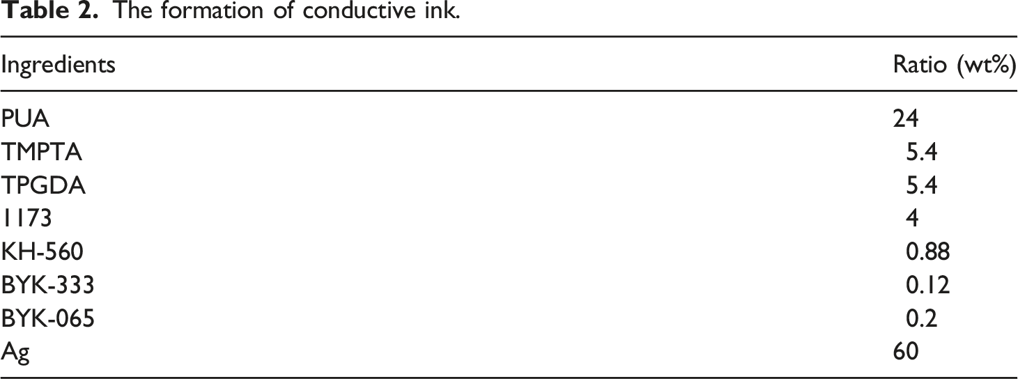
The formation of conductive ink.
Fabrication of textile-based UHF RFID tag antenna
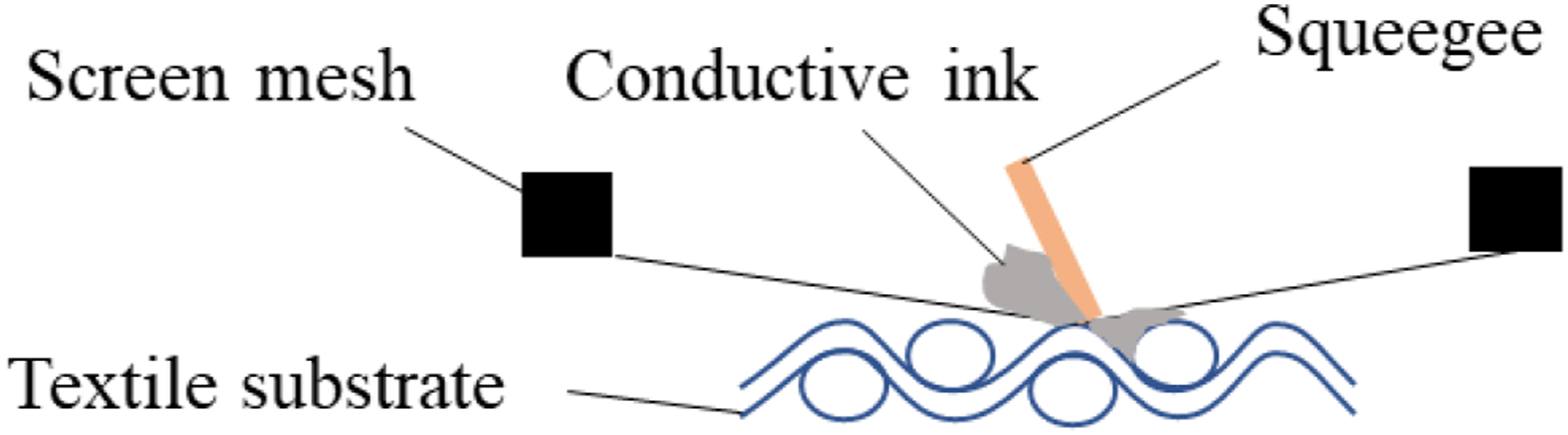
Firstly, the woven fabric was washed with ethanol, then rinsed in deionized water for 15 min, and dried in oven at 60°C. Finally, the cleaned fabric is used as the substrate for screen printed antenna. A desktop screen printer (China Kaimao Machinery Equipment Factory) was used to fabricate textile-based UHF RFID tag antennas. The structure and prototype of the printed tag antenna are shown in Figure 2, and the specific structure parameters are shown in Table 3. The principle of screen printing is shown in Figure 3. Pour ink on one side of the screen printing plate, and then exert a certain pressure to scrape the ink to the other side with a scraper, thereby printing a pattern on the surface of the fabric.
27
The printing speed is 170 mm/s. The scraper forms an angle of 85° with the screen. After the screen printing, the sample was cured in a UV curing oven for 40 s. Structure and prototype of UHF RFID tag antenna (a) UHF RFID tag antenna structure (b) Printed prototype of UHF RFID tag antenna on textiles. Structure parameters of UHF RFID tag antenna. Schematic diagram of screen printing.

Characterization and measurement
Fabric properties
In order to analyze the effect of the fabric surface structure on the quality of the printed antenna and its energy harvesting performance, fabric structure, wetting time, covering factor, and surface roughness as the main factors affecting the printing quality were characterized. For the dielectric properties of the fabric, the influence factor is porosity. The quality of the printed conductors was mainly evaluated in terms of their surface roughness, width, thickness, and electrical properties.
According to GB/T3820-1997 "Determination of Thickness of Textiles and Textile Products", YG141D-Ⅱ fabric thickness gauge was used to test the thickness of fabrics. Wetting time, when the droplet comes into contact with the fabric surface until it is completely absorbed, 28 of the fabric was tested by JY-PHb contact angle tester according to DB44/T 1872-2016 "Determination of surface wettability of textiles by contact angle method". The covering factor, which is also called as fabric compactness, is the percentage of the area covered by fiber or yarn under parallel light projection in the projected area of fabric. Woven fabric porosity refers to the ratio of the pore volume to the total volume in the fabric. 29 According to ISO 4288 standard, Wyko NT9100 optical profiler was used to measure the roughness of fabrics and printed conductors on its surface, and the contour arithmetic average deviation Ra was fabric surface roughness.
Regarding the printed conductor, the width of the printed conductor was measured by the Nikon SMZ745T stereo microscope. Considering that the edge of the printed conductor may be zigzag, the widest and narrowest points were measured during the test and calculated their average value. The JCM-6000Plus desktop scanning electron microscope was used to observe the cross-sectional morphology of the antenna conductive layer.
Electrical properties
The HPS2526 resistance tester was used to directly measure the square resistance of the antenna conductor. All tests were repeated for five times.
The antenna impedance was tested by the IM7585 impedance analyzer. Taking into account the power capacity and loss, the characteristic impedance of the antenna system transmission line is usually designed to be 50 Ω or 75 Ω. To maximize power transfer, the input impedance of the antenna connected to the high-frequency circuit should be designed to match conjugately with the characteristic impedance of the high-frequency circuit. 11 The voltage standing wave ratio (VSWR), calculated by the antenna impedance and the characteristic impedance, is usually used to reflect the size of the port standing wave. When VSWR is equal to 1, the antenna can reach the best impedance matching. 30
According to previous work, 31 the S parameters of the antenna was tested by the E5071C RF network analyzer, and the resonant frequency of the antenna was extracted to characterize the feasible working frequency band of the antenna.
For the antenna energy harvesting performance, the Powercast development board was used to test the maximum transmission distance under the main polarization direction of the antenna and the RSSI under a certain transmission distance. The antenna and Powercast development board were connected by SMA connector. By changing the distance between the UHF RFID tag antenna and the transmitter, the output RSSI value and the maximum transmission distance in the main polarization direction were recorded.
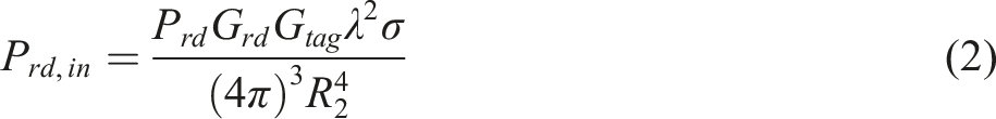
During the energy harvesting process of the UHF RFID tag antenna, the energy received by the tag antenna from the reader is expressed as RSSI and output voltage test schematic diagram.

Results and discussion
Influence of fabric structure on the quality and electrical property of printed conductors
Influence of fabric structure on the quality of printed conductor
The optical microscope images of antenna conductors printed on three fabrics are shown in Figure 5. It can be seen that the edges of the three fabric structures are not completely smooth. In addition to the rheological property of the ink, the non-smooth edges of the printed conductors are caused by the unique texture feature of the fabric surface, which facilitates ink to diffuse and penetrate non-uniformly on the fabric surface. Besides, the edge sharpness of the printed conductor is observed to be inversely proportioned to the float length. Generally speaking, the texture feature and holes of the fabric will affect the penetration and diffusion of the ink during the screen-printing process, thereby the thickness uniformity and even the continuousness of the conductive layer were affected and then make antenna’s radiation inefficient and transmission distance short.15,35 Optical microscope images of the antenna conductors on the surface of three fabrics (left: 1.5 times magnification; right: 4 times magnification). (a) 1#, (b) 2#, and (c) 3#.
In order to quantify the influence of the fabric surface characteristics on the surface morphology of the screen-printed antenna conductor, the printing accuracy is characterized by the percentage change, i.e.
As shown in Figures 6 and 7, screen-printed conductive lines are wider than designed. This deviation is caused by the unevenly spreading of conductive ink on fabric. In order to better observe the width deviation of the conductor, the printed width of 4 mm is selected as a comparison. Obviously, the printing accuracy of satin fabric is low and the conductor line width deviation printed on it is the largest, up to 0.9574 mm, while the twill fabric has the smallest line width deviation of 0.6092 mm. From Figure 6, it can be observed that the line width deviation of printed conductor is inversely proportional to the surface roughness and wetting time of fabric. The lower the surface roughness and the shorter the wetting time, the ink more easily spreads on the surface of fabric, thus increasing the deviation of the printed line width. And also, the multi-scale textures of the fabric surface facilitate the spreading and diffusion of ink through the yarns, and it increases the line width deviation of the printed wire.
36
Moreover, the surface roughness of the fabric and its printed conductors have a conformal feature, so the printed conductor has similar roughness to fabric substrate. The larger the surface roughness is, the higher the resistance of the antenna conductive layer and the lower the antenna gain is. These will affect the energy harvesting performance of the antenna.37,38 Fabric characteristics and its effect on the printing accuracy: (a) Surface roughness of the fabric and its printed conductor and (b) wetting time of the fabric. The fabric covering factor and its relationship with the printing accuracy.

The fabric covering factor and its relationship with the printing accuracy is shown in Figure 7. It is reported that, with the increase of fabric holes, the line width deviation of printed conductors gradually decreases. 16 Whereas, the results in Figure 7 shows that the line width deviation of the conductor printed on plain fabric is larger than that on twill. This phenomenon is attributed to loose structure of plain weave, where the thread density was lower than two other structures. Its large loose structure increases the penetration of ink between yarns and the diffusion of ink along yarns, so the line width deviation of plain fabric is larger than that of twill fabric.
In summary, the fabric structure will affect the wetting time, covering factor and surface roughness of the fabric, and then affects the quality and accuracy of the printed conductors on the fabric surface.
Influence of fabric structure on the electrical resistance of antenna conductor
Square resistances of conductors printed on three fabrics are shown in Figure 8. It shows that the conductor printed on plain fabric has the smallest square resistance, 1.362 Ω/sq. The low square resistance is attributed to two aspects. Firstly, it can be observed from Figure 6 that the twill fabric and its printed conductor have highest surface roughness, and the rougher fabric surface leads to the larger square resistance of the conductor printed on it.
16
Here, the square resistance of the conductor printed on twill fabric is the largest, 2.406 Ω/sq. Secondly, as shown in Figure 5, of three fabrics, the plain fabric has a well edge sharpness, while the satin fabric has longer floating lines and low edge sharpness of the printed conductor. Therefore, the square resistance of the conductor is larger than that of the plain fabric. In summary, a tighter structure and a smoother surface can better control the diffusion and penetration of the ink, thereby improving the dimensional stability of the printed conductor. Square resistances of conductors printed on three fabrics.


Resistivity and theoretical skin depth of antenna conductor (860–960 MHz).


Cross-sectional SEM images of conductive layer on fabric. (a) 1#, (b) 2#, and (c) 3#.
Influence of fabric structure on antenna performance
Antenna impedance
Impedance value of three fabric-based antennas.

Antenna resonant frequency and bandwidth
The measurement results of resonant frequency of three antennas are depicted in Figure 10. From the results, it can be observed that the resonant frequency of three antennas is between 860 and 960 MHz, that is, all of three antennas meet the basic working requirements. In addition, the designed center frequency is 915 MHz, and the closer the resonant frequency of the antenna is to the center frequency, the better the antenna performance is. The resonant frequency of the antenna printed on plain fabric is at 906.3 MHz, and it is closest to the center frequency, whereas that on twill fabric is at 867.5 MHz. This result is consistent with the printing quality as well as the square resistance of the printed conductor. Performance of antennas printed on three fabrics: (a) Resonant frequency and (b) -10 dB bandwidth.
In addition, the bandwidth of three antennas is between 407 and 464 MHz, which is much higher than other studies.40,41 The wide antenna bandwidth means that the antenna can work in a wider frequency band. The difference in the bandwidth of three fabric-based antennas is attributed to different dielectric constants of fabric substrates, which related to fabric porosity. 42 For the used three fabric substrate, the porosities of plain, twill and satin fabrics are 43%, 75%, and 73% respectively. Therefore, plain fabric has the largest dielectric constant and the narrowest bandwidth. In addition, fabric thickness has a certain impact on the bandwidth, and the antenna on a thicker fabric has wider bandwidth. 43 Therefore, from Table 1 the satin fabric is the thickest and has the largest bandwidth.
Antenna energy harvesting performance
Maximum transmission distance
The maximum transmission distances of three fabric-based antennas under the main polarization direction are shown in Figure 11. The transmission distance of the antenna printed on plain fabric is the largest, up to 110 cm, and that of antenna printed on twill fabric is the shortest, only 69 cm. According to the real part of the impedance in Table 5, their relative size is: plain <satin <twill, i.e., herewith the change of transmission distance is negatively correlated with that of the real part of the impedance. The conductor loss is directly proportional to the conductor resistance, which represents the loss of electromagnetic energy in transmission.
43
It is radically attributed to the difference of the surface roughness and porosity of fabric. Results clearly indicated that porosity of fabric relative to other properties has more prominent effect on the antenna energy harvesting performance. The maximum transmission distance of tag antenna is inversely proportional to the porosity and roughness of fabric. Generally, to improve the transmission distance of the antenna, the antenna should have low resistance and smooth conductor surface, which can be achieved by printing on a fabric with small porosity and low roughness, so the energy loss was small. Maximum transmission distances of three fabric-based antennas and the basic fabric properties.
Output voltage
Among the three fabric-based antennas, the shortest transmission distance is 69 cm on twill fabric. Therefore, the distance between the transmitter and the tag antenna is controlled to be 69 cm during of the test of the output voltage.
The output voltage of the antenna printed on three fabrics is 3.003 mV, 2.530 mV and 2.686 mV, respectively. Observably, the output voltage of the antenna printed on plain fabric is the largest while the antenna on twill fabric is the smallest. The relative size of output voltages of three printed antennas at a distance of 69 cm is consistent with their maximum transmission distance. Moreover, the result of output voltage is related to the gain of antenna, which is mainly ascribed to the quality of printed conductor. It is known from Figure 6 that the surface roughness of twill fabric and the printed conductor are highest. The surface roughness of the fabric will increase the random scattering of electromagnetic waves, thereby increasing the resistance and reducing the antenna gain. 44 Therefore, the antenna printed on twill fabric has the smallest output voltage. Moreover, as shown in Figure 5, the conductor printed on plain fabric has best edge sharpness, while the satin fabric has longer floating lines and low edge sharpness of the printed conductor. Therefore, the output voltage of the antenna printed on plain fabric is the largest.
Furthermore, the performance of fabric-based antennas is compared with that of antenna on PCB substrate. The maximum transmission distance of the antenna printed on fabric and PCB substrate are 1.1 m and 3.3 m, respectively. The RSSI of three fabric-based antennas and PCB antenna per unit area are 0.1265 mW/cm2, 0.0470 mW/cm2, 0.1092 mW/cm2, 0.4854 mW/cm2 respectively and the output voltages are 0.3090 mV/cm2, 0.2603 mV/cm2, 0.2763 mV/cm2, 0.3234 mV/cm2 respectively. Apparently, the performance of the antenna on rigid PCB substrate is better than on fabrics, which is attributed to high evenness of PCB antenna. Nevertheless, the flexible fabrics are intrinsically more comfortable and softer than PCB substrate for wearable. In general, the fabric with smooth surface and low porosity should be designed to obtain highly efficient RF energy harvesting.
General discussion
The correlation of main factors affecting antenna performance.

Conclusions
In summary, from UHF RFID tag antennas screen-printed on three fabrics with different basic weave structures, this work demonstrated the feasibility of common fabric as UHF RFID tag antenna for energy harvesting, and explained the influence of fabric structure on the quality of antenna conductor and RF energy harvesting performance.
The results presented in this paper shows that among the plain, twill and satin fabrics, the transmission distance of plain fabric-based UHF RFID tag antenna is the largest, up to 110 cm and the RSSI value and voltage value at 69 cm are the largest, which are 1.23 mW and 3.003 mV respectively. Experiments show that the surface roughness of printed conductor and the dielectric properties of fabric, which related to fabric porosity, have a strong negative correlation with the antenna energy harvesting performance. In addition, although the wettability, covering factor of the fabric will cause width deviation of printing conductor, it is in the allowable range. The resonant frequency of the fabric antennas printed on three fabrics basically meets the frequency of the global UHF RFID system and the basic working requirements. In terms of antenna energy harvesting performance, the smooth fabric surface with small aperture is more beneficial to highly efficient energy harvesting.
Footnotes
Declaration of conflicting interests
The author(s) declared no potential conflicts of interest with respect to the research, authorship, and/or publication of this article.
Funding
The author(s) disclosed receipt of the following financial support for the research, authorship, and/or publication of this article: This study is supported by the Fundamental Research Funds for the Central Universities (2232021G-01) and Shanghai Natural Science Foundation (20ZR1400500).