
Abstract
Recently, advanced composite materials have been widely used in numerous applications due to their superior properties. However, their sensitivities to damages during impact loading event limits their usage. In this regards, the influence of yarn hybridisation on the mechanical and thermal performance of composite laminates have been studied using low velocity impact, compression after impact (CAI), flexural and thermal conductivity tests. Two types of composite laminates were manufactured using hybrid yarns (S-glass and polypropylene [PP]) and S-glass yarns through the combination of commingling and core-wrapping methods and converted to non-crimp cross-ply preforms for both laminates. C-scan tests and cross-section microscopy examinations were adopted to identify the damaged areas of impacted laminates and explain the damage failures, which occurred during impact loadings. Results revealed that the hybrid laminates displayed higher damage area reduction compared to glass composites. Although the hybrid composite laminates illustrated considerably lower compressive strength, their residual compressive strength (damage tolerance) was significantly higher than glass composites. Fractography analysis has illustrated that the new damage failure modes such as intra-yarn cracks have been observed in the hybrid yarns laminates. These damage modes have contributed for higher energy absorpsion leading to an enhancement of the damage tolerance of the hybrid laminates. Furthermore, the incorporation of PP fibres resulted in a reduction of thermal conductivity of hybrid laminates compared to pure glass laminates.
Keywords
Introduction
Composite materials are widely used in different applications due to their excellent properties such as lightness, flexibility, durability, low cost in the production processes and diversity.1–3 In general, these materials are made from at least two different constituent materials, namely reinforcement and matrix elements which have different properties from each other.4,5 The appropriate physical properties such as lightness, elasticity, heat and electrical conductivity, economy, etc. of the composite laminates can be satisfied by selecting a suitable reinforcement element.3,6 Meanwhile, the properties such as the interaction of additive materials (i.e. particles) with matrix, binding, appearance, compliance with ambient conditions, ensuring load and voltage transformation, and impact protection are determined by matrix material. 7 Composites laminates are more complicated when they are subjected or loaded in the out-of-plane direction owing to the diversity in their components properties, resulting in significant damages such as matrix cracks, fiber breakage or delamination.8–10 These damages are responsible for a considerable reduction in the mechanical properties of composite laminates (i.e. compressive and flexural strengths) and structural integrity. 11 In order to ensure that impact induced composites do not catastrophically fail during service life and maintain maximum structural efficiency, the manufacturers and designers give significant attention to the post-impact properties such as compressive and flexural properties of composite laminates.12–14 Hence, it is important to understand their ability to continue functioning properly after damage events by evaluating their residual strength either compressive or flexural strength after impact tests.15–18
Many investigations have demonstrated that the damage tolerance of composite laminates can be improved by adopting different strategies. One of the promising strategies is toughening of the polymer matrix by tuning the polymer chemistry or by incorporating different particles like rubbers, thermoplastics or nano-scale particles. 19 In this strategy, the enhancement of matrix’s toughness has a beneficial effect on the matrix-dominated composite properties.20–22 However, the heterogeneous distribution of nano-particles and high viscosity of nano-modified resins are considered drawbacks of matrix hybridisation systems.23,24 Although high strength fibre composites (i.e. glass fibre composites) appeared higher strength performance (high tensile and compression strengths), their sensitive to impact loading has been considered a key issue during application. So that, using thermoplastic increases toughness of laminates which are manufactured with brittle resins and synthesis fibre, is a promising way for enhance damage tolerance of composite laminates.25,26 Hybrid composites can be classified into various types according to the numbers and distrubition of fibres through them. First types is known the interlaminated hybrids, where multi layers are combined together. Second type defined as the intra-ply or intra-yarn hybrids, where various types of yarns are mixed together in one layer. The final type called as intermingled hybrids, where the many fibres are commingled randomly in the composite laminates.27–30
Research works on the fibre hybridisation by combining two fibre types in unique composite have been shown as a promising approach for improving the impact performance of laminates. 31 Further researches have been focused on the combination of natural fibre with synthesis fibres such as glass fibre for enhancing the mechanical performance of composite laminates i.e. tensile, flexural, impact, and compression strengths.32–34 Compression and flexural strengths after impact have drawn attention from many researchers to evaluate the damage tolerance of composite laminates.18,35–37
Furthermore, in recent years, the composite laminates have been used as thermal resistance and insulation shells to retard the heat flow and maintain temperature of various devices at constant range.38–40 The thermal load of the fibre-reinforced composites can deteriorate the mechanical properties. When the composite laminate is exposed directly to the flame, the side of this compound adjacent to the fire, is the first area to be destroyed by fire, and subsequently the heat conduction and heat diffusion happen. 41 This might be explained by the fact that the distribution of heat inside these laminates produced local stresses, and many failure mechanisms have been occurred in composite laminates when subjected to various high temperature ranges resulting in micro-cracks.42,43 Hence, thermal conductivity is considered as a key factor for obtaining a specific design-requirement for composite laminates for aerospace applications and methods to predict the accurate thermal conductivity of composite laminates have taken considerable attention. 44 But only scant literature is available on thermal conductivity of composites laminates42,45–52 and to our best knowledge no measurement has been reported so far on the thermal conductivity of hybrid yarns composite laminates. In this work, we therefore assess the effect of yarn hybridisation on the flexural strength, impact response and post-impact compressive strength of composites as well as thermal condutivity. While a variety of products of the yarn hybridisation have been suggested in the literature, in this paper we used non-crimp preform made from hybrid yarns and glass yarns to produce the composite laminates. Scanning electron microscopy (SEM) has been utilised to investigate the damage failures of the impacted samples. Furthermore, the effect of yarns-hybridisation on the thermal conductivity of laminates has been assessed in this study.
Experimental details
Materials and composites manufacturing process
In this work, commingling and core-wrapping processes have been utilised to manufacture hybrid yarns. The hybrid yarns were made by the combination of two types of continuous fibres as shown in Figure 1. These fibres were a high strength S-glass fibre, and a high ductile Polypropylene (PP) thermoplastic fibre, which are supplied from AGY industries UK,
53
and Drake Extrusion UK
54
respectively. The details of the manufacturing process of hybrid yarns can be seen in ref. 12. The hybrid yarns were manufactured by combination of 15 S-glass yarns and 6 PP yarns through an air-jet nozzle; and subsequently, the hybrid yarns were wrapped with an additional PP yarn in a twisting machine (Direct Twist, Agteks, Turkey) resulting in a core wrapped hybrid yarn with 636 tex. For comparison purposes, 18 yarns from S-glass yarn (33 tex) were also combined together in order to manufacture S-glass yarns that have 624 tex linear density. The specification and physical properties of yarns are presented in Table 1. Schematic of the hybridisation of yarns process. Specifications of S-glass, PP, twisted S-glass and hybrid S-glass/PP yarns.

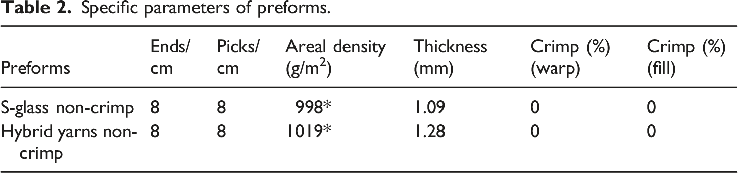
In this study, the non-crimp cross ply preforms, which were made from hybrid and S-glass yarns, have been used to manufacture composite laminates. All preforms were manufactured with the help of a pin-board frame (as seen in Figure 2). The specifications of the preforms are given in Table 2. Pin-board frame (a), and non-crimp cross ply preform (b). Specific parameters of preforms.
Properties of composite laminates.

The schematic and SEM micrographs of the microstructures of both types of laminates are presented in Figure 3. In general, both types of specimens have two kinds of layers: warp and weft layers, which are practically straight. However, the thickness of layers in the UD-HF specimen is slightly higher due to the PP filaments, which have thicker diameters (d = 27 µm) than the glass filaments (d = 9 µm). The cross-sectional shape of yarns in the weft direction is mostly lenticular and there are no resin–rich regions between plies. The schematic and SEM images of micro-structure of the laminates: (a) non-crimp twisted S-glass (UD-GF), (b) non-crimp hybrid yarns (UD-HF).
Test methods
Low-velocity impact Tests
Four impact energy levels (15, 25, 35, and 50 J) were used to investigate the influence of yarn hybridisation on the impact response of the composite laminates. CEAST 9350 drop-weight impact test machine was adopted for low-velocity impact tests (as seen in Figure 4). This machine has a 35 kN impactor force while the mass and diameter of the impactor are 5.028 kg and 20 mm respectively. Table 3 shows the dimensions of the composite samples, which were used in the low-velocity impact tests. Following Pichard and Hogg’s protocol for impact and compression after impact (CAI) tests, the composite specimens were cut to dimensions of 89 mm × 55 mm as length and width respectively.
55
Set up is showing drop weight impact test and composite specimen.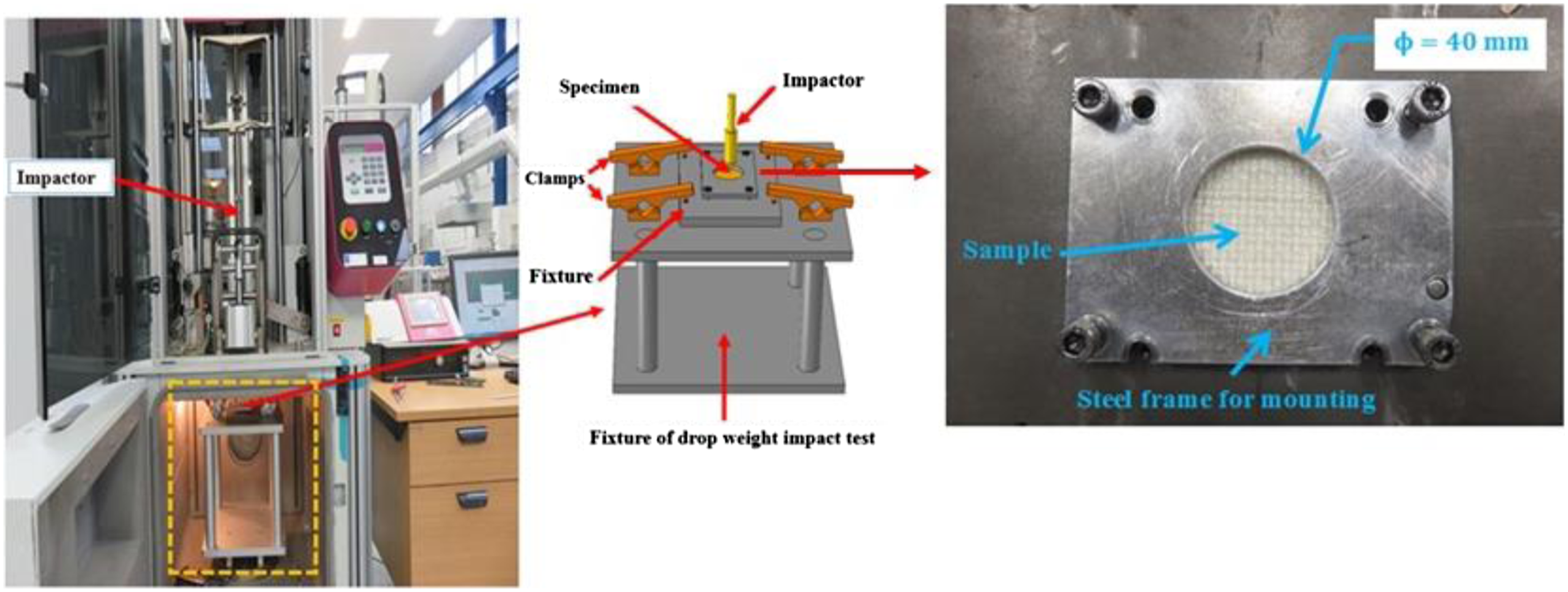
Compression after impact tests
Post-impact compression tests were adopted to evaluate the damage tolerance of the composite laminates. These tests are widely used due to the fact that composite laminates experience a great reduction in compressive strength even if the impact load is insufficient to produce visible damage. Therefore, the residual strength is measured for composite laminates after impact using the compression strength before and after–impact (CAI) tests. Instron testing machine model 5989 was used during the tests with a constant displacement rate of 0.5 mm/min. The sample edges were supported by the fixture in three sides to prevent buckling as illustrated in Figure 5. Four specimens were tested for each type of configuration. Composite sample under compression strength test.
Flexural strength test
In this study, The flexural strength properties of the laminates were evaluated using a three-point bending test according to BS EN ISO 14,125 standard.
56
The measurement was performed on an Instron testing machine model 5569 as illustrated in Figure 6 using a 5 kN load cell at a constant cross-head displacement of 1.0 mm/min. The dimensions of testing specimens (i.e. the support span length (l), width (b), and total length of specimen (L)) were chosen as a function of thickness (d) of specimens. The dimensions for tested specimens are displayed in Table 4. The flexural stress and modulus were measured using the following equations: Composite specimen under three-point bending test. Dimensions of composite specimens under three-points bending tests.


Thermal conductivity tests
The thermal conductivity (K) of composite samples was measured using Lee’s disc apparatus type Griffin and George as shown in Figure 7. This instrument consists of three discs of brass (A, B, and C) and a heater. The heater was switched on from power supply with 6 V and 0.2 A to generate the heat that was transferred to the next two discs (A and B) then to the third disc (C) across the composite sample. The temperatures of the three discs (TA, TB, TC) were measured by using thermometers. Lee’s Discs apparatus for thermal conductivity measurement.
In the beginning, the increase in the temperatures of the all disks was nonlinear with different rates versus the time according to its position from the heat source. After 45 min, the steady state of energy was obtained where temperatures of all discs reached to equilibrium. Therefore, the input energy became equivalent to output energy according to the following relationship:

Where The dimension of (a) UD-GF and (b) UD-HF composite samples for thermal conductivity test.

Analytical model for prediction the effective thermal conductivity
Several researchers have proposed theoretical and empirical models to estimate and predict the effective thermal conductivities of fiber reinforced polymer composites.44,57–61 In addition, comprehensive review articles have discussed the pertinent applicability of many of these analytical models. Most of these models have taken a two-component composite system according to the arrangement of materials in either parallel or transverse directions with respect to heat flow, which gives the upper or lower bounds of effective thermal conductivity.
For parallel conduction, the thermal conductivity is expressed by the following equation:
62

While the thermal conductivity in the transverse direction is defined by the following equation:
62

The correlations represented by equations (6) and (7) are derived based on the rules of the mixture. The effective thermal conductivity of composite laminates is given from the following equation:62,63
Characterisation of microstructure of laminates
In order to study the microstructure, failure modes of impact loading and damage failures during the flexural strength tests, the slices from composite laminates were cut using an abrasive cutting wheel and then coated by a thin coating layer. A microscope Philips XL 30 FEG was adopted to examine these composite slices.
Results and discussion
Analysis of impact resistance of composite laminates
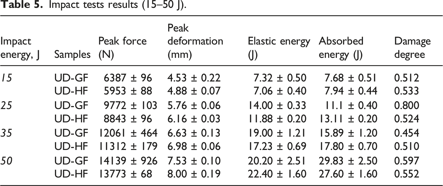
Impact tests results (15–50 J).
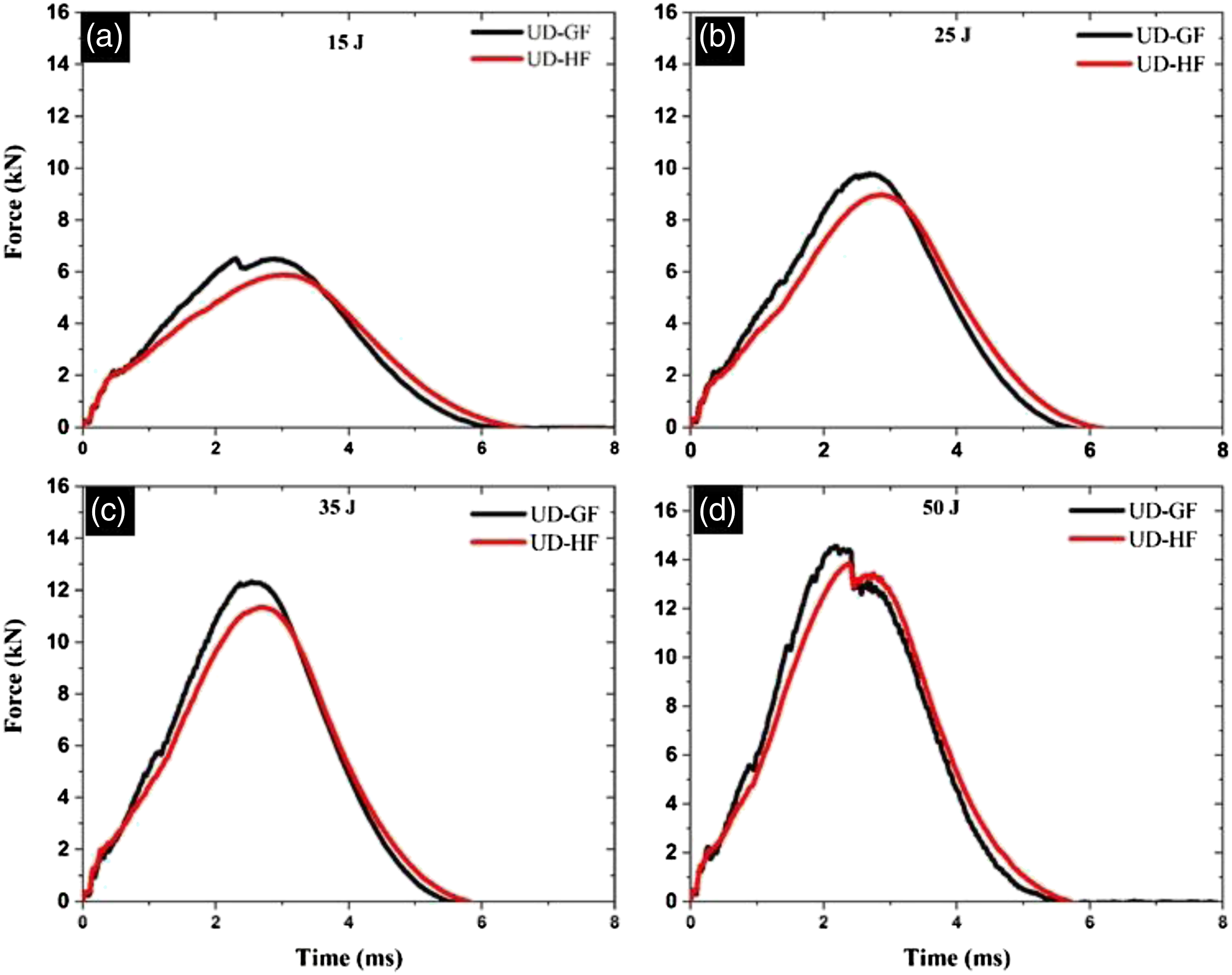
Force-time curves of impacted samples at (a) 15 J, (b) 25J, (c) 35J and (d) 50 J impact energy levels.

Force-displacement plots of impacted samples at (a) 15 J, (b) 25J, (c) 35J and (d) 50 J impact energy levels.

Impact energy history of impacted samples.

Energy versus time of impacted samples at (a) 15 J, (b) 25J, (c) 35J and (d) 50 J impact energy levels.

Damage areas versus impact energies of composite laminates.
Moreover, the UD-GF samples present two peak loads, the former at around 2 kN which represents the first sudden drop load that usually corresponds to the point at which delamination occurs. 64 The latter, which is equal to the maximum contact force, represents the end of matrix crack initiation and starting major damage. 65 Meanwhile, comparing the responses of the UD-HF, no sudden variations were observed in the slope of the hybrid laminate response curves. Due to the influence of yarn-level hybridisation (i.e. PP fibres), a sudden reduction occurs in the slope of the force-time or force-displacement curve which indicates unstable damage (e.g. delamination).
The load versus displacement response of represented samples at 15 J, 25 J, 35J and 50 J is also depicted in Figure 10. The qualitative damage, as well as the stiffness behaviour of impacted laminates is shown in the plots. Generally, the slope of load-displacement curves increase with increasing impact energy and a significant difference between hybrid composite and UD-GF samples can be noticed. One outstanding difference is that the stiffness is influenced by the distribution of the thermoplastic toughening agent in the matrix. It can be noticed that the UD-GF sample has S-glass fibres in both warp and weft directions without interlacement leading to higher stiffness compared to the UD-HF sample. This is because UD-HF sample has S-glass fibres mixed with PP fibres (ductile fibres) causing stiffness reduction in the hybrid composite laminates.
The impact energy is transferred from the impactor to the composite laminates based on the law of energy conservation through the impact loading. Figure 11 reveals that there is an increase in the energy until it reaches its peak value (Emax) and then drops to middle value (Ea). The middle value of impact energy, which is known as absorbed energy, is considered the main energy consumed to produce the damage failures in the laminates. The variation between the maximum value of impact energy (Emax) and the middle value of impact energy (Ea) is known as residual or rebound energy ER. 66
Figure 12 reveals the relationship between the impact energy (15 J–50 J) and time for all composite samples. Based on the curves, the content of PP fibres have a significant effect on elastic and absorbing energy. Compare to UD-GF, the hybrid composite presents an improvement in the total absorbing energy for all impact energies because more impact energy is consumed to create a PP/epoxy debonding. To stop penetration of the impactor, PP fibers combined with glass fibres in the UD-HF laminates leads to dissipation of kinetic energy by creating inter and intra-yarn cracks and these new types of damage failures. The contact duration between the impactor with laminates has increased by these cracks and therefore leads to the higher impact energy dissipation.
Damage area analysis
After impact testing, specimens were examined with an ultrasonic C-scan test to establish a correlation between the impact energy and impact resistance of composite laminates. Generally, in layered composites, the delamination occurs between layers which hides deep inside the laminate during the impact events. They can usually be observed by simple visible inspection. Thus, the ultrasonic C-scan is ideal for the impacted specimen inspection, providing a suitable image of the delamination areas through the composite thickness. Thus, for comparison, the damage areas versus impact energy with different levels are given in Figure 13. Two important observations are illustrated; firstly, for all specimens, the damaged area increases with increasing impact energy levels. Secondly, the hybrid composite laminates present lower damage areas compared to UD-GF samples. This may be attributed to clearer planes of lamination in UD-GF, which provide less resistance to the development and subsequent propagation of cracks. The presence of commingled PP and glass fibre together in the UD-HF laminates could create micro-damage failures such as intra- and inter-yarns cracks while they avoid damage propagation which results in damage area reduction.
Impact damage failures analysis
The microstructural analysis were conducted for the samples using SEM at the impact energy of 35 J to study the damage failures, as shown in Figure 14. As presented in Figure 14(a), different fracture mechanisms are observed in impact-induced UD-GF laminates. These fracture mechanisms are caused by transverse matrix cracks located below the contact point and with the shear fracture of fibre. Then, in-plane fracture or delamination is produced due to the cracks propagating to piles of different orientations and its size increases with an increase in distance from the contact area. Choi and Chang
67
confirmed that the damage failures in the cross-ply composites are mainly due to delamination and matrix cracks. Figure 14(b) shows the failure modes of UD-HF laminates. A significant reduction appeared in the delamination through the transverse micro-cracks introduced within hybrid yarns as shown in Figure 15. This is due to the yarn-level hybridisation which incorporates the commodity PP fibres through commingling and core-wrapping processes, with poor fiber-matrix interface properties. Images of cross-section of impacted samples at 35 J: (a) UD-GF and (b) UD-HF composite samples. The SEM images of damage failure modes obtained from UD-HF laminates.

Compression after impact analysis
The composite laminates without and with impact damage are subjected to compression strength tests to assess their residual compressive strength. The stress-extension plots of composite samples are compared for each impact energy level (i.e. 0, 15, 25, 35 and 50 J) and are presented in Figure 16. It can be noticed from Figure 16(a) that the compressive strength for UD-GF laminate is ∼275 MPa without impact. When compared with the post-impact compressive behaviour, a significant reduction (∼58–72%) in the laminate compressive strength is seen (ranging between ∼75 to 115 MPa) with varying impact damage energies (i.e. 15–50 J impact energies). The influence of compressive strength by yarn-level hybridisation can be observed in Figure 16(b), the compressive stress-extension behaviour is shown for the UD-HF laminates and the laminate compressive strength is ∼110 MPa without impact. When compared with the post-impact compressive behaviour, a reduction of ∼36–54% in the laminate compressive strength is seen (ranging between ∼50 to 70 MPa) with varying impact energies (i.e. 15–50 J impact energies). Higher residual strength values were also obtained by Selver and Potluri for hybrid composites due to smaller impact induced areas at different energy levels
68
Compressive stress versus extension for (a) UD-GF and (b) UD-HF lamiantes samples impacted at 0J, 15 J, 25 J, 35 J and 50 J energies.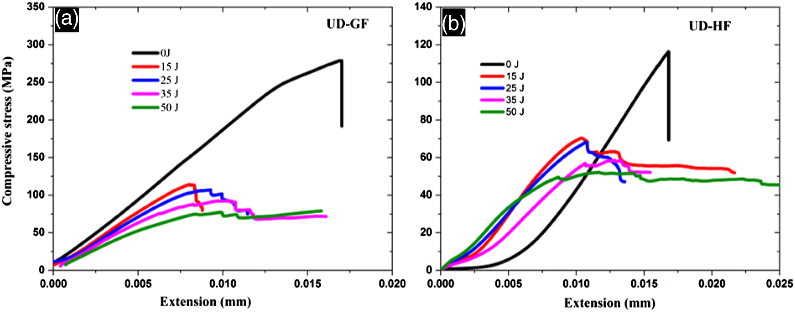
In general due to the yarn-level hybridisation, a significant reduction occurs in the compressive strength of S- glass composite laminates due to reduced content of the S-glass fibre volume while a significant improvement in the post-impact compressive strength is achieved. Figure 17 shows the relationship between the residual compressive strength and the impact energies. It can be seen that the UD-GF has lowest residual compressive strength when compared to the UD-HF laminates. These results are expected from the damaged areas versus impact energies as illustrated in Figure 13. This shows that damages due to matrix cracks, delamination and fibre fractures in UD–GF can cause a higher reduction in CAI strength. The strength of the hybrid composite laminates is still higher due to the local damaged areas during the impact events. Dost et al.
69
confirmed that the tensile and compressive residual strength can be affected through the load distribution which results from the damage dominated by fibre failure. Nejhad et al.
70
noticed that the residual compressive strength was significantly reduced through the larger damage area induced in the carbon/PPS composites during the impact loading. Besides, they found that residual compressive strength was slightly decreased through the smaller damage area. The residual compressive strength (%) with varying impact energies for the UD-GF and UD-HF composite laminates.
In order to investigate the failure patterns that occur in the non-impacted and impacted samples subjected to compression strength test, photografic images are presented in Figure 18. For non-impacted specimens, the typical failure patterns occur in the UD-GF laminate are delaminations with possible several delaminations at the different interfaces. Damage visualization of compressive before and after impact loading (35 J) for (a) UD-GF and (b) UD-HF.
A vertical and a major horizontal matrix cracks are also observed in the middle of specimens. On the contrary, the hybrid composite sample illustrated horizontal matrix cracks, which are initiated in the centre of the samples and further propagated to the edges. The damage profile of compression loading after subjecting to impact (35J) for both type of samples are presented in Figure 18. Local buckling of the sub-laminates, which is originating in the impact area, causes the failures of impacted UD-GF laminates under uniaxial compressive loading. Delamination has propagated mainly perpendicular to the applying loading, while it is smaller in 0° direction and results in reduction of the bending stiffness of impacted UD-GF lamiantes. Therefore, they buckle locally and failure happens at lower loads than non-impacted samples. The impacted hybrid laminates specimens show buckling shape at the damaged areas and the cracks initiate at the impacted region, and progresses in a transverse direction to compressive loading with very little or no damage growth in the loading direction.
Flexural strength tests results
Typical flexural stress-deflection curves for both types of laminates are presented in Figure 19 and Table 6. As expected, the UD-GF laminate has the highest flexural strength and lowest deflection compared to the UD-HF as shown in Figure 19. However, both specimens show nearly fragile behaviour with a non-linear region only at the end of the tests and a sudden drop of the stress after peak stress is recorded. The zigzag aspect of the stress-deflection curve for the UD-GF and UD-HF specimens indicates the existence of different damage mechanisms (e.g. delamination). Flexural stress-deflection of UD-GF and UD -HF laminates. Flexural properties of all laminates.

Figure 20 presents the average values of flexural stress and flexural modulus of laminates. It can be noticed that flexural stress and flexural modulus of UD-GF are about 99% and 71% higher than UD-HF, respectively. The reduction of flexural properties of hybrid composite laminate can be attributed to the higher elongation and lower strength of PP fibres which are commingled with glass fibre in the UD-HF specimens. Ömer Yavuz Bozkurt
71
showed that using of basalt fibers for partial substitution of aramid fibers in the composite laminate could provide enhancement in the tensile and flexural properties. Ultimate flexural strength (a) and flexural modulus (b) of UD-GF and UD-HF composite laminates.
Figure 21 shows the micrographs of the three-points bending failures of composite laminates. Scanning electron microscopy observations show that the UD-GF laminates fail catastrophically and the tensile fracture of fibres is clearly seen in the bottom layer. While the observation of upper layers shows the interface failures of fibre-matrix such as debonding, delamination, and fibre crushing, as shown in Figure 21(a). In contrast, Figure 21(b) presents delamination and matrix cracks in the bottom layers of the UD-HF laminate results in a better resistance to fibre failures. This overall improvement in the microstructure of the hybrid lamiantes has a very positive influence on the mechanical performance, and it is believed to be one of the major reasons behind the positive hybridisation effect. In addition, the brittle and catastrophic failure modes, which observed in by glass lamiantes, can be avoided by the hybridisation of glass fibres with PP fibres. Thus, the presence of glass fibres (that exhibit a very strong fibre matrix interface) in the hybrid composites significantly increase the flexural strength of hybrid specimens, whereas the foundation of PP fibres increases the elongation of the hybrid lamiantes compared to the glass laminate specimens, as observed in flexural test results. SEM images of damage failures of lamiantes under three-points bending test: (a) UD-GF, and (b) UD-HF.
Thermal conductivity analysis
The comparison of effective thermal conductivity obtained from proposed model and experimental results for both types of composite laminates (i.e. UD-GF and UD-HF laminates) are shown in Figure 22. It can be noticed that the glass laminates have an extremely higher thermal conductivity than the hybrid laminates. This is because the glass fibers are linked to make a network (as shown in Figure 23(a)) that play a role for increasing the heat flow transferring paths and allow temperature distributions easily inside the composite laminates. The low thermal conductivity of hybrid laminates could be due to the lower value of intrinsic thermal conductivity of PP fibres, which are aligned as a shell to prevent heat passing through thickness of hybrid composite laminates (as shown in Figure 23(b)). Further, it can be seen that the values obtained from the proposed model fit well with the experimental data. However, the values obtained from the proposed model are higher than the experimental data and this is because the theoretical model assumes that the longitudinal and transverse heat transfer unformally in composite laminates leading to higher values of thermal conductivity for the model compared to the experimental results. Thermal conductivity (experimental and theoretical) for (a) UD-GF and (b) UD-HF composite laminates. Heat transfer through composite laminates (a) UD-GF and (b) UD-HF composite laminates.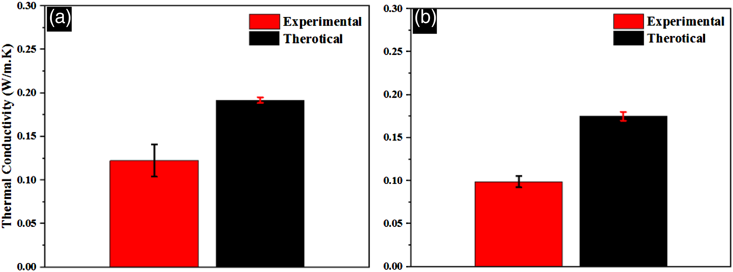

Conclusion
In this study, the influence of yarn level hybridisation on damage tolerance, mechanical performance as well as the thermal conductivity of composite laminates have been characterised. Hybrid yarns are produced by combining. S-glass and PP using both commingling and core-wrapping processes together. The non-crimp cross-ply composites were manufactured using those yarns via vacuum infusion process with epoxy resin. The mechanical performances were evaluated by flexural strength, impact, compression and CAI strength tests. Thermal conductivity of both glass and hybrid composites were also compared. In addition, the damage failures after the impact and CAI tests respectively are examined using SEM for identifying damage modes in the hybrid laminates. The following key conclusions can be drawn: • The ability of glass lamiantes to absorb impact energy can be improved by hybridisation (glass fibre with PP yarns). It was found that the absorbed energy in the hybrid yarns laminates enhanced around (3.20%, 15.34, and 11.00%) at (15–35 J) impact energy respectively, compared to the glass fibres laminates. • Scanning electron microscopy images presented that impact damage failures in the non-crimp glass laminates are mainly due to delamination and fibre fractures. While, the transverse matrix cracks, PP/epoxy debonding, and delamination with plastic deformation of PP fibre were observed in hybrid laminates. This is due to presence of PP fibres introduced intra-yarn cracks via PP fibres matrix debonding. • The yarn-level hybridisation significantly influenced the material strength and load-carrying capacity of hybrid lamiantes under quasi-static three-point bending loading. For instance, the flexural strength of the glass laminate is ∼50% higher than that of the hybrid laminates. However, the hybrid laminates exhibited gradual softening without catastrophic failures under three-points bending compared to the glass laminates due to various micro-scale intra-tow delamination occurring in the hybrid laminates and hence spreading the load over a wider area. • Incorporation of PP fibre with glass fibres have resulted in a reduction of thermal conductivity of hybrid composite laminates; these reduction were 10.5% experimentally and 11.8% theoretically and thereby improves its thermal insulation capability compared to the glass fibre laminates. The observed reduction in thermal conductivity of hybrid laminates may be due to the lower thermal conductivity of PP fibres, which prevented the heat transformation through laminates.
Footnotes
Declaration of conflicting interests
The author(s) declared no potential conflicts of interest with respect to the research, authorship, and/or publication of this article.
Funding
The author(s) received no financial support for the research, authorship, and/or publication of this article.