
Abstract
Though fiber reinforced thermoset composites exhibit excellent rigidity and strength while being lightweight, they suffer from low toughness and brittle failure, which is unfavorable. On the other hand, fiber reinforced thermoplastic composites are good energy absorbers, damage resistant and recyclable; however, these materials exhibits insufficient rigidity. As a solution, the interlayer hybridization of glass fiber reinforced thermoset (GTS) and glass fiber reinforced thermoplastic (GTP) composites is proposed. This study aims at investigating the tensile properties of interlayer hybrid thermoset-thermoplastic composites. In this regard, two non-hybrid and two hybrid composite samples (GTS2-GTP and GTS4-GTP) were fabricated using common fabrication techniques: hand lay-up and hot compression molding. Both hybrid composite samples were fabricated in such a manner that GTP was sandwiched between two GTS plates. Based on the tensile test results, the failure strain of GTS sample was improved due to the interlayer hybridization with GTP. Non-hybrid composite samples exhibited one load drop in their tensile stress-strain behavior, while interlayer hybrid composites showed two load drops, which resulted in toughness increment. Moreover, hybrid thermoset-thermoplastic composites outperformed non-hybrid composites in terms of post-impact tensile properties.
Introduction
Fiber reinforced composites have found broad applications in various industries such as automobile, transportation, aerospace, sports and medical1–3 due to their unique and interesting properties including high specific tensile strength and stiffness, good fatigue performance, lightweight, easy tuning properties and functionalities based on requirements.4,5 However, low toughness and failing in brittle manner (i.e., sudden catastrophic failure under external loading) have limited fiber reinforced thermoset composites. 6 Although they have highly acceptable tensile stiffness and strength, their toughness is an inevitable concern for designers. As a solution, it is offered to fabricate hybrid composites to enhance the energy absorption properties of composites. 7 In general, hybrid composite is referred to those composites made of various material types (i.e., fibers, nano/micro-sized particles, metals, matrices).8–10 For instance, hybrid composites can be formed through combining two or more fiber types in a single matrix, known as hybrid fiber composites. It is common to combine a low elongation fiber (i.e., carbon fiber) with a high elongation fiber (glass, Kevlar, etc.). Generally speaking, hybrid effect is referred to any positive deviation of mechanical property of fiber hybrid composites from predictions of rule of mixture.11–14 According to Swolfs et al., 8 hybrid effect is basically defined as the improved failure strain of low elongation fiber in hybrid composites in comparison to failure strain of low elongation fiber in non-hybrid composites. Modifying failure progression of low elongation fiber via hybridizing with high elongation fiber to gain a unique failure behavior, i.e., pseudo ductility, can also be regarded as hybrid effect.15–17
There are a considerable amount of research studies reporting the positive hybrid effect, i.e., improved failure strain of low failure strain components of hybrid composite; however, only a few of them will be addressed here.18–30 Hayashi, 18 as a pioneer in this discipline, observed 40% improvements of failure strain of carbon fibers when hybridized with glass fibers in comparison to non-hybrid carbon fiber reinforced composite. Following Hayashi reports, similar finding was also observed by other researchers dealing with hybrid carbon/glass composites19–23 during 1970s and 1980s. Qiu and Schwartz 21 noticed improved failure strain of Kevlar-149 fibers in hybrid Kevlar-S glass composites, though lower tensile strength was achieved in comparison to non-hybrid composites. Later, You et al. 24 discerned improvements in failure strain of carbon fibers in hybrid glass/carbon composites while assessing the tensile properties of fiber reinforced composite rods. They achieved 3%–33% enhancement of failure strain, which is dependent on the degree of dispersion of both fibers. Subagia and Kim 25 assessed the tensile response of hybrid carbon-basalt/epoxy composites. Their results showed that hybrid carbon-basalt composites had higher failure strain but lower tensile strength than non-hybrid carbon/epoxy composites. Recently, Sung et al. 26 witnessed enhanced failure strain of carbon fiber reinforced composites when interlayer hybridized with a sheet of steel; however, this synergy effect was left unnoticed in other hybrid fiber-metal laminate publications.27–29 In the category of hybrid fiber composites, several hybrid mechanisms leading to the enhancement of failure strain of low elongation fibers were discussed in-detail in Ref. 8. To sum, thermally induced stresses on fibers, modifying the damage development and also reducing the stress concentrations were mentioned as major hybrid mechanisms in fiber hybrid composites. Besides, Sung et al.26,30 addressed another hybrid mechanism which is resulted from the Poisson’s ratio mismatch of carbon fiber reinforced composite and steel laminas.
As another class of hybrid composites, thermoset and thermoplastic matrices are also combined in a single composite structure.31–34 Fiber reinforced thermoset composites offer higher rigidity than fiber reinforced thermoplastic composites, while the latter outperforms the fiber reinforced thermoset composites in terms of toughness and damage threshold.35,36 Attempts were made by researchers to benefit from both thermoset and thermoplastic matrices in a composite part.37–40 In this respect, a review study was conveyed by Nash et al. 40 regarding the effect of incorporating a thermoplastic phase in fiber reinforced thermoset composite to improves its damage threshold. However there are few studies assessing the performance of interlayer hybrid thermoset-thermoplastic composites. Boria et al. 33 evaluated the crushing behavior of interlayer hybrid thermoset-thermoplastic composite under impact loading and compared it with non-hybrid composites. They used carbon/epoxy composite as thermoset lamina and self-reinforced polypropylene as thermoplastic lamina. Mechanical properties of interlayer hybrid thermoset-thermoplastic composite was assessed experimentally by Chitturi et al. 34 Glass/epoxy and polycarbonate sheet were used respectively as thermoset and thermoplastic components of the hybrid composite. Their results showed the enhancement of failure strain of glass/epoxy composite when hybridized with a thermoplastic composite; however, it was left unnoticed. Bauer et al. 37 improved the interfacial strength of hybrid thermoset-thermoplastic composites (carbon/epoxy and short glass/polyamide) using low-pressure plasma. Three different surface treatment techniques (surface silanization, CO2 laser ablation and plasma treatment) were adopted by Ding et al. 41 to assess the interface properties of hybrid thermoset-thermoplastic composites. Based on their results, CO2 laser ablation technique yielded highest interface strength in comparison to other techniques. UV irradiation treatment of thermoplastic matrix was found as an effective approach to improve interface strength of hybrid thermoset-thermoplastic composite. 42
The main goal of this research is to conduct an experimental investigation on the effect of interlayer hybridizing glass fiber reinforced thermoset (GTS) composites with glass fiber reinforced thermoplastic (GTP). Several purposes can be sought from this type of hybridization. First, modifying the failure progression of GTS composites from a sudden failure to a more controlled and progressive failure manner, i.e., tensile stress-strain diagram containing multiple load drop, not single. Second, improving the damage threshold of GTS composites. Third, mitigating the induced static and dynamic stress concentration from failed GTS laminas within the GTS laminates. However, this study focuses only on the effect of this type of hybridization (i.e. interlayer) on the tensile and also post-impact tensile responses of hybrid GTS-GTP composites. In this regard, two non-hybrid GTS and GTP laminates, and two hybrid GTS-GTP laminates were fabricated. Uniaxial tensile tests were performed on undamaged and damaged composite sample in accordance with ASTM D3039. As expected, interesting findings were obtained and are discussed in the following. Findings of this study can be beneficiary for current automobile body parts that are made of fiber reinforced thermoset composites, since these materials exhibit low toughness due to their intrinsic brittle type of failure.
Materials and methods
General physical and mechanical properties of reinforcement and matrices.

Sample preparation processes
Simple and convenient fabrication techniques were selected to produce glass fiber reinforced thermoset and thermoplastic composites (GTS and GTP, respectively). For glass fiber reinforced thermoset composites, hand lay-up technique was chosen and hot compression molding method was selected for fabricating glass fiber reinforced thermoplastic composites. A brief description of each fabrication method is given in the following.
For producing glass fiber reinforced thermoset composites, at first surface of a rectangular glassy flat mold were polished with sufficient amount of release agent. Then, surface of the mold was coated with an appropriate amount unsaturated polyester resin. Afterwards, a woven E-glass layer was placed on the surface and was subsequently impregnated by polyester resin. This process is repeated until the desired thickness is reached. Finally, the whole assembly was held under pressure for 24 h at room temperature to allow the polyester resin to cure. Figure 1 illustrates the hand lay-up technique for fabricating GTS laminate. Schematics of hand lay-up technique for fabricating glass fiber reinforced thermoset plate.
On the other hand, for producing glass fiber reinforced thermoplastic composites, a layer with an appropriate thickness was achieved from melting the thermoplastic polyurethane (TPU) pellets. Then, glass fabrics were sandwiched between thermoplastic polyurethane layers and the whole assembly was fed into a hot compression molding machine. This must be mentioned that a pre-heating process was done on samples for 5 min at 195°C. Hot-compression molding was conducted at 195°C 8 min and cooling speed was about 2.5°C/min. An illustration of hot-compression molding approach for producing GTP laminate is depicted in Figure 2. Schematic of hot-compression molding technique for fabricating glass fiber reinforced thermoplastic plate.
Non-hybrid composite samples, i.e., GTS and GTP, were fabricated as described earlier, hand lay-up and hot compression molding techniques, respectively. To produce hybrid thermoset-thermoplastic composite samples, at first GTS and GTP composite plates were prepared separately. Then GTP lamina was sandwiched with two GTS laminates. Ultimately, the whole assembly was placed under hot compression molding. The pre-heating process was done for 2 min at 195°C and hot compression molding process was performed at 195°C for 5 min and cooling speed was about 2.5°C/min. Figure 3 presents a schematic of fabrication process of interlayer hybrid thermoset-thermoplastic composite. Schematic of fabrication process of interlayer hybrid thermoset-thermoplastic composite.
Two interlayer hybrid thermoset-thermoplastic composite samples were produced via the mentioned fabrication procedure (see Figure 3). Figure 4 illustrates schematically the fabricated non-hybrid and hybrid composite samples. One glass reinforced unsaturated polyester composite (GTS), one glass reinforced thermoplastic polyurethane composite (GTP) and two interlayer hybrid thermoset-thermoplastic composites were fabricated. In the proposed interlayer hybrid composites, GTP lamina is sandwiched by two GTS laminates with the aim of assessing the role of GTP lamina at modifying the failure development of GTS laminates. Besides, GTS laminates were used as external plies to provide more rigidity against out-of-plane loading (i.e. bending). Their general specifications are tabulated in Table 2. Fiber volume fraction of components (GTS and GTP) of interlayer hybrid composites were equal to non-hybrid GTS and GTP samples. Schematics of prepared non-hybrid and hybrid composite samples. General specifications of non-hybrid and hybrid composite samples. GTS: glass fiber reinforced thermoset; GTP: glass fiber reinforced thermoplastic; TPU: thermoplastic polyurethane.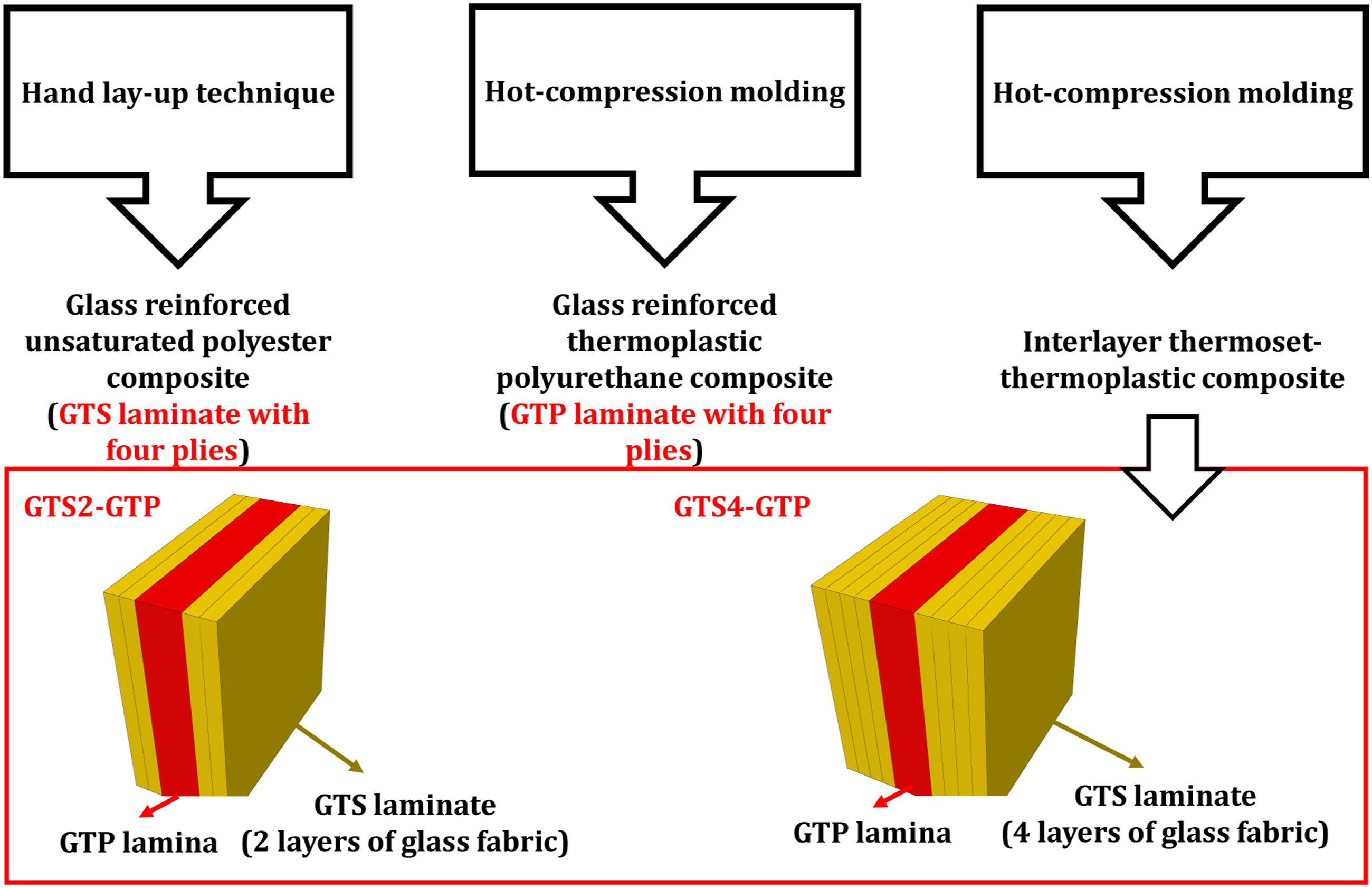

Determining fiber volume fraction
Fiber volume fraction of each GTS and GTP composites were determined using the instructions stated in ASTM D3171. Simply the matrix part of GTS and GTP composites were burnt off by placing a small piece of them in an oven. Recording the weight of the sample before and after ignition and also considering the density of each constituent, the fiber volume fraction of GTS and GTP composites were calculated. Knowing the volume fraction of GTS and GTP composites, the density of each composite lamina can be determined using rule of mixture. Then, the relative volume fraction of GTP in hybrid thermoset-thermoplastic composites were achieved using the following equation.

Assessing the tensile and post-impact tensile properties
Uniaxial tensile tests were performed on prepared composite samples in accordance with ASTM D3039, as shown in Figure 5. Thus, three specimens with appropriate dimensions (25 ×250 mm2) were cut from fabricated composite plates using water jet. Hounsfield universal testing machine equipped with 25 Hounsfield universal testing machine prior to performing tensile test on composite sample.
To fulfill one of the purposes of the current study, i.e., the effect of GTP layer at improving the damage threshold of hybrid thermoset-thermoplastic composites, a low energy impact event was simulated using drop weight impact testing machine, as schematically shown in Figure 6. Thus, an impactor with a hemispherical head and mass of 1.3 Kg was dropped from a specific height to exert a low energy impact on composite samples. Since composite samples have different thicknesses and it might affect their post-impact tensile properties, each sample was subjected to low energy impact event with different impact energy in proportion to their thicknesses. Based on the available literature on the Charpy impact properties of glass fiber reinforced thermoset composites, impact strengths of glass/thermoset composite lie in the range of 110–140 kJ/m2.43–46 Thus, attempts were made to apply an impact energy equal to a normalized value of 70 kJ/m2. Now the impact energy and subsequently the height of releasing the impactor can be determined for each non-hybrid and hybrid composite samples, since values of thickness (t) and width (w) are known. Schematic of falling weight impact test to induce damage on composite samples.

Results and discussion
Figure 7 shows tensile stress-strain diagrams of GTS, GTP, and GTS2-GTP and GTS4-GTP samples. It is noteworthy that the plotted tensile results are the mean of three specimens. GTS composite sample exhibited a linear elastic behavior up to failure, which is common for fiber reinforced thermoset composites. Failed GTS composite sample is shown graphically in Figure 7. According to ASTM D3039, its failure mode can be characterized as “AGM”, which means that the failure occurred in the middle of the gage length in an angled form. Each letter of term “AGM” refers to the type, area and location of failure. Thus, first character of “AGM” refers to the failure type, which was angled (A), second character refers to the failure area, which occurred within the gage length (G), and finally third character refers to the failure location, which was at the middle (M). Similarly, GTP composite showed linear elastic behavior up to failure as strain increases; however, with considerable lower slope than GTS composite. Similar failure mode to GTS was observed for GTP, i.e., “AGM”. Tensile test results of non-hybrid (GTS and GTP) and interlayer hybrid (GTS2-GTP and GTS4-GTP) composite samples. GTS: glass fiber reinforced thermoset; GTP: glass fiber reinforced thermoplastic.
According to the observed tensile responses of non-hybrid composite samples, it is expected from the hybrid composite samples to exhibit a tensile response which is a combination of both constituents. That is, the slope of the elastic region obeys the rule of mixture according to volume fraction of each constituent until the failure strain of GTS laminate. This must be mentioned that a progressive and controlled failure of GTS laminate is expected, since GTS laminates are held apart due to presence of GTP lamina. After failure of GTS laminates, only GTP lamina will resist against the applied load. Based on plotted stress-strain diagrams of hybrid samples in Figure 7, both interlayer hybrid composite samples showed similar tensile responses. Tensile responses of hybrid composites can be characterized in three regions. In the first region, marked as “a”, tensile stress increases linearly as strain increases, which its slope is as a function of Young’s modulus of both GTS and GTP. It must be mentioned that while performing tensile tests, numerous crack sounds were heard in the first region prior to the first load drop for a considerable range of strain. Apart from matrix cracking sounds, these long-term cracking sounds could be corresponded to the delamination initiation and propagation between GTS and GTP laminates. This claim cannot be stated with high certainty, since in-situ monitoring techniques such as acoustic emission registration or digital image correlation are required to identify damage mechanisms. 47 However, the occurrence of delamination is highly likely due to the presence of not quite strong interface bonding between GTP and GTS laminates, since no chemical or mechanical treatments were carried out on surfaces of GTS laminates to enhance the affinity. As expected, there are two load drops in the stress-strain responses of both hybrid samples in the second region (marked as “b”), each drop is attributed to the failure of GTS laminates. Failure of each GTS laminate is shown graphically in Figure 7 next to the each plotted tensile response of hybrid composites. Third region, marked as “c”, starts after second load drop and is characterized by a long plateau with a low constant stress level (around 15 MPa). Third region is formed due to the presence of GTP lamina, which is still almost intact. This region continues until the failure of GTP composite lamina. Tensile tests were aborted at the strain of 10% for hybrid composite material, since the remaining tensile responses of hybrid composites were unimportant. Failed hybrid composite samples were examined after tensile tests and complete delamination between GTS and GTP layers was observed for both samples.
As can be observed, unlike non-hybrid GTS composite samples, GTS composite laminates of hybrid samples failed at different locations. Since GTP layer was still intact after failure of both GTS laminates, it can be inferred that modification of failure progression of GTS laminate and controlling its adverse effect on each other in terms of induced static and dynamic stress concentration due to their failure were achieved. That is, due to the presence of GTP lamina between GTS laminates, damage initiation and progression in a GTS laminate had no interaction with other GTS laminate. Thus, each GTS layer will fail at its own failure strain (which is inconsistent and dependent on the formed defects during manufacturing), not triggered or caused by the failure of other GTS laminas. GTP layer within the GTS laminates is acting as a hindrance to the damage propagation in the thickness direction. Whenever the formed cracks within the GTS layers propagates in the thickness direction and reach the GTP layer, their path will be deviated and deflected along the interface of GTP and GTS layers and cause delamination. Long-term cracking sounds prior to failure during performing tensile tests, and complete delamination between GTP and GTS layers after tensile tests and also GTP being almost intact after failure of GTS laminates support the role of GTP as crack barrier in the thickness direction. Figure 8 illustrates the role of GTP lamina as crack barrier/deflector in the thickness direction. Illustration of failure development in GTS laminate and interlayer hybrid GTS-GTP laminate. GTS: glass fiber reinforced thermoset; GTP: glass fiber reinforced thermoplastic.
According to ASTM D3039, interlayer hybrid composite samples exhibited mixed-mode failure types. That is, failure modes of DGM, which is delamination (“D”) at the middle (“M”) of the gage length (“G”) of composite samples, and AGT and AGB, which are angled failure type (“A”) at the top (“T”) or bottom (“B”) of in the gage length (“G”), respectively.
A comparison between tensile stress-strain curves of non-hybrid and interlayer hybrid composite samples was made in Figure 9. Tensile properties were also calculated from the tensile test results and are tabulated in Table 3. Toughness values of hybrid thermoset-thermoplastic composites were calculated up to the strain of second failure of GTS lamina. As expected, stress-strain diagrams of hybrid thermoset-thermoplastic composite samples lied between those of non-hybrid composites. One may notice the reduced tensile strength and modulus of GTS composite when hybridized with GTP composite. This should be mentioned that the purpose of the proposed hybridization was not improving the tensile strength or Young’s modulus of GTS composites. However, relative volume fraction of GTP composite in the hybrid thermoset-thermoplastic composite can be tailored in such a way that have lower negative impact on the tensile strength and Young’s modulus of the final composite part. Skipping the tensile strength and Young’s modulus, hybrid thermoset-thermoplastic composite samples exhibited higher failure strain in comparison to non-hybrid thermoset composite sample. Considering the strain of second failure in hybrid thermoset-thermoplastic composites as ultimate failure strain, GTS2-GTP and GTS4-GTP composite samples failed at 6.4% and 8.2%, respectively, which are considerably higher than failure strain of non-hybrid GTS composite (which is 4.77%). This enhancement of failure strain could also lead to improving the toughness of composite sample. According to Table 3, GTS2-GTP composite exhibited lower toughness in comparison to GTS composite, while GTS4-GTP composite showed higher toughness than GTS composite. This implies the crucial role of tailoring the relative volume fraction of GTP lamina in hybrid thermoset-thermoplastic composites. Comparing the tensile responses of non-hybrid and hybrid composite samples. Tensile properties of non-hybrid and hybrid composite samples (values in parentheses are standard of variation). GTS: glass fiber reinforced thermoset; GTP: glass fiber reinforced thermoplastic. a

Based on the reported failure strain values in Table 3, GTS composite lamina failed at the strain of 4.77%. Therefore, it is highly expected that the first load drop in the tensile stress-strain response of hybrid thermoset-thermoplastic composites happens at the failure strain of GTS lamina (i.e., 4.77%), unless otherwise there is a hybrid effect. Through comparing the failure strain of GTS composite with the first failure strains ( Improved failure strain of glass fiber reinforced thermoset lamina when hybridized with glass fiber reinforced thermoplastic lamina.
As discussed in the introduction section, multiple purposes were pursued in this type of hybridization. Some of them, which was modifying the failure development and mitigating the adverse effect of induced stress concentrations, were discussed in detail earlier. In following, the role of GTP lamina at improving the damage threshold of GTS laminates will be discussed. As explained thoroughly in “Materials and Methods” section, each non-hybrid and hybrid composite samples were subjected to low energy impact in proportion to their thickness. Figure 11 shows the induced damage in non-hybrid and hybrid composite samples. After performing the low energy impact tests, tensile tests were carried out on each damaged composite sample. Figure 12 plots and also compares the tensile responses of undamaged and damaged composite samples. Generated damage in fabricated composite samples after experiencing low energy impact incidents. Tensile test results of damaged and undamaged composite samples.

Figure 13 illustrates the tensile properties of damaged and undamaged composite samples. Tensile properties of GTS composite after experiencing a low energy impact (about 2.55 J) reduced about 8%–31%. Similarly, tensile properties of GTP composite reduced about 2%–19% after subjecting to a low energy impact (about 2.55 J). Comparing the residual tensile properties of GTS and GTP composite samples indicates better performance of GTP composite in terms of post-impact tensile properties after experiencing a low energy impact event. The superior performance of GTP composite over GTS composite is resulted from the inherent properties of thermoplastic matrices, which make them more damage resistant.35,36 For hybrid thermoset-thermoplastic composites, for instance GTS2-GTP, tensile properties, except for tensile strength, were decreased about 3%–10% after being subjected to low energy impact (about 5.25 J). Similar results were observed for GTS4-GTP composite sample after experiencing the low energy impact (about 7 J). One might notice the inconsistency between the tensile properties of undamaged and damaged hybrid composite samples, since reduced tensile properties are expected. There is no scientific reason to explain the observed conflict; however, similar conflict was also found by other studies.48,49 Thus, it cannot be concluded that some of the tensile properties of hybrid thermoset-thermoplastic composites improved after being subjected to low energy impact events. Ignoring the conflict, the overall tensile properties of hybrid thermoset-thermoplastic composites were reduced, but not as substantial as GTS composite sample. Therefore, it can be inferred from the post-impact tensile properties that the presence of GPT lamina within the GTS laminates improved the residual tensile properties. Furthermore, comparing the obtained findings on GTS2-GTP and GTS4-GTP composite samples, the effect of relative volume fraction of GTP layer in the hybrid composite on the post-impact tensile properties can be assessed. That is, as the relative volume fraction of GTP layer increases in the hybrid composite (from 28% to 42%, corresponds to GTS4-GTP and GTS2-GTP, respectively), residual tensile properties improves. Comparison of tensile properties of composite samples after low energy impact tests.
Moreover, according to Figure 13, tensile properties of non-hybrid composite samples, i.e., GTS and GTP, reduced, on average, about 20% and 15%, respectively. While this reduction is considerably lower for hybrid composite samples, which is about 6% and 9% for GTS2-GPT and GTS4-GTP composites, respectively. This indicates that when GTS and GTP composites are hybridized, they exhibit superior performance in terms of residual tensile properties in comparison to circumstances in which they are being used as a single component. In the other words, a synergy or mutual effect is formed when GTS and GTP composites are hybridized that make them more damage resistant than their inherent capabilities. A hypothesis can be made here that this synergy effect might be caused from the slightly weak adhesion between the GTS and GTP layers, since there is a relatively low affinity between both surfaces. Besides, this must be mentioned that no chemical of mechanical treatments were carried out on surfaces to improve the bonding. Therefore, due to the presence of weak bonding between GTS and GTP layers, it can be assumed that the exerted external energy by the low energy impact event can be partly consumed due to the delamination initiation and development between GTS and GTP layers. Figure 14 illustrates the role of GTP lamina at dissipating the exerted external energy. Although the GTS4-GTP hybrid composite was subjected to higher impact energy than GTS sample, it exhibited higher residual tensile properties than GTS sample. This must be mentioned that the GTS component of hybrid GTS4-GTP composite even exhibited larger damaged area than non-hybrid GTS (see Figure 11). However, as emphasized earlier, an in-depth analysis on failure mechanisms of hybrid thermoset-thermoplastic composites are required to discuss about the hybrid effect with certainty. Schematic of energy dissipation mechanisms for GTS and hybrid GTS4-GTP composites under low energy impact loading based on experimental observations. GTS: glass fiber reinforced thermoset; GTP: glass fiber reinforced thermoplastic.
Limitations and future work
Interface adhesion between thermoset and thermoplastic matrices is a major concern for the proposed structure, i.e., interlayer hybrid glass reinforced thermoset-thermoplastic composite. Unlike uniaxial tensile loading, the interface adhesion between two matrices dictate the performance of interlayer hybrid composites under bending or in-plane compression loading. According to the literature, there are mechanically-based and chemically-based approaches to improve the bonding strength between thermoset and thermoplastic matrices.41,42 As a future work, an experimental study will be conducted to evaluate the effect of interface properties on the bending performance of interlayer hybrid thermoset-thermoplastic composites.
When an interlayer hybrid thermoset-thermoplastic composite experiences a low energy impact event, based on the current findings, a local debonding occurs between the GTP and GTS plies (see Figure 14). Since thermoplastic matrices are moldable, there is a possibility to reconstruct the local debonding area through applying heat and pressure. This feature of interlayer thermoset-thermoplastic composite and its effect on the load bearing capacity of the structure is under investigation.
Conclusion
Interlayer hybridization technique was offered in this study as a solution to overcome the insufficient rigidity of fiber reinforced thermoplastic composites and low toughness and failure brittle of fiber reinforced thermoset composites. Thus, two non-hybrid and two hybrid thermoset-thermoplastic composite samples were fabricated using hand lay-up and hot compression molding techniques. Tensile and post-impact tensile properties of composite samples were assessed in accordance with the ASTM D3039. Impact tests were performed using a drop weight testing machine. Following conclusions were made: 1. Tensile performance of hybrid thermoset-thermoplastic composites were a combination of tensile response of each constituent. A positive hybrid effect was observed in hybrid thermoset-thermoplastic composites. That is, the strain failure of fiber reinforced thermoset composite enhanced when hybridized with fiber reinforced thermoplastic composite layer. 2. Fiber reinforced thermoset composite samples failed suddenly (exhibited one load drop), while hybrid composites exhibited two load drops. This indicates that the presence of fiber reinforced thermoplastic layer modified the damage propagation of fiber reinforced thermoset composites. 3. Due to the presence of fiber reinforced thermoplastic composite layer within two fiber reinforced thermoset composite layers, induced dynamic and static stress concentrations due to the failure of thermoset layers were mitigated by thermoplastic layer. 4. Hybrid thermoset-thermoplastic composites outperformed non-hybrid thermoset and thermoplastic composites in terms of post-impact tensile properties. Thus, it can be concluded that the damage threshold of fiber reinforced thermoset composites can be improved through hybridizing with fiber reinforced thermoplastic composite. 5. This must be noted that there is also possibility to partly repair the induced damage from a low velocity impact through applying heat and pressure to the hybrid thermoset-thermoplastic composite sample, only if the induced damage is at the interface of thermoset and thermoplastic layer.
Footnotes
Declaration of conflicting interests
The author(s) declared no potential conflicts of interest with respect to the research, authorship, and/or publication of this article.
Funding
The author(s) received no financial support for the research, authorship, and/or publication of this article.