
Abstract
To reveal the central tearing behaviors and propagation mechanisms of the architectural non-crimp fabric (NCF) composites with an initial crack, a microscopic finite element (FE) model was proposed and developed to simulate the tearing propagation process of materials in this paper. Firstly, the experimental program including the central crack tearing test of NCF composites and uniaxial tensile test of yarns was performed for gaining the material parameters. Secondly, a finite element (FE) model was developed and validated from the good agreement between numerical and experimental results. Furthermore, tearing damage mechanisms and failure performances of the NCF composites with an initial central crack were simulated and analyzed. Finally, the effects of initial crack length, yarn orientation, and arch curvature of weft yarn on mechanical properties were investigated in depth. The analysis and comparison results indicate that the NCF composite shows the unneglectable orthotropic characteristics, in which the initial crack length, yarn orientation, and arch curvature of weft yarn have the significant effects on the mechanical properties. This paper thus provides an adequately feasible and accurate FE model for the numerical simulation on the central tearing propagation behaviors of the NCF composites with an initial crack.
Keywords
Introduction
Membrane structures, as an innovative form of large-span spatial structure, have attracted considerable attention in the past few decades, which have achieved outstanding economic and artistic benefits due to the short building period and beautiful shapes.1,2 The primary construction materials in modern membrane structures are mostly coated fabrics, which are composed of the base cloth layer resisting external load and coating layers on the surface enhancing the durability performance.3,4 In this respect, polyester fabric with Polyvinylidene Fluoride (PVDF) coating or Polyvinylchloride (PVC) coating and glass-fiber fabric with Polytetrafluoroethylene (PTFE) coating are currently two familiar composite materials.5-9 Among them, the PVC coated plain weave fabric has been frequently considered as research objects to explore the mechanical properties of architectural membrane materials. 10 However, due to the unique woven structure, the utilizations of the physical properties of woven yarns and tensile strength for the PVDF coated warp-knitted fabric are significantly higher than that of the plain weave fabrics. 11 Especially in the central tearing test, the warp-knitted fabrics are obviously stronger than the plain weave fabrics in terms of the tearing strength and force to resist crack propagation owing to yarn gathered. 12 Therefore, the coated warp-knitted fabrics have gradually become an important body material for large-span inflatable membrane structures.
Membrane structures could provide unexceptionable architectural expressions owing to their ability of spanning large spaces with elegance and flexibility, eventually becoming the city landmarks. However, due to natural aging 13 and windborne debris (stones, glass fragments, and various construction waste), 14 some tiny cracks and holes would be inevitably generated on the fabrics’ surface. Under the initial prestress and extreme conditions (strong wind and heavy snow), crack propagation can be easily induced from the stress concentrates in the vicinity of the crack tips and eventually causes the overall failure, even if the actual overall strength is obviously less than the ultimate tensile strength of membrane material. Catastrophic failure on account of crack propagation is one of the main failure modes for architectural membrane structures. 15 Therefore, it is necessary to deeply investigate the tearing damage behaviors of coated warp-knitted fabrics under the coupling effects of the small imperfection and external load.
There are several common methods used to test the tearing performance of membrane material, including the tongue tearing method, 16 trapezoidal tearing method, 17 and central crack tearing method.15,18-21 Among them, the tongue tearing method is employed infrequently. The trapezoidal tearing method is simple to operate and the derived test results are stable. However, the trapezoidal tearing method is primarily concentrated in the garment industry rather than the architectural field. Furthermore, the tearing strength determined by the trapezoidal tearing test is much lower than the tensile strength since only a few yarns sustain tensile load in the tearing delta zones, and therefore the actual tearing strength cannot be obtained by this method. Instead, the central crack tearing method has been recommended by European Design Guide for Tensile Surface Structures and FAA-P-8110-2, Airship Design Criteria22,23 due to its similar crack propagation characteristics compared to the actual architectural conditions concerning the crack opening shape and stress distribution.
The tearing strength is the vital failure load that leads the crack propagation under the pre-existing small flaws. In recent decades, many scholars have devoted themselves to investigating the effects of initial crack parameters on tearing strength and tearing behaviors of coated fabrics. Chen et al.18,24-26 conducted the comprehensive investigations on the central tearing behaviors of laminated fabrics from experimental study and analytical models and established the equivalent yarns’ analytical model which could predict the entire damage process of central tearing test. In addition, Chen et al. also carried out the uniaxial and biaxial central tearing tests to analyze tearing behaviors of airship envelopes and discuss the effects of crack parameters on tearing behaviors and tearing strength. Then, a novel tearing strength criterion considering shear effect was proposed for the airship envelops, and defined the failure characteristics for different yarn orientations. Finally, based on the above-mentioned investigations on uniaxial tearing behaviors, the effects of crack parameters, bias angles, and loading speed on the tearing behaviors and tearing strength were analyzed in detail. Liu et al. 27 proposed the plastic model and arithmetical computational model considering prefabricated initial crack and modified friction effects, in which the stress distribution of stress concentration zone in the vicinity of crack tip was also derived. Meng et al.28,29 summarized the empirical formula of four theoretical methods to investigate tearing damage propagation of flexible laminated fabric and reported that the Taylor formula was considered more applicable to study tearing properties of airship envelope materials. Zhang et al. 15 carried out the uniaxial tearing tests of coated fabrics with an initial central crack and analyzed the influences of slit shape, slit size, specimen dimension, and loading rate on the tearing properties. Based on the modified stress field model, the predicted tearing strength of coated fabrics with various slit shapes was compared with three common theoretical models, and the excellent accuracy of the proposed model was proven. Triki et al. 31 presented a new tearing model based on the fracture mechanics theory to reveal the tearing resistance of woven textiles, where the experimental data of tearing tests with central cracks was an excellent coincidence with theoretical values. In addition, the influence of crack propagation mechanisms was investigated, and the relationship between tearing damage properties and geometric parameters of fabric was analyzed. Sun et al.19,21 investigated the evolution of tearing residual strength as initial slit length increases and proposed an asymptotic model based on the fracture mechanics theory.
So far, there are few numerical simulation investigations on the tearing behaviors of coated fabrics. Wang et al.30,32 explored the tearing damage behaviors of plain weave fabric by the finite element analysis method based on the microscopic structural model, in which the stress distribution in the tearing delta zone was analyzed. Moreover, the influence of coating on tearing behaviors and damage mechanism of fabrics was analyzed. Ma et al. 33 utilized the ABAQUS finite element software to simulate tearing damage morphologies and tearing load-displacement curves of four types of woven fabrics, and discussed the effect of fabric structure parameters on the tearing strength. Qiu et al. 34 applied the finite element method (FEM) to obtain complete cubic polynomials of stress-moduli response surfaces and established the nonlinear material model under user-defined subroutine UMAT of ABAQUS. Li et al. 35 employed the extended finite element method to simulate the tearing damage process and obtained a good agreement compared with the experimental process.
The current research on the tearing behaviors of membrane materials focuses primarily on the macroscopic mechanical properties, where the experimental investigation and tearing calculation theory are the primary method, yet it is not enough to reveal the tearing damage mechanisms. Numerical methods are widely utilized to study the tensile and shear properties since the deformation features of materials can be intuitively characterized. Unfortunately, there is little literature existing to investigate the tearing behaviors by the numerical methods with materials’ micro-level, which could be mainly attributed to the complex microstructure of fabric. Furthermore, as far as we know, the tearing strength is a crucial mechanical parameter of material characteristics, and tearing failure is one of the main failure modes for architectural membrane structures. However, based on the current design criterion and code, the design strength of fabric is commonly determined in accordance with the tensile strength, which has nothing to do with the tearing strength.22,36 The mechanical properties of coated fabric, i.e. stiffness, deformation, strength, are strongly dependent on the weave parameters, such as weave pattern, yarn spacing, yarn crimp, and yarn orientation, and the inherent material properties of yarns and coating. Among them, the yarn orientation is a crucial effect factor on mechanical properties, but there are few discussions in the existing literature. The tearing behaviors are also highly correlated to crack parameters, such as crack length. Besides, as a constructive material of permanent light-weight membrane buildings, the application efficiency is directly affected by the physical and mechanical properties of NCF composites. When using the experimental method to study the mechanical properties of material, the samples are made as to the principle of randomness and avoiding knitting imperfections of yarns as much as possible. However, weft yarns with arch imperfections would be inevitably utilized in the actual engineering applications. For these reasons, it is very essential to understand the tearing properties of NCF composites through investigating the effect of crack length, yarn orientation, and arch curvature of weft yarn on the central tearing behaviors and damage mechanisms based on the materials’ microscopic FE model.
The objective of this work is to numerically investigate the central tearing behaviors of the NCF composites by establishing a microscopic FE model. At first, an experimental program considering the central crack tearing of fabrics and uniaxial tensioning of yarns is introduced. Then, the numerical results are compared with the experimental results in order to validate the proposed FE model. Later, the damage mechanisms and failure performances of the NCF composites with an initial central crack are numerically analyzed. At last, the effects of initial crack length, yarn orientation, and arch curvature of weft yarn on the critical tearing strength, ultimate tearing strength, and displacements corresponding to critical tearing strength and ultimate tearing strength are also investigated in depth.
Experimental
Materials
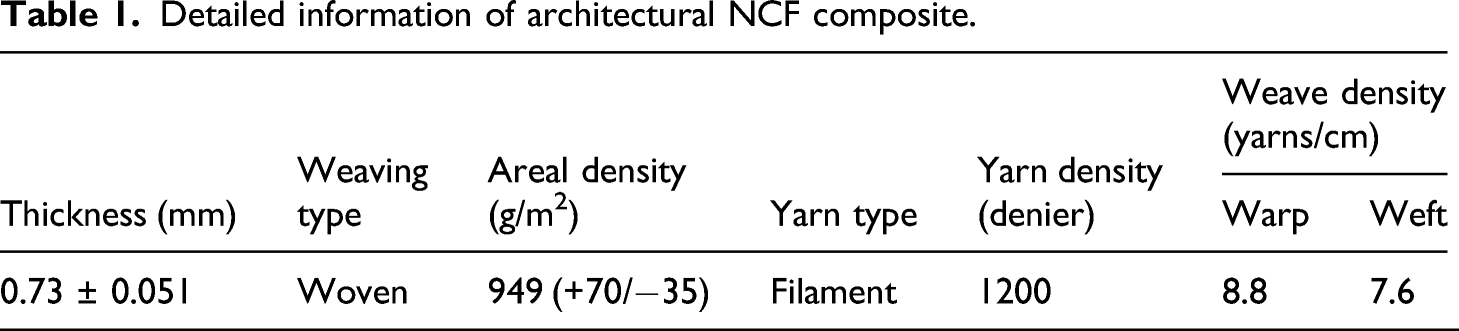
The architectural fabric material Shelter-Rite#PVDF8028, a typical warp-knitted NCF composite, is mainly composed of the structural layer, coatings, and functional layers, as shown in Figure 1(a). This material generally consists of components that permit tailoring of the various material properties to optimize the resulting balance between tensile strength, service life, weight, gas retention, and flexibility. The microscopic structure of warp cross-section is obtained by a scanning electron microscope (SEM), as shown in Figure 1(b). The structural layer of studied material is woven with two non-crimp unidirectional polyester yarns by the coiled yarns. The fabric is woven with 1200 denier polyester fiber bundle. To satisfy the strength requirements, nine and eight yarn counts per centimeter are laid in the warp and weft directions, respectively. The NCF composite is widely used in large-sized and medium-sized air-supported membrane structures. The detailed parameters of PVDF coated NCF composite are summarized in Table 1. Schematic diagrams of microscopic structure (a) and scanning microscope picture (b) for NCF composite. Detailed information of architectural NCF composite.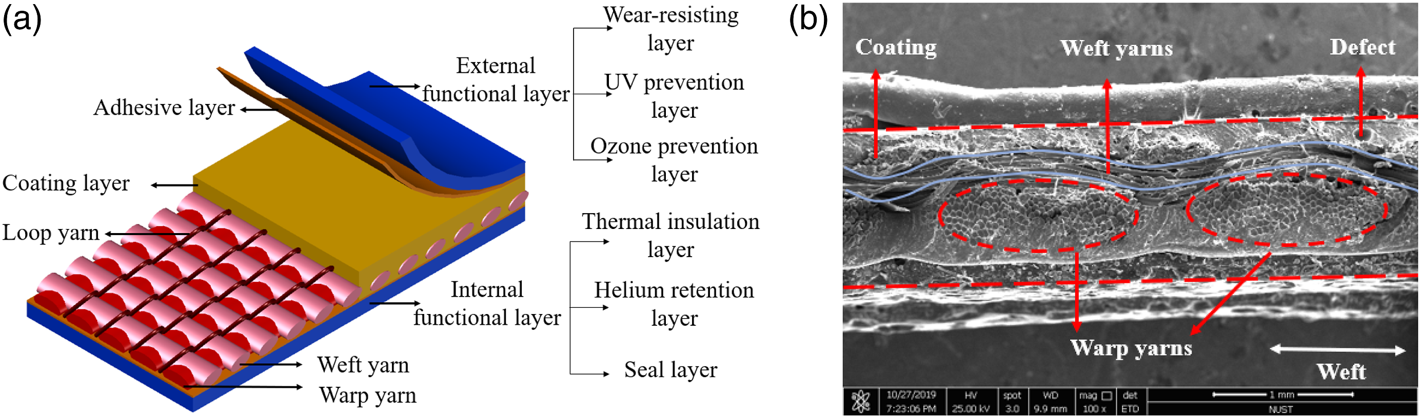
Experimental program
Central crack tearing tests
The tearing specimen of NCF composites with an initial central crack is illustrated in Figure 2. The initial crack was introduced along yarn directions using a utility knife. The sizes of specimens are selected in accordance with the Airship Design Criteria (FAA-P-8110-2)
23
on account of without relevant tearing test standard for architectural coated fabric with central crack. The shadow areas shown in Figure 2 represent clamping regions within the upper and lower jaws. The length and width of effective region between two gauging lines are 101.6 mm and 76.2 mm, respectively. The UTM-4000 testing machine and specimen dimensions of central tearing tests with an initial crack.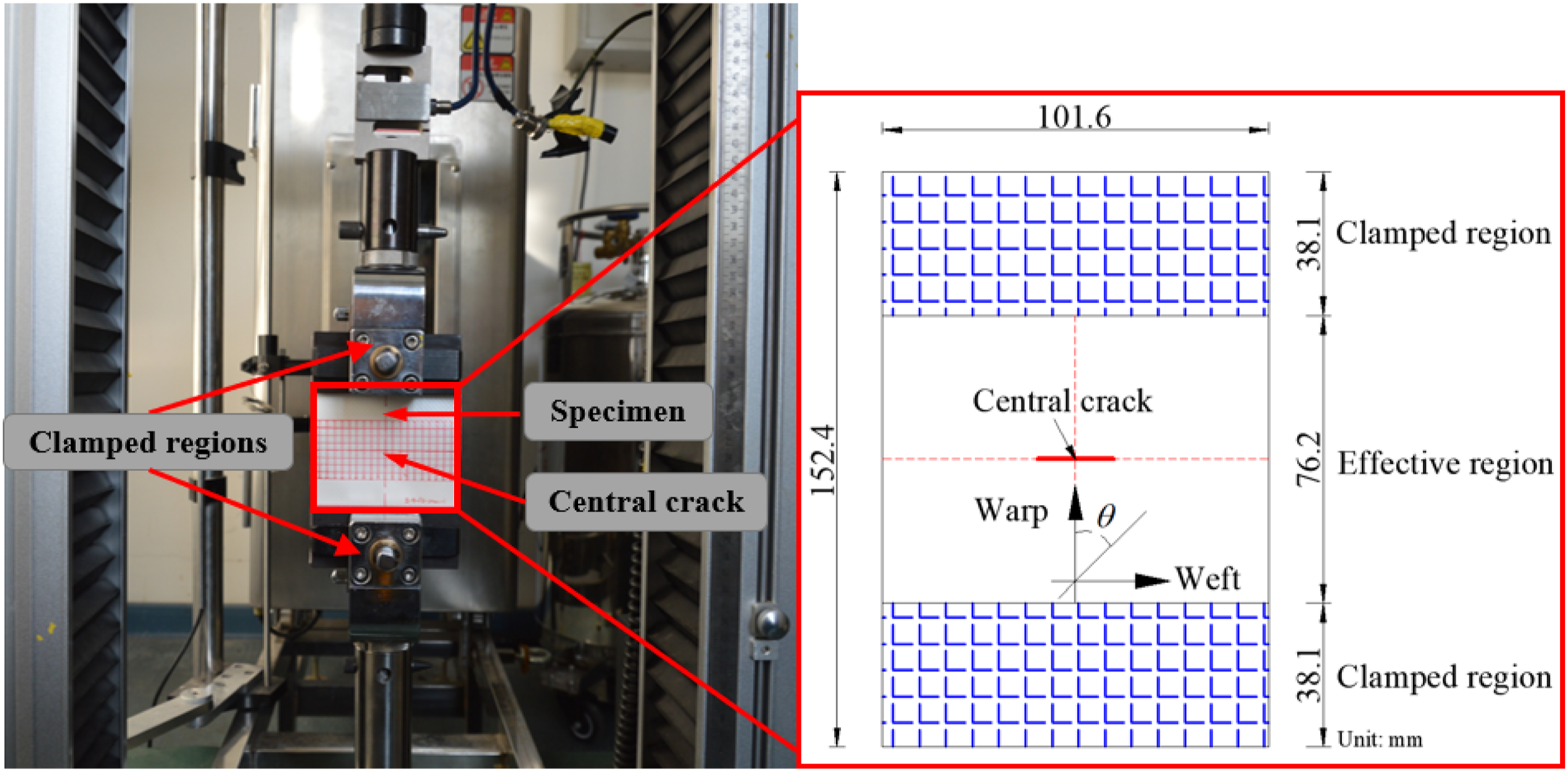
The central crack tearing tests were conducted on a UTM-4000 testing machine (please see Figure 2). The large deformation extensometer and high-precision tensile sensor were used to collect the experimental data, such as displacement and load. For the sake of reducing dynamic effects, the tensile speed was set at 10 mm/min. At least three qualified specimens were conducted to guarantee the reliability of the results. All of the tests were completed at a relative humidity of 65 ± 4.0% and a room temperature of 20 ± 2.0°C according to the ISO 139-2005 standard.
Uniaxial tensile test of yarns
In order to obtain the constitutive parameters of yarns, the uniaxial tensile test of the single yarn was carried out by means of the testing machine UTM-4000, as illustrated in Figure 3. The zigzag winding clamps were selected in this study to avoid the occurrence of slippage and stress concentration, due to the small surface area of yarns. The tensile procedures were conducted at the same loading speed as the central tearing tests. The effective lengths of the separated single warp and weft yarns were both 200 mm. At least three qualified specimens were tested in each direction. Uniaxial tensile machine UTM-4000 and specimen dimensions (mm).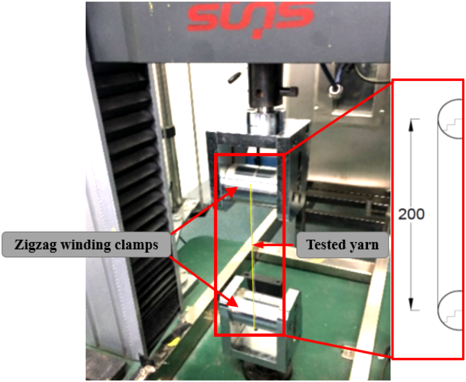
Development of FE models
The dynamic explicit algorithm in a commercial FE software package ABAQUS (version 6.14) is utilized to simulate the central tearing behaviors and damage mechanisms of the coated NCF composites with an initial crack.
Geometric modeling
The NCF composite is composed of the structural layer and various functional layers, in which the yarns and matrix usually exhibit complex interactions. To simplify the FE model, the following hypotheses are applied. • The yarns of NCF composites are considered to homogeneous solids with ellipse cross-sections in accordance with their shapes, and the imperceptible crimp of weft yarns and the inside gap between the fiber bundles of yarns are ignored. • The surface of yarns is supposed to be uniform and smooth, and the influences of surface roughness are considered by introducing the friction effect between yarn and matrix. • Since each functional layer of NCF composite provides little resistance to crack propagation, all functional layers could be considered as a uniform matrix in establishing the FE model, and their initial random flaws are ignored. • The effects of residual stress, residual strain, and environmental factors on mechanical behaviors for NCF composites are not considered in order to improve the efficiency of calculation.
Mirroring precisely the geometric features of the specimen in ABAQUS software, the warp and weft yarns are modeled by an elliptical cross-section extruding along yarns’ centerline. The cross-section view of warp and weft yarns and geometric definitions are shown in Figure 4. The dimensions of the effective area for NCF composites in the FE geometrical model are 101.6 mm in length, 76.2 mm in width, and 0.73 mm in thickness. In order to simply the numerical model, a 1-mm-wide initial crack in the center area of the FE model is established. Schematic diagrams of warp (a) and weft (b) yarn dimensions for studied material in FE model.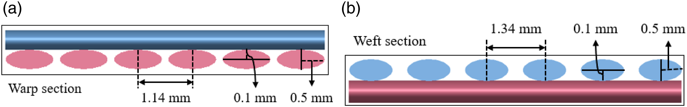
Material properties
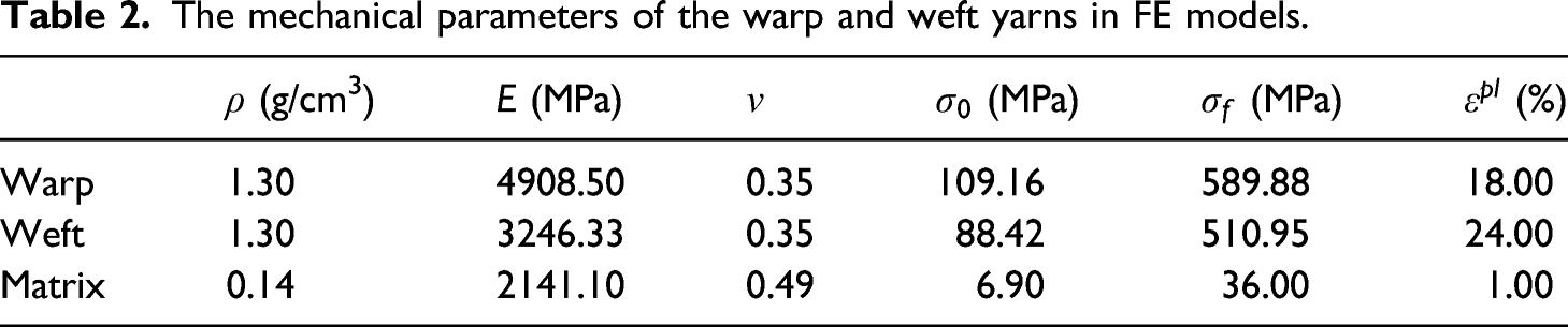
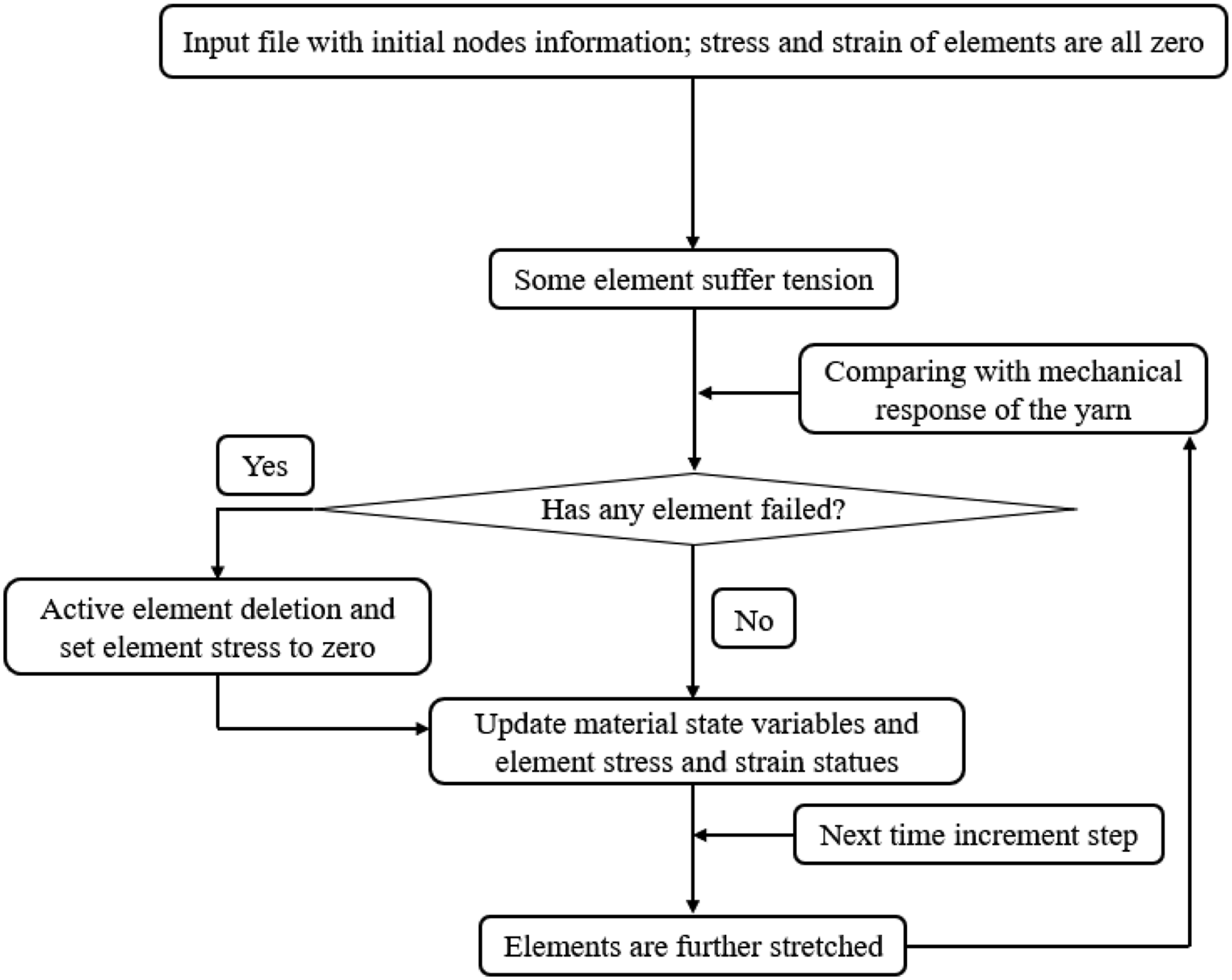
The warp and weft yarns of NCF composites are transversely isotropic materials. However, it is difficult to measure the mechanical parameters through the uniaxial tensile test, and the accuracy also cannot be controlled. Therefore, the warp and weft yarns are regarded as nonlinear isotropic strengthening materials. Yarns experience elastic deformation at the initial loading stage (stage I in Figure 5), and the tensile stress-strain curves of yarns show obvious linear features. As the load increases, the yarns produce gradually plastic deformation, and the tensile stress-strain curves of yarns display obvious nonlinear characteristics (stage II and III in Figure 5). The matrix is mainly composed of polyvinylidene fluoride (PVDF) resin. The mechanical parameters of warp and weft yarns and matrix are listed in Table 2. In Table 2, Stress-strain curves of warp and weft yarns for NCF composites used to the FE models. The mechanical parameters of the warp and weft yarns in FE models. The flow chart of deformation and deletion of elements in the ABAQUS/Explicit FEA solver.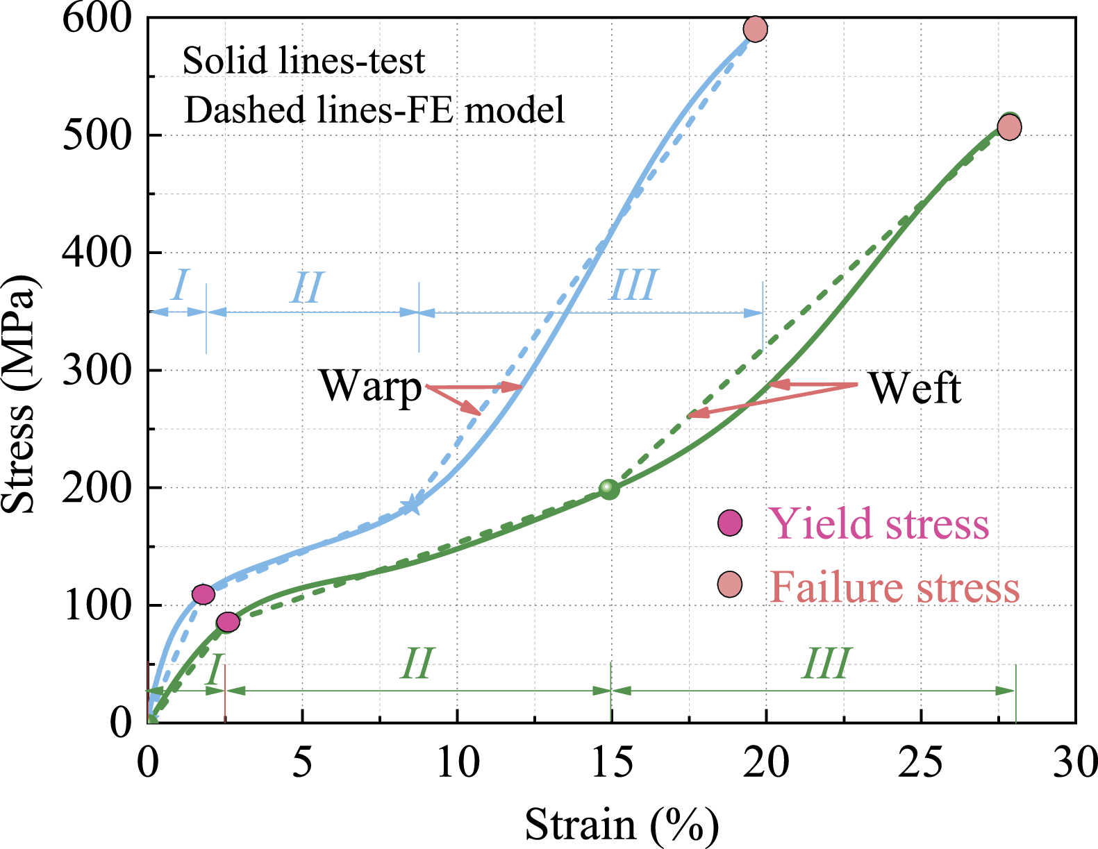
In addition, the post-failure behavior of the NCF composites is governed by the damage evolution parameters, which are associated with material fracture toughness, triaxial stress, and triaxial strain. In the damage evolution law, the failure of the matrix and yarn is determined by the failure displacement. Namely, the failure displacement of material refers to the plastic strain multiplied by the characteristic length of the element. In detail, the failure displacements of the warp and weft yarns are set to be 0.06, and the failure displacement of the matrix is set to be 0.1.
Contact definition
General contact with a frictional coefficient value of 0.2 is used to represent the interaction between the yarns. Tie constraint between the warp and weft yarns is created to simulate the binding effect of coiled yarns. In this study, the domain decomposition method (DDM) is utilized to achieve the contact between matrix and yarns, and the modeling approach of the DDM is plotted in Figure 7(a). This method can efficiently avoid complicated boundary conditions and mesh singularity problems. For the purpose of defining constraints between matrix and yarns, the DDM is implemented by the Embedded function (see Figure 7(b)), which selects the yarn as master surface and the matrix as slave surface. Structural diagrams of the DDM (a) and the Embedded constraint (b) in FE model.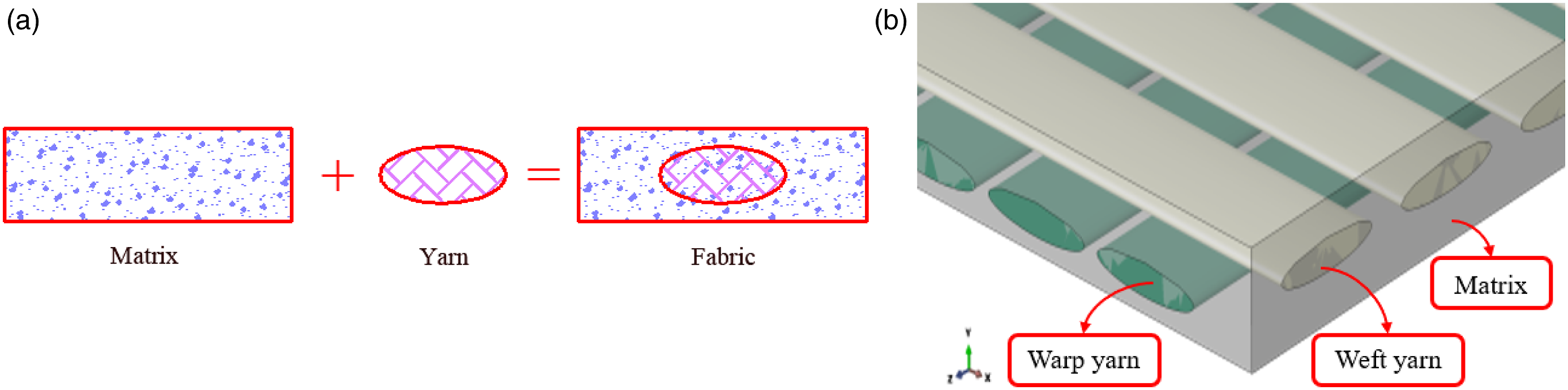
Boundary conditions
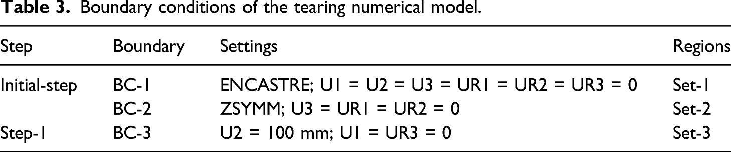
Figure 8 gives a front view, i.e. x-y plane, of the boundary conditions in the FE model. Firstly, three sets are established in the FE model, namely set-1, set-2, and set-3. The set-1, set-2, and set-3 represent sets of yarns and matrix cross-sections for the lower boundary, left and right boundaries, and upper boundary, respectively. Then, three boundary conditions corresponding to these sets are established, namely BC-1, BC-2, and BC-3. The BC-1 corresponding to the set-1 is completely fixed to ensure that upper boundary is perpendicular to the model surface during the loading process. The BC-2 corresponding to the set-2 is free lying along the X-axis. The BC-3 corresponding to the set-3 is applied a specific displacement value of 100 mm, and the displacement increases linearly with time. The load caused by the tensile displacement is uniformly distributed on all nodes of the yarns’ section. Furthermore, the up-arrow represents tensile direction in the FE model. The detailed settings and regions of three boundary conditions are listed in Table 3. Boundary conditions of the FE model with an initial central crack. Boundary conditions of the tearing numerical model.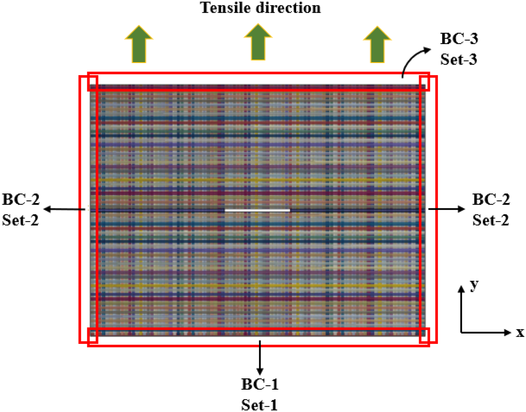
Mesh generation
As illustrated in Figure 9, the FE model of yarns and matrix are meshed with the eight-node hexahedron solid elements with reduced integration (C3D8R), which can effectively avoid the problem of excessive distortion of mesh. The disadvantage of the reduced integration element is that the elements without strain at the integration points are allowed to produce deformation. This phenomenon would elicit a phenomenon called “hourglass” leading to inaccurate calculations. For the sake of preventing excessive deformation, an additional artificial stiffness is added to the element. The total numbers of elements and nodes are 36,740 and 69,684, respectively. Mesh generation of the FE model with an initial central crack.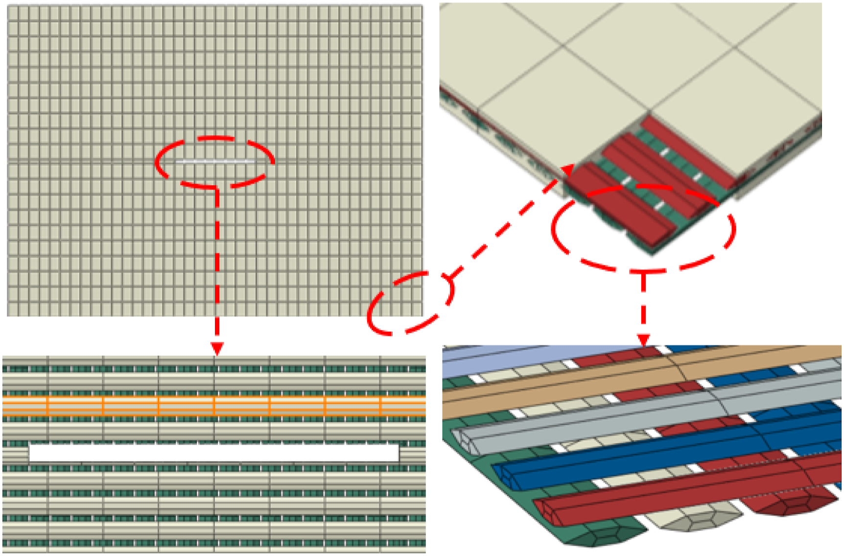
Results and discussion
Validation of FE model
To validate the feasibility and accuracy of the developed FE model, the models with a 20-mm-long initial crack for four bias angles Comparisons of tearing failure morphologies between numerical and experimental results for typical bias angles of 0° (a), 15° (b), 30° (c), and 45° (d). (Unit of stress: Pa).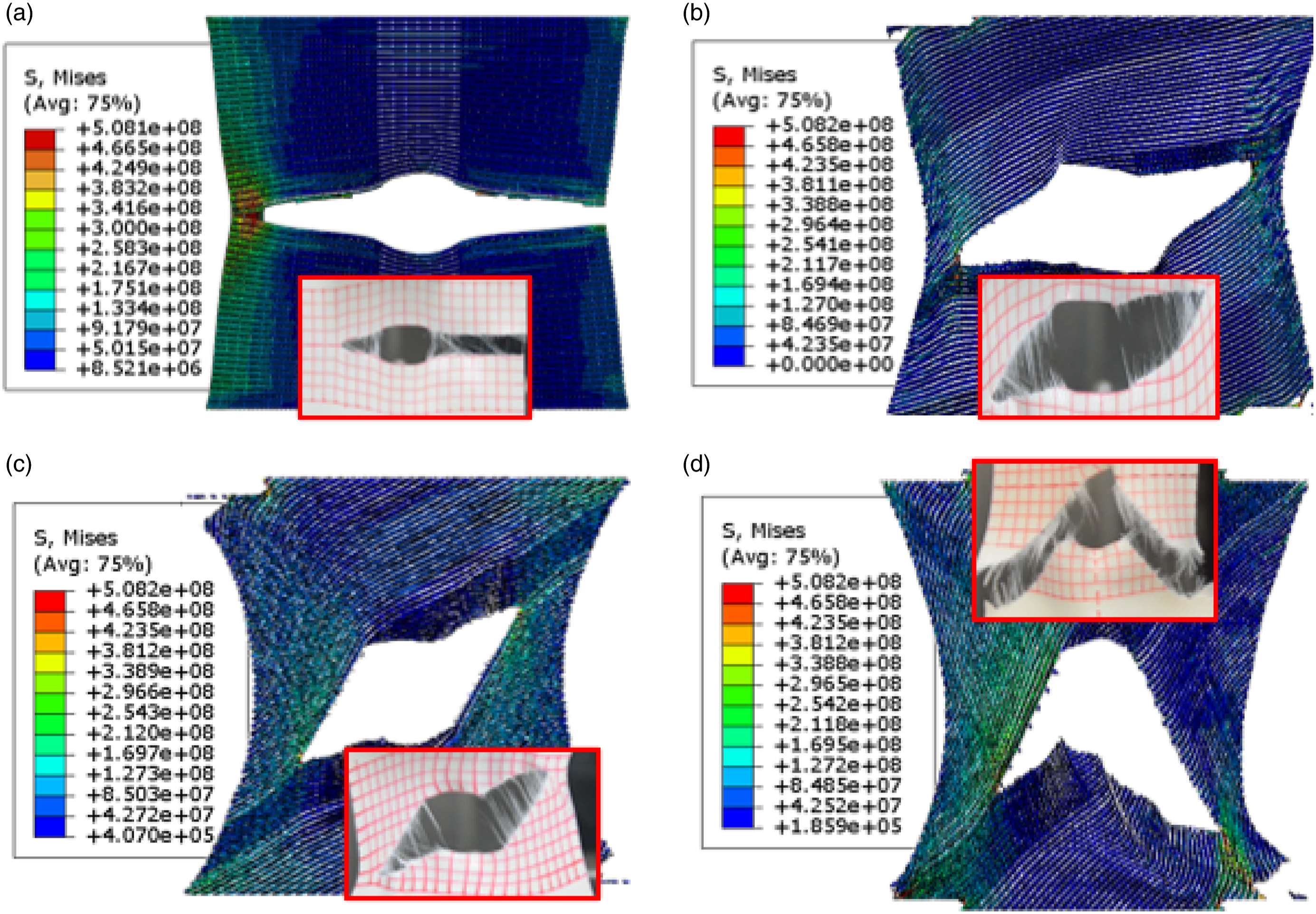
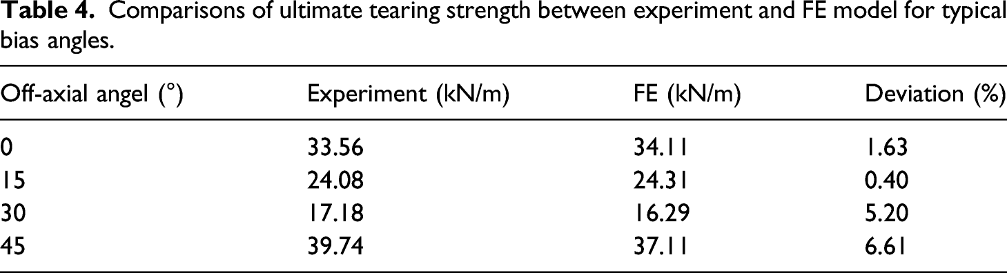
The tearing stress-displacement curves of the NCF composites with typical bias angles obtained from the numerical and corresponding experimental results are plotted in Figure 11, in which the solid and dashed lines represent experimental and numerical results, respectively. For the purpose of presenting a clear illustration, the coordinate origins for bias angles of 15° and 30° are separated and shifted along the displacement axis with a specific interval. In detail, the numerical results, including the curve fluctuations, peak stress, displacement corresponding to the peak stress, and curves’ nonlinearities, show an excellent agreement with the experimental results. It should be noted that some insignificant differences still exist in these curves. For example, due to the slippage of the specimen on the two clamping ends during the test with the bias angle of 45°, the displacement corresponding to the peak stress of the tearing test is slightly higher than that of the FE model. Comparisons of tearing stress-displacement curves between experiments and FE models for typical bias angles.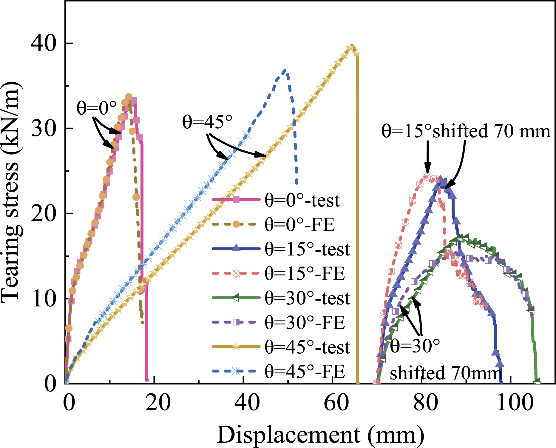
Comparisons of ultimate tearing strength between experiment and FE model for typical bias angles.
Tearing damage mechanisms and failure performances
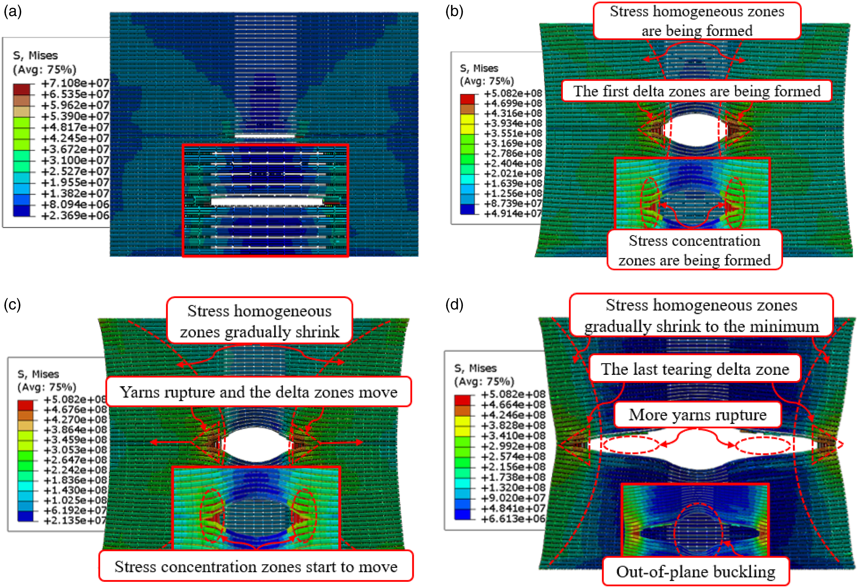
The typical tearing damage morphologies of the NCF composites with a 20-mm-long initial crack and 0° bias angle are shown in Figure 12. As can be observed that the evolution of crack propagation can be divided into four characteristic stages, i.e. initial loading stage, crack opening stage, stable crack propagation stage, and unstable crack propagation stage. The detailed characteristics of each stage are described as follows. (i) Initial loading stage. When the load is exerted to the upper boundary of yarn cross-section at the beginning of loading, the crack is in the unopened state. (ii) Crack opening stage. The initial crack opens progressively and changes into an oval-shaped opening with the increase of load. The load-carrying yarns and matrix show slight debonding phenomenon, and inelastic deformation of load-carrying yarns and slippage of non-load-carrying yarns also produce in the vicinity of crack tips. These deformation and slippage lead to the development of the first tearing delta zones (stress concentration regions). Simultaneously, the stress concentration zones and the stress homogeneous zones, i.e. the main load-carrying zones except the stress concentration zones on both sides of the crack tips, are being formed. As the evolutions of the tearing delta zones, only the load-carrying yarns of the NCF composites are pulled out by the concentrated tensile stress. (iii) Stable crack propagation stage. When the stress value of the first load-carrying yarn at the crack tip reaches its ruptured strength, the yarn breaks, and then with the assists of the non-load-carrying yarns and matrix in the vicinity of crack tip, the load carried by the original yarn is transferred to adjacent undamaged load-carrying yarn. As the load builds up further, the tearing delta zones at the crack tips develop progressively, and the load-carrying yarns rupture one by one, and then the stress concentration zones and stress homogeneous zones gradually move towards the left and right boundaries. The breakage of some load-carrying yarns causes the generation of the new tearing delta zone along the direction of crack propagation. (iv) Unstable crack propagation stage. As the crack propagates alternately on each side, a growing number of load-carrying yarns in the stress homogeneous zones rupture. Additionally, the slippage of yarns at the crack tips leads to occurrence of the new tearing delta zones. When the crack propagates to a critical state, two or three load-carrying yarns (or, even more) rupture simultaneously. Therefore, the area of the stress homogeneous zones decreases sharply, and the loads carried by the remaining yarns increase rapidly resulting in rapid crack propagation until the failure extends to the entire length of the model. For tearing failure of the FE model, the tearing delta zone is the symptom of the approaching tearing for coated NCF composites. Typical tearing propagation processes of NCF composites with a 20 mm-long initial crack and 0° bias angle, including initial loading stage (a), crack opening stage (b), stable crack propagation stage (c), and unstable crack propagation stage (d). (Unit of stress: Pa).
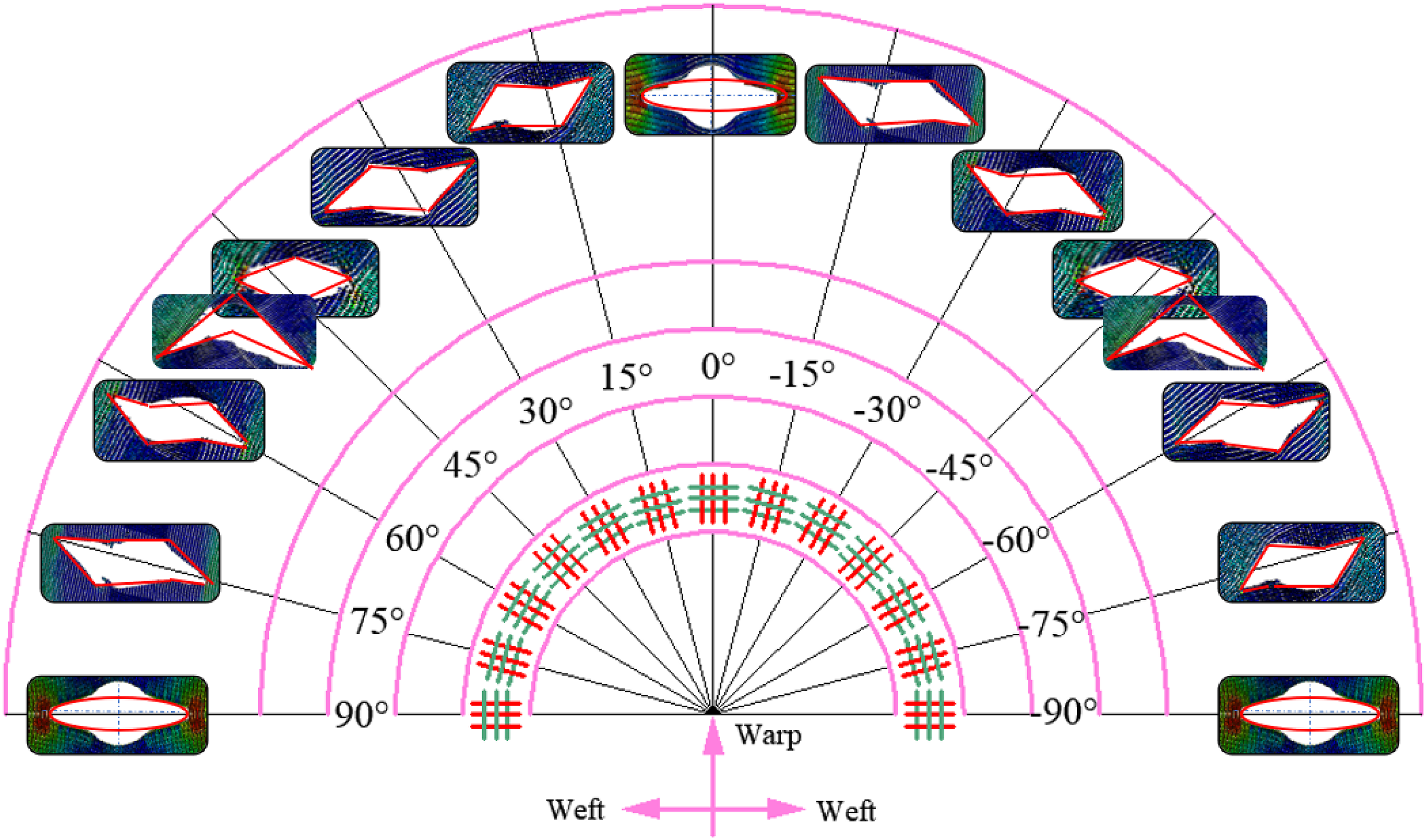
The most significant differences between the on-axial (bias angles of 0° and 90°) and off-axial (bias angles of 15°, 30°, 45°, 60°, and 75°) tearing are the crack-opening shape and the direction of crack propagation due to the rotation of yarns. As illustrated in Figures 13 and 14, there are three types of appearance, i.e. line-shaped, parallelogram-shaped, and diamond-shaped openings, for the NCF composites in terms of the direction of crack propagation. Specifically, for the on-axial models (including initial crack lengths of 20 mm, 40 mm, 60 mm, and 80 mm), their initial cracks could form line-shaped openings, and the propagation of cracks is always perpendicular to the loading direction. For the off-axial model (initial crack length of 20 mm), their initial cracks could form parallelogram-shaped openings. For 15° and 30° bias angles, cracks propagate along the weft direction. For 15° and 30° bias angles, cracks propagate along the warp direction. However, for the model with the 45° bias angle, the crack firstly takes a diamond shape opening and then propagates rapidly like an inverted “V” shape without obvious symptom, and the crack propagates simultaneously along warp and weft direction. Therefore, the yarn orientation for the off-axial model could significantly influence the crack propagation direction, which could be attributed to the rotation of the yarn. Typical tearing damage morphologies of the studied materials for initial crack lengths of 40 mm (a), 60 mm (b), and 80 mm (c). (Unit of stress: Pa). Schematic drawing of typical damage modes obtained from FE models with an initial central crack for different bias angles.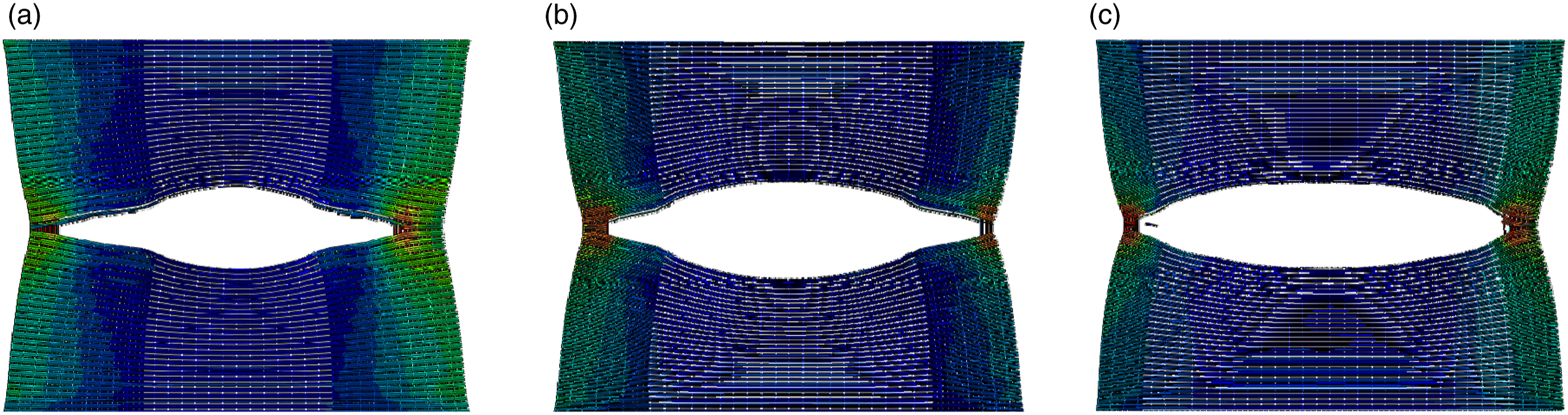
Furthermore, due to the lack of out-of-plane constraints at the ends of the cut yarns, the NCF composites near the cracks produce unneglectable “out-of-plane buckling” phenomenon 39 (please see Figure 12(d)). The out-of-plane buckling could lead to the reduction of material strength since the yarns in the vicinity of crack tips resist both tensile stress and additional bending moment.
Effect of initial crack length
To investigate the impact of the initial crack length (2l
c
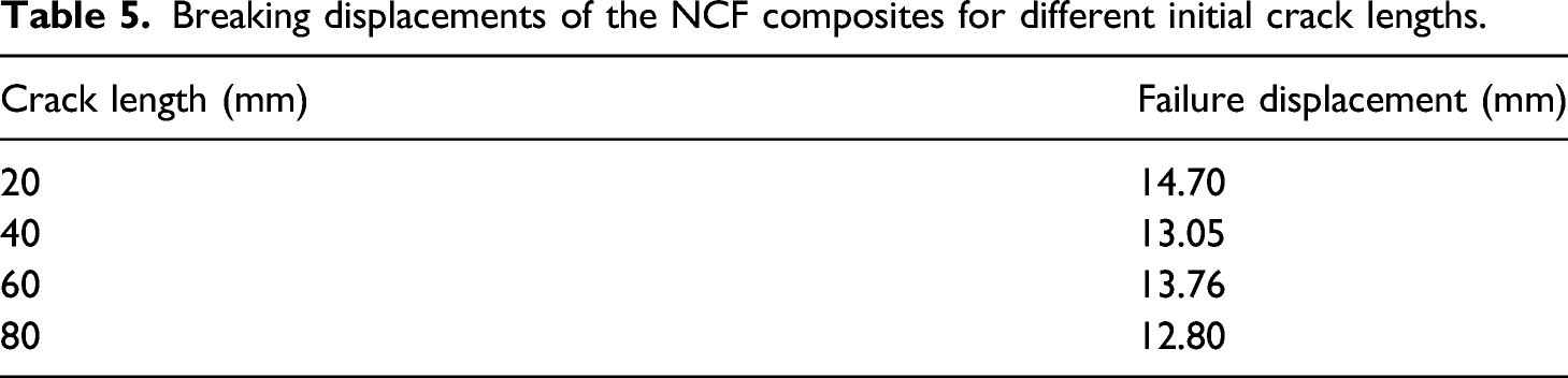
) on tearing behaviors, the tearing stress-displacement curves of NCF composites with a 0° bias angle for different initial crack lengths are plotted in Figure 15. Obviously, the length of initial crack has a noticeable influence on the mechanical properties of NCF composites. The ultimate tearing strength, i.e. peak stress, depends strongly on the initial crack length. When the number of cut-off longitude yarns (yarns parallel to the loading direction) increases, the loads carried by the remaining longitude yarns increase, whereas the ultimate tearing strength depends on the total loads when the first load-carrying yarn ruptures. Therefore, the ultimate tearing strength decreases significantly with the increase of initial crack length. The failure displacements, i.e. the displacement corresponding to the peak stress, of NCF composites for the lengths of different initial cracks are listed in Table 5. It can be found that the failure displacements are close to each other. The main reason is that the woven structure and the transverse yarn (yarns perpendicular to the loading direction) limit the deformation of material. Specifically, the failure displacements for the initial crack lengths of 20 mm and 80 mm reach the maximum (14.70 mm) and the minimum (12.80 mm), respectively. More precisely, the failure displacement for the initial crack length of 20 mm is only 12.90% smaller than that of the initial crack length of 80 mm. The length of the initial crack also has effect on the tearing stiffness, i.e. the slope of the curve prior to the peak stress, of NCF composites. Tearing stress-displacement curves of different initial crack lengths. Breaking displacements of the NCF composites for different initial crack lengths.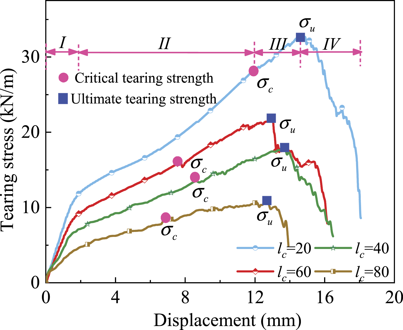
In Figure 15, the obvious quasi-yield behaviors can be observed. However, there is no consistent approach to determine yield stress characterizing visibly nonlinear features of NCF composites. To obtain the accurate mechanical properties, such as the materials’ yield stress and stiffness, a method with plausible mathematical meaning is proposed. As illustrated in Figure 16, the nonlinear piecewise fitting is first conducted on the FE result, and two corresponding fitting lines k
1
and k
2
intersecting at point B are obtained. Subsequently, a horizontal line a crossing point B is plotted, and the intersection (point A) is gained for line a and FE result, which could be considered as the quasi-yield point of NCF composites with an initial central crack. Finally, point A is linked to the beginning point (point O) and ending point (point C) of the curve, respectively, and connecting lines b and c are gained. In this paper, the slopes of lines b and c are utilized to characterize the first and second tearing stiffness (the first tearing stiffness and second tearing stiffness) of the NCF composites for different initial crack lengths, respectively. Computation drawing for the identification method of mechanical properties of NCF composites.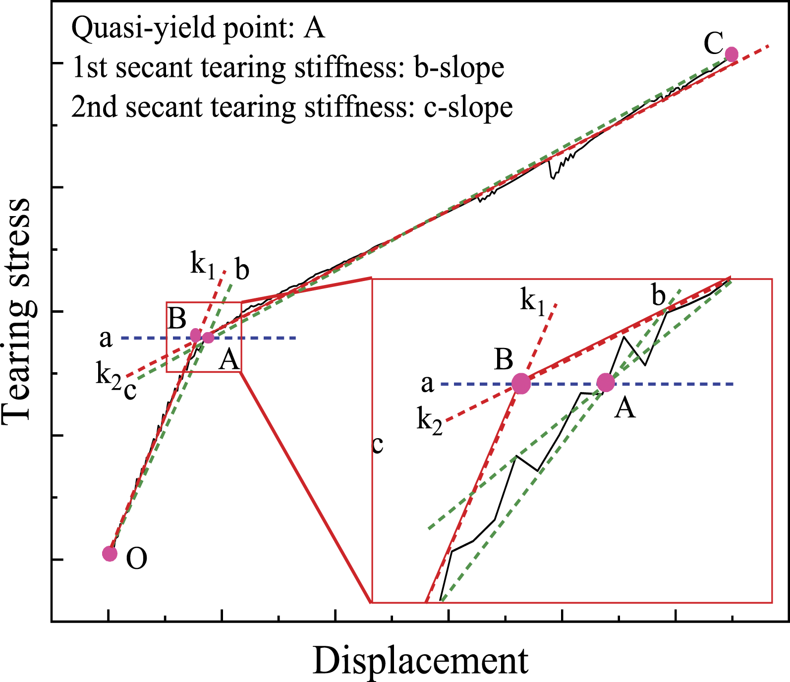
Using the proposed identification method, the variations of quasi-yield stress and the first and second tearing stiffness for different initial crack lengths are obtained and plotted in Figure 17. It is evident that the length of the initial crack has a marked influence on the yield stress and first tearing stiffness of NCF composites, but has a slight influence on the second tearing stiffness. In detail, when the initial crack length changes from 20 mm to 80 mm, the yield stress decreases nonlinearly, approximately by 51.50%. However, the varying trends of the first and second tearing stiffness are different from the yield stress, and they are both linear as shown in Figure 17. Furthermore, the average values for the first and second tearing stiffness are 4.72 MPa and 1.09 MPa, respectively. The average value of the first tearing stiffness of NCF composites is 76.92% lower than that of the second tearing stiffness. The variations of quasi-yield stress and tearing stiffness of NCF composites for different initial crack lengths.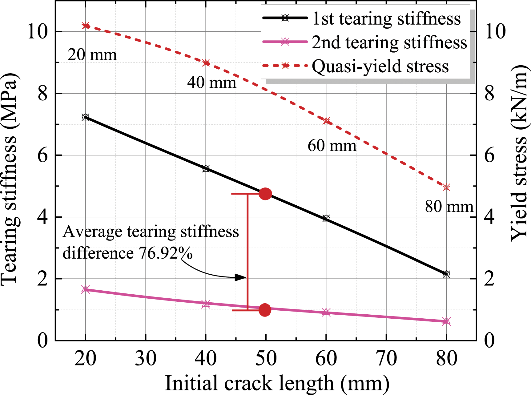
For the NCF composite used for air-supported membrane structure, it is critical to figure out the limiting value of stress in which the crack begins to propagate since the crack propagation more or less accelerates the overall failure of the material. The force can be described as the critical tearing stress that leads to crack propagation. Since the thickness of the fabric is much smaller than the length, a linear load is used to analyze the materials’ mechanical properties. Specifically, for a 2l
c
(mm) length crack under the tensile load F (N), the tearing stress 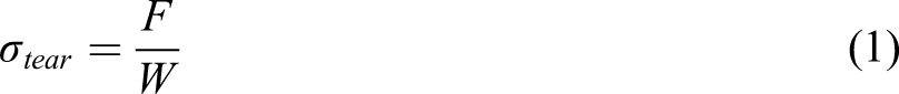
The critical tearing strength, i.e. critical stress value, and ultimate tearing strength of NCF composites for various initial crack lengths are listed in Figure 18. In order to obtain the relationships between the tearing strengths and initial crack lengths, the least square method is used by fitting the tearing strength values. Two proper cubic functions (R2>0.99) can be utilized to express the relationships between the tearing strengths and initial crack lengths, as written in equations (2) and (3) as follows: The variations of critical tearing strength and ultimate tearing strength for different initial crack lengths.

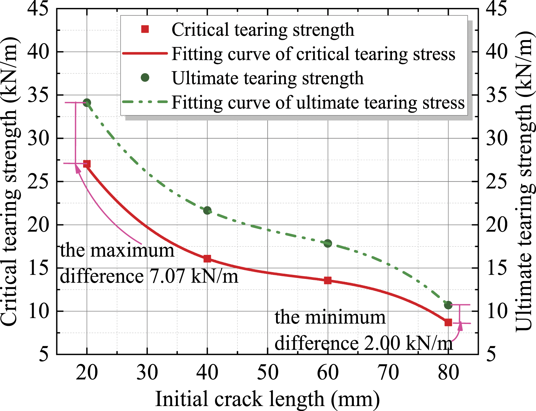
As shown in Figure 18, the critical tearing strength and ultimate tearing strength decrease nonlinearly with the increase of initial crack length. When the initial crack length changes from 20 mm to 80 mm, the critical tearing strength and ultimate tearing strength values decrease by 18.02 kN/m and 23.41 kN/m, approximately 67.40% and 38.60% of the value for the 20-mm-long initial crack, respectively. Furthermore, the critical tearing strength and ultimate tearing strength values are gradually close to each other as the initial crack length increases. Specifically, the maximum difference (7.07 kN/m) and the minimum difference (2.00 kN/m) appear in the initial crack lengths of 20 mm and 80 mm, respectively. Therefore, for the 80-mm-long initial crack, when the first yarn reaches ruptured strength, the failure rapidly extends over the length model due to the increase of the cut-off load-carrying yarns.
Effect of yarn orientation
To investigate the effect of the yarn orientation Typical characteristic stages of tearing stress-displacement curves of NCF composites for seven bias angles.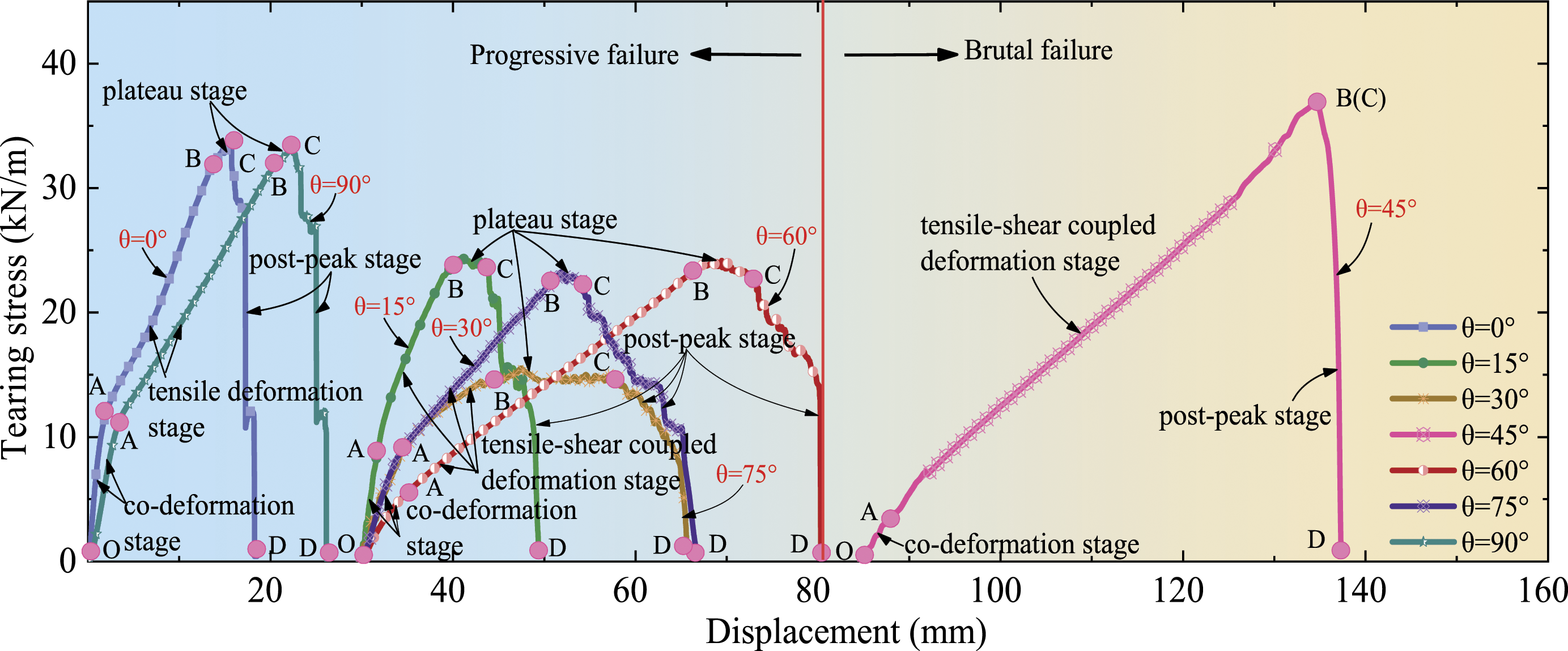
OA (the co-deformation stage). The coated NCF composite behaves as a virgin elastic material with no damage, and the yarns and matrix are stretched together to resist tearing propagation. The tearing stress-displacement curves show a relatively small increase in the displacement in the case of a significant increase in tearing stress. In this stage, the tensile stress or tensile-shear coupled stress is mainly governed by the matrix, and thus the typical tearing stress-displacement curves for on-axial and off-axial models are similar with respect to the tendencies and slopes of curves.
AB (the tensile deformation stage or tensile-shear coupled deformation stage). A quasi-linear stage. The matrix gradually loses its load-carrying capacity, and the mechanical behaviors of material are mainly governed by yarns. Hence, the load-carrying capacity of NCF composite increases sharply with the increase of the displacement. For the on-axial models, the mechanical behaviors of material are mainly dominated by the warp or weft yarns. For the off-axial models, the shear deformation should be considered due to the rotation of the yarns, and the existence of shear deformation leads to the off-axial model in the tensile-shear coupled deformation state. In this stage, when the bias angle changes towards the 45° direction, the slopes of curves for off-axial models are significantly lower than those of on-axial models due to the low shear stiffness of the NCF composite.
BC (the plateau stage). After reaching the critical tearing stress, the tearing delta zones progressively move outwards owing to breakage of yarns, the number of remaining load-carrying yarns in stress homogeneous zones decreases. As the deformation increases, the stress of remaining load-carrying yarns continues to increase in the vicinity of crack tips. When the load-carrying yarns rupture one by one in the tearing delta zones, high strain energies stored by load-carrying yarns are sharply released, and then the new load-carrying yarns accumulate quickly these high strain energies. As a result, the tearing stress of studied material reaches a quite high level and the tearing curve shows some fluctuation features. There is a peak value during the fluctuation process, i.e. the ultimate tearing strength.
Both on-axial and off-axial curves experience fluctuations in this stage, however, there are also some differences among those curves. The most obvious difference is the number of peaks, which is mainly attributed to the different ruptured phenomena of yarns. For on-axial models, the direction of crack propagation is perpendicular to the loading direction. During the loading, most yarns rupture almost simultaneously, and thus the tearing stress for on-axial models rapidly plunges to the residual stress after reaching the peak, which leads to few peaks and short duration in this stage. For off-axial models, part of yarns is pulled out from the matrix and the remaining yarns rupture when reach their breaking strengths. The yarn pullout process needs to absorb more energy than the ruptured process.24,38 Furthermore, the shearing effect hinders the slippage of the yarns at crossover points, and the resistance of damaged NCF to resist tearing propagation is markedly enhanced. Consequently, compared with on-axial models, there are longer durations and more peaks for the curves of off-axial models in this stage. Especially, for the 45° off-axial model, global failure happens suddenly without obvious crack propagation process, i.e. no plateau stage in tearing stress-displacement curve, and the evolution of tearing damage transforms from the crack opening stage into unstable crack propagation stage, which skips the stable crack propagation stage. This failure mode can be defined as the brutal failure. For other bias angles mentioned above, their failure mode can be described as the progressive failure.
CD (the post-peak stage). After reaching the ultimate tearing stress, an increasing number of load-carrying yarns rupture as the deformation further increases, and even two or three yarns (or, even more) often rupture simultaneously until the failure extends to the entire length of the model. Therefore, the tearing stress rapidly plunges to a very low level. Prior to model failure, this stage also shows slight fluctuation features for off-axial models (except 45° off-axial model). This could be attributed to the fact that yarns are damaged not so much in a ruptured manner as in a pullout manner in the last tearing delta zones of numerical simulation.
The materials’ strength is a vital mechanical property for membrane structural design. In this paper, the displacement corresponding to the critical tearing strength is the breaking displacement, and the displacement corresponding to the ultimate tearing strength is the failure displacement. The tearing strength and corresponding displacement of NCF composite for different bias angles are illustrated in Figure 20. Obviously, the NCF composite shows unneglectable orthotropic characteristics, and the yarn orientation has a significant effect on the mechanical properties of NCF composites. When the bias angle changes towards the 45° direction, the critical tearing strength and ultimate tearing strength of NCF composites first plunge to the bottom and then increase to the maximum value, while the breaking displacement and failure displacement appear to increase monotonically. Specifically, for 0° bias angle, both critical tearing strength and ultimate tearing strength reach their second peaks (33.56 kN/m and 34.11 kN/m), but both breaking displacement and failure displacement reach their minimums (12.39 mm and 14.00 mm). For bias angle of 90°, the critical tearing strength and ultimate tearing strength are slightly lower (4.00% and 2.90%) than corresponding values for bias angle of 0°, respectively, however, breaking displacement and failure displacement do not show the same tendency. The breaking displacement and failure displacement for bias angle of 90° are visibly larger (41.18% and 37.1%) than those of bias angle of 0°. The difference in tearing strength of NCF composite between 0° and 90° bias angle is mainly attributed to the difference of yarns’ woven densities in warp and weft directions. The woven density of NCF composite for warp yarn (8.8 yarns/cm) is larger than that of weft yarn (7.6 yarns/cm). For bias angle of 45°, both critical tearing strength and ultimate tearing strength reach their peaks, and breaking displacement and failure displacement also exhibit the same tendency. Overall, with the increase of bias angle, the variation tendencies and shapes of critical tearing strength and ultimate tearing strength curves are “W” shapes with a peak in 45° bias angle, and the variation tendencies and shapes of breaking displacement and failure displacement are inverted “V” shapes with a peak in 45° bias angle. The variations of the tearing strength and breaking displacement of NCF composites for different bias angles.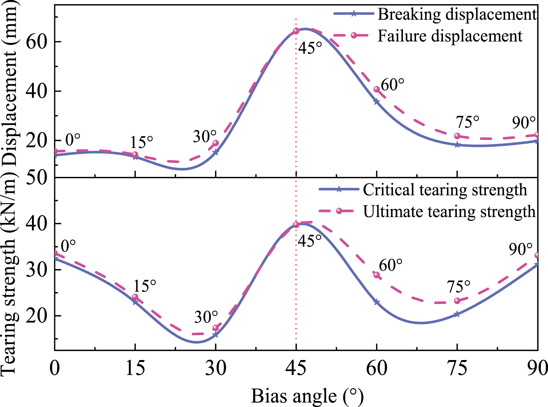
Figure 21 shows the Mises equivalent stress nephograms of NCF models for four typical bias angles, including 0°, 15°, 30°, and 45°, in the critical tearing state to reveal the effect of yarn orientation on tearing strength. Obviously, some differences would be significantly observed in stress concentration and stress distribution scope of load-carrying yarns. For 0° bias angle, load-carrying yarns are clamped at both ends. As the load increases, the stress is mainly concentrated on four or five yarns near crack tips. When the first load-carrying yarn at the crack tip ruptures, the stress is immediately redistributed, and more warp yarns bear the applied load simultaneously to resist crack propagation. Hence, the stress level continues to significantly increase after reaching the critical tearing strength of NCF composite. For 15° and 30° bias angles, load-carrying yarns are clamped at both ends and one end. Clamped warp yarns at both ends are the primary load-carrying yarns. As the load rises, the stress is mainly concentrated on one or two yarns in the vicinity of crack tips. Furthermore, it can be found that the number of load-carrying warp yarns for 30° bias angle is less than that of 15° bias angle due to the reductions of the number of warp yarns clamped at both ends. Therefore, the critical tearing strength and ultimate tearing strength gradually decrease with the increase of bias angle. For 45° bias angle, load-carrying yarns are clamped at both ends and one end. Clamped warp and weft yarns at both ends are primary load-carrying yarns. As the load increases, the stress is mainly concentrated on one or two yarns in the vicinity of crack tips. The stress of load-carrying yarns clamped at one end is redistributed by adjusting their deformation, and thus concentrated stress in the vicinity of crack tips is dispersed to warp and weft yarns. Compared with other bias angles, load-carrying warp and weft yarns exhibit a more uniform stress distribution and a more sufficient deformation, owing to their symmetrical positions. The yarns in two directions can take joint action to offer the resistance against creak propagation. As a result, the model of 45° bias angle exhibits higher critical tearing strength and ultimate tearing strength than mentioned other bias angles. The equivalent stress nephograms of NCF models in critical tearing state for bias angles of 0° (a), 15° (b), 30° (c), and 45° (d). (Unit of stress: Pa).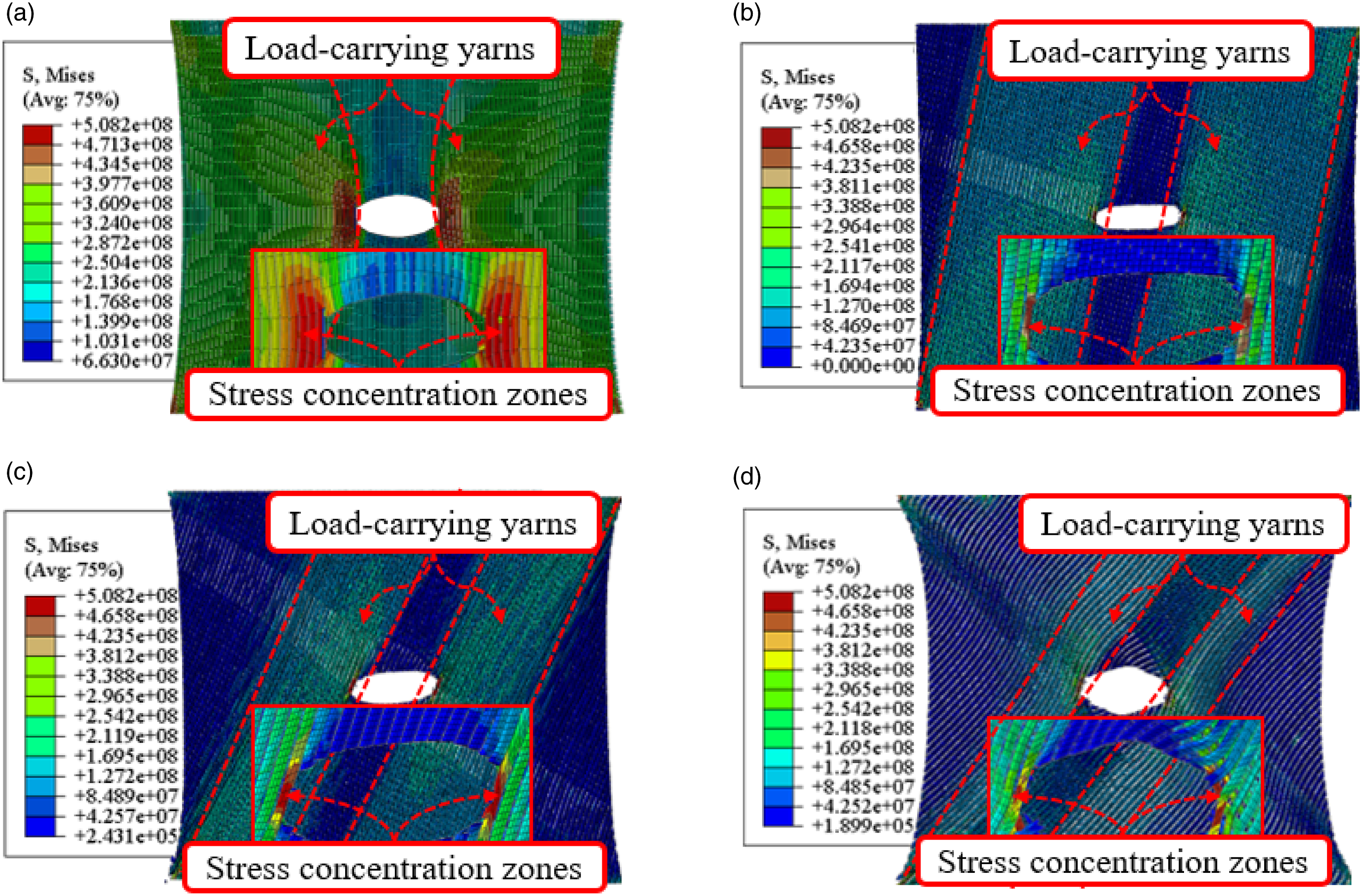
In order to further study the influence of yarn orientation on the tearing strength of NCF composites, the ultimate tearing strength of warp and weft load-carrying yarns for different bias angles are plotted in Figure 22. As the bias angle increases, the contribution of warp yarns to the load-carrying capacity decreases nonlinearly, and the contribution of weft yarns to the load-carrying capacity rises nonlinearly. For 0° bias angle, warp yarns bear all loads and provide the resistance against crack propagation. As the bias angle increases from 15° to 30°, due to the rotation of yarn, the ultimate tearing strength of warp yarns decreases by 11.4 kN/m, yet the ultimate tearing strength of weft yarns only increases by 2.73 kN/m. When the bias angle increases to 45°, the yarns in two directions can take joint action to offer the resistance against creak propagation, and the ultimate tearing strengths for warp and weft yarns reach their local peak values. The ultimate tearing strength for warp yarns is slightly higher than that of weft yarns due to its higher woven density. When the bias angle increases to 75°, the ultimate tearing strength for weft yarns is significantly higher than that of warp yarns. When the bias angle rises to 90°, weft yarns bear all loads and offer the resistance against crack propagation. Obviously, the ultimate tearing strength of NCF composite is strongly correlated to the load-carrying capacity of microscopic material. As for the design practice and structural safety assessment, it is recommended to conduct the fabric structural analysis with a lower limit of tearing strength given the significant variation in tearing strength. The lower limit can be derived from the data of 30° bias angle for the studied NCF composites. The contribution of warp and weft yarns to the load-carrying capacity of the model for different bias angles.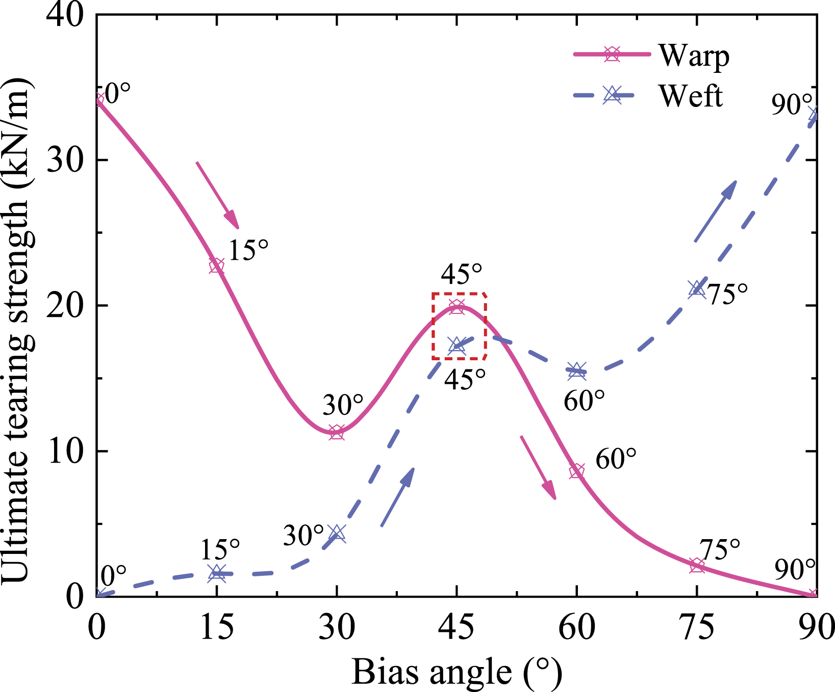
Effect of arch-shaped bend of weft yarn
During the manufacture, warp yarn is subjected to tension but no tension is applied to weft direction. This manufacture could cause slight crimp in weft direction, i.e. the arch-shaped bend. In this paper, the ratio of the maximum bent distance to the length of the weft yarn is defined as the arch curvature of the weft yarn. According to Wang et al.,
40
the weft yarns model with downward arching bend (arch curvature of 3.6%) is established based on the initial FE model. There are two kinds of layouts for the arch-shaped bend of the weft yarn, i.e. global arch-shaped and local arch-shaped bend, for NCF composites, as illustrated in Figure 23. The layouts of global arch-shaped bend (a) and local arch-shaped bend (b) based on the initial FE model.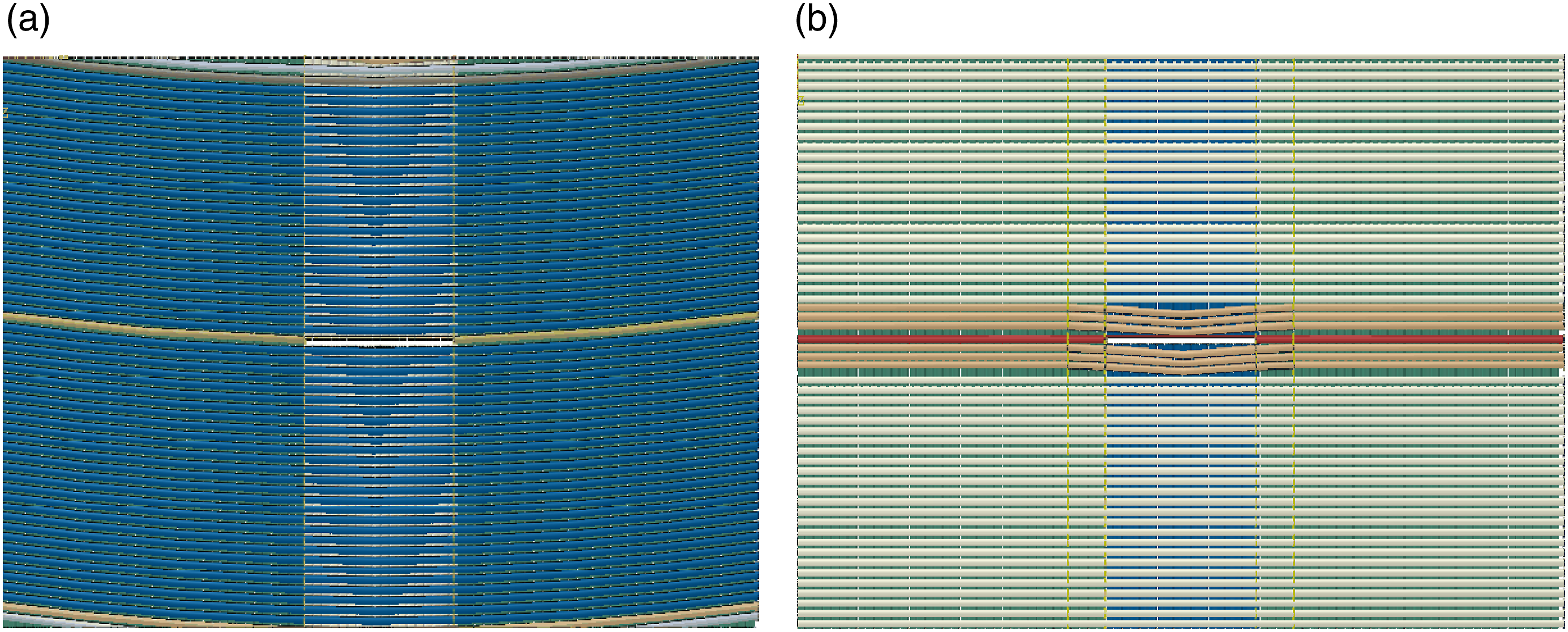
To investigate the effect of the arch-shaped bend of weft yarn on tearing behaviors, the tearing stress-displacement curves of NCF composites with a 20 mm-long initial crack and 0° bias angle for different arch-shaped bend layouts are plotted in Figure 24. It could be observed that the arch-shaped bend of the weft yarn has little influence on the first and second tearing stiffness. However, ultimate tearing strength and failure displacement are affected by the arch-shaped bend of the weft yarn. Specifically, the ultimate tearing strength for the global arch-shaped bend reaches 31.66 kN/m with a failure displacement of 12.77 mm, and the ultimate tearing strength for the local arch-shaped bend reaches 31.94 kN/m with a failure displacement of 14.49 mm. The ultimate tearing strengths for the global arch-shaped bend and local arch-shaped bend are 7.18% and 6.36% lower than that of the no arch-shaped bend, respectively. Obviously, the existence of the arch-shaped bend of weft yarn could decrease the load-carrying capacity of NCF composite. However, ultimate tearing strength for the local arch-shaped bend is only 0.88% lower than that of the global arch-shaped bend. Hence, the arch-shaped bend of weft yarn in the vicinity of crack is more essential factor in effecting the load-carrying capacity of the studied material compared with the global arch-shaped bend. The tearing stress-displacement curves of NCF composites for typical arching bend of weft yarn.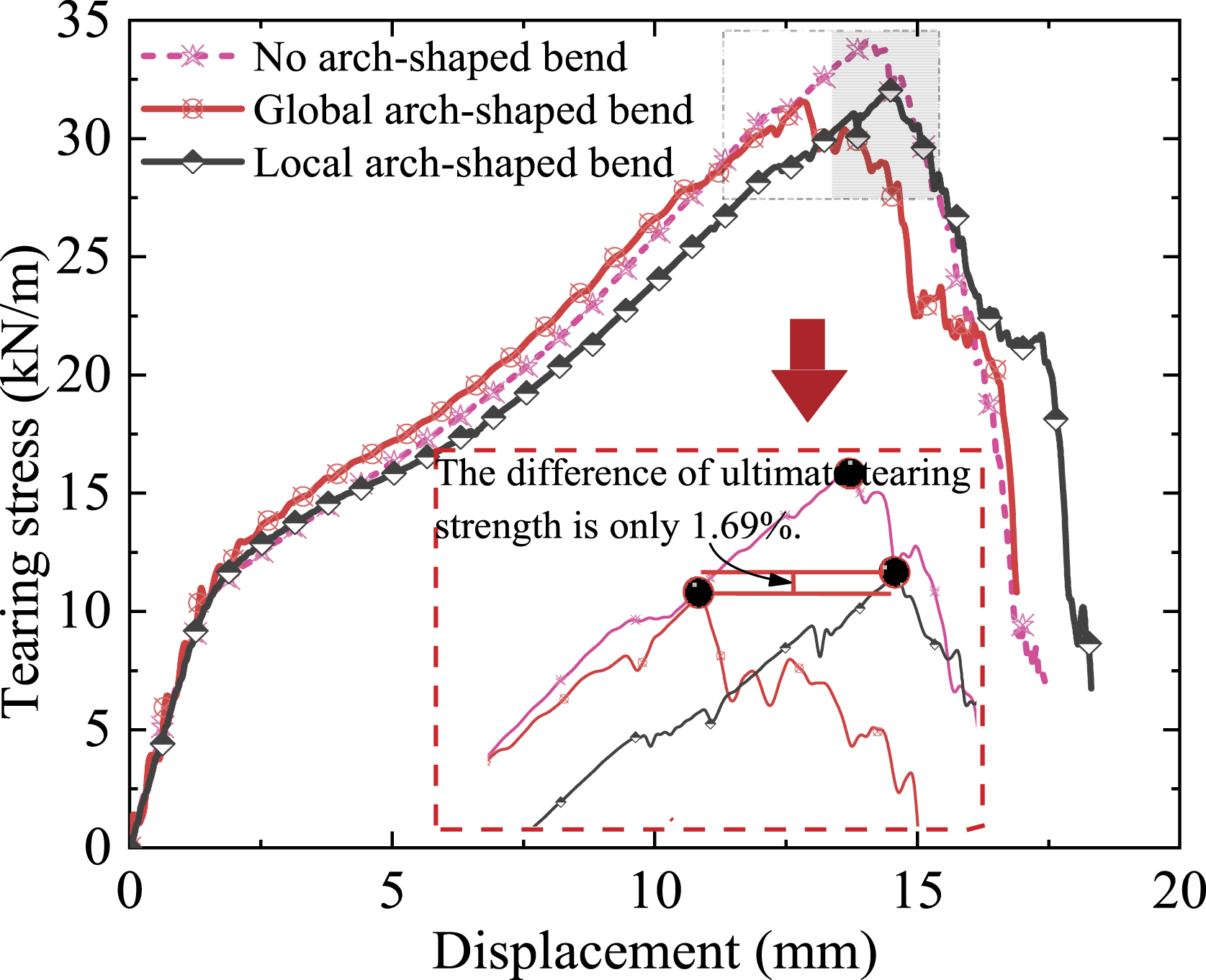
According to reference [40], the arch curvature of the weft yarn is set to be 3.6% but generally does not exceed 9.5%. Therefore, in order to further analyze the influence of the local arch-shaped bend of the weft yarn on ultimate tearing strength, the range of the arch curvatures of the weft yarns from 3.6% to 7.2% with an increment of 18% are selected to conduct typical numerical simulation, and the relationship between ultimate tearing strength and arch curvature for typical initial crack lengths are plotted in Figure 25. For 20 mm-long and 40 mm-long initial cracks, it could be found that the ultimate tearing strength gradually decreases with the increase of arch curvature. When the arch curvature increases to 5.4%, the ultimate tearing strength gradually tends to stabilize. For 60 mm-long and 80 mm-long initial cracks, the arch curvature has a slight effect on the ultimate tearing strength. Relationship between ultimate tearing strength and arch curvature for different initial crack lengths.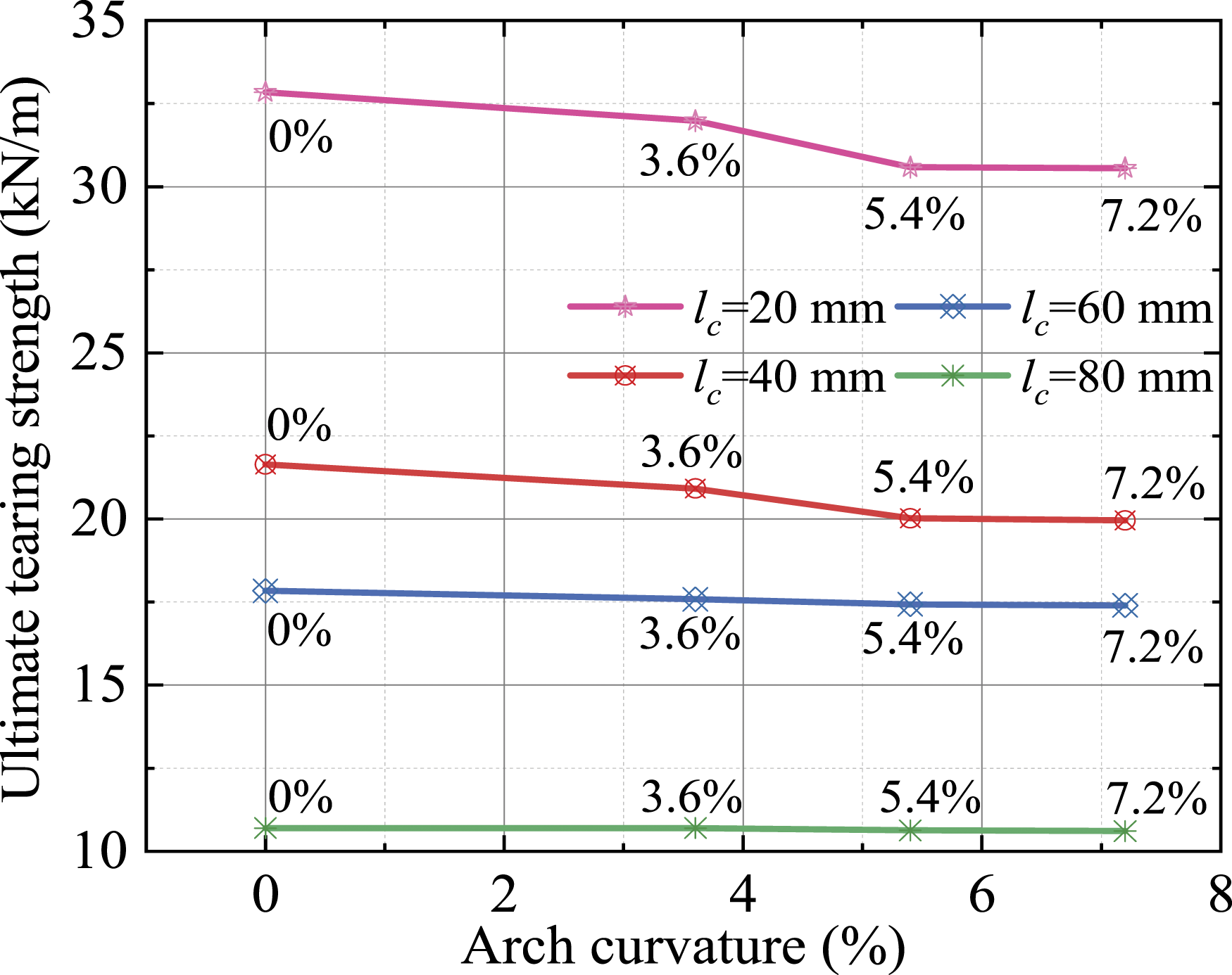
The above results indicate that the arch-shaped bend of weft yarn is essential factor in effecting the load-carrying capacity of NCF composite with an initial central crack. Therefore, the existence of the arch-shaped bend of the weft yarn should be avoided as much as possible in actual application. In order to obtain a comprehensive understanding for the arch-shaped bend of the weft yarn, future work should focus on the influence of the arch-shaped bend of the weft yarn on tearing behaviors for different yarn orientations, which may facilitate more accurate analysis in numerical simulation.
Conclusions
This paper has deeply studied the central tearing behaviors and damage mechanisms of NCF composites by means of the numerical simulation with taking various initial crack lengths, different yarn orientations, and arch-shaped bend of weft yarn into account. A microscopic FE model is established to simulate the tearing propagation process of NCF composites with an initial central crack. Through analyzing these numerical results, some meaningful findings and conclusions could be drawn.
The evolution of crack propagation can be divided into four characteristic stages, i.e. initial loading stage, crack opening stage, stable crack propagation stage, and unstable crack propagation stage. As the crack propagates constantly, for the on-axial models, the propagation of initial cracks is always perpendicular to the loading direction, whereas the yarn orientation for the off-axial model could significantly influence the crack propagation direction due to the rotation of the yarn.
The length of the initial crack has a significant effect on the ultimate tearing strength, failure displacements, yield stress, and first tearing stiffness of NCF composites, but has a slight influence on the second tearing stiffness.
The mechanical properties of NCF composites are affected by yarn orientation. With the increase of bias angle, the variation tendencies and shapes of critical tearing strength and ultimate tearing strength curves are “W” shapes with a peak in 45° bias angle, and the variation tendencies and shapes of breaking displacement and failure displacement are inverted “V” shapes with a peak in 45° bias angle.
The arch-shaped bend of weft yarn in the vicinity of crack is more essential factor in effecting the load-carrying capacity of the studied material compared with the global arch-shaped bend, and the existence of arch-shaped bend of the weft yarn has a marked influence on the load-carrying capacity of NCF composite with an initial central crack. Therefore, the existence of the arch-shaped bend of the weft yarn should be avoided as much as possible in actual application.
Footnotes
Acknowledgements
Some of the tested fabric materials were supplied by Seaman Corporation Shanghai Representative Office. Some of the tests were conducted in School of Naval Architecture, Ocean & Civil Engineering, Shanghai Jiao Tong University. The authors acknowledge with thanks all these help and other unmentioned ones.
Declaration of conflicting interests
The author(s) declared no potential conflicts of interest with respect to the research, authorship, and/or publication of this article.
Funding
The author(s) disclosed receipt of the following financial support for the research, authorship, and/or publication of this article: This work was supported by the Fundamental Research Program of Jiangsu Province (Grant No. BK20191290), the Fundamental Research Funds for the Central Universities (Grant No. 30920021143), the National Natural Science Foundation of China (Grant No.51608270, 51708345), and the China Postdoctoral Science Foundation (Grant No.2016M601816 & No.2017T100371).