
Abstract
This paper reports the central tearing properties of a new airship envelope fabric, GQ-6, from experimental investigation and theoretical analysis. First, the effects of the load ratio, the initial crack length, and the crack orientation on the tearing mechanical properties of such material were evaluated. The experimental results revealed that the mechanical properties of GQ-6 decrease with the increase of initial crack length. Two fracture modes were observed, e.g. either along the warp or the weft yarns directions, which depend on crack orientation and load ratio. Oriented crack can be represented by non-oriented crack with crack equivalent length under biaxial condition. The toughness KIC for the fabric was determined based on experimental results, as well as critical energy release rate GIC. A comparison of the mechanical behaviors of this textile under uniaxial and biaxial tensile condition is also presented. The allowable crack length for GQ-6 envelope fabric during working condition is estimated.
Introduction
In real engineering applications, initial small crack-induced rapture is the most common failure form for envelope fabric of airships, which is prone to be punctured by sharp objects. Therefore, the fracture mechanism and tearing resistance of the textile used for the envelope have been important subjects for the designers of airships [1]. Recently, a new kind of textile GQ-6 has been invented by 46th Research Institute, 6th Academy of China Aerospace Science & Industry Corp, especially used for the envelope material of airship. The basic mechanical properties of GQ-6 have been generally studied [2]. However, to avoid the catastrophic failure caused by crack propagation, the fracture resistance strength of GQ-6 still calls for full understanding.
It has been accepted by many researches [3–10] that the mechanical behaviors of textiles in the presence of initial crack are significantly influenced by three parameters, i.e. the initial crack length, the crack orientation and the loading ratio applied in the warp and weft directions. Bigaud et al. [10] experimentally analyzed the fracture strength of polyester fabrics coated with PVC, and two different failure modes (brutal and progressive) were distinguished depending on the initial crack length. However, under biaxial tensile condition, crack propagation direction depends not only on the crack orientation, but also on the load ratio. Luo and Hu [11] experimentally investigated the mechanical behaviors of an advanced PVC-coated fabric. It is found out that the presence of the initial cracks results in the reduction of the mechanical performance, and the magnitude of the effects depends on the initial crack length and orientation.
The GQ-6 is a recently developed multi-layer flexible laminate fabrics used for airship envelope, within the structure in which Vectran fibers were used as the substrate, and the warp and the weft direction yarns are plain-weaved. Then functional layers were stuck to the yarns to enhance their in-plane mechanical properties. The present paper deals with the fracture resistance to of GQ-6. It completes our previous paper [12], which focused on the tear mechanical behavior of such textile under uniaxial testing condition. Many results derived from the previous paper enabled a comparison with the present analysis.
In this paper, the influences of the above-mentioned three parameters on the resistance to crack propagation (tear strength) of GQ-6 were investigated by carefully designed biaxial tensile experiments. Based on those experimental results, the parameters specific to crack propagation for GQ-6 as GI in the Griffith’s theory [13] and KI in the stress intensity factor theory [9,14,15] were evaluated, as well as the corresponding parameters of the Thiele’s empirical theory [5,16]. Then, it is proved that the reduction in the tear strength of GQ-6 can be characterized by the crack equivalent length. At last, the allowable crack length of GQ-6 envelope fabric during working condition is estimated.
Experimental set-up
GQ-6 material
In this paper, the hull envelope material of GQ-6 is a multi-layer flexible laminate. The substrate is Vectran yarn plain-weave textile, coating is polyurethane, the separate layer is ethylene vinyl alcohol polymer and the surface finish is Tedlar, shown in Figure 1.
Layer composition of GQ-6.

Testing conditions
Figure 2 shows the test machine used to apply tensile load in the biaxial tearing tests. The biaxial tensile apparatus was developed by Space Structures Research Center, Shanghai Jiao Tong University. The loading process of each specimen is recorded by the apparatus. More details on the development of the machine can be found in Chen et al. [17]. A camcorder was used to record the crack propagation during loading. A climatic room temperature of 20 ± 2℃ and a relative humidity of 65 ± 4% were ensured during testing according to the ISO 139-2005 standard.
The biaxial tensile machine, developed by Space Structures Research Center, Shanghai Jiao Tong University.
As shown in Figure 3(a), the biaxial tearing tests were conducted on cruciform specimen with the central square of 160 mm × 160 mm and four arms. A crack was cut in the center of the square area. To obtain a homogeneous tensile stress in the central square, three slits were cut to divide each arm into four 40 mm wide strips. The clamped area was reinforced with an aluminum sheet [2] to prevent failure occurring in the clamped region prior to the central area tearing. The corner between adjacent arms was rounded with a radius of 10 mm in order to minimize stress concentration.
Experimental specimen. (a) Schematic drawing of cruciform specimen and (b) installed cruciform specimen.
Three factors, effects of the load ratio, the initial crack length, and the crack orientation, on the tearing mechanical properties of GQ-6 were evaluated. A simple variable method was applied during testing. Load-controlled biaxial tests are conducted on such specimens with a given loading speed. Three various load ratios in the warp and weft direction (1:1, 1:2, 2:1) were analyzed. Specifically, when the load ratio is 1:1, the load speed in the warp and weft direction is the same, i.e. 10 N/s. However, when the load ratio is 2:1 (warp to weft), the tensile load is increased at the speed of 10 N/s in the warp direction, and the tensile load in the weft yarns is controlled to 50% of the warp direction, i.e. 5 N/s. On the contrary, if the load ratio is 1:2 (warp to weft), the load speed in the warp and weft yarns is 5 N/s and 10 N/s, respectively. Then, the crack length ranges from 10 mm to 40 mm (with a step of 10 mm). As for the factor of crack orientation, five angles (0°, 30°, 45°, 60° and 90°) were programed. What should be noticed is, the intersection angle between the crack and the weft yarns was defined as the crack orientation, see Figure 3(a).
Results and discussions
Effect of load ratio
Layout of the cruciform specimens with various load ratios.

The typical crack propagation of such cruciform specimens is shown as Figure 4. Meanwhile, the relevant force–elongation curves of the cruciform specimens are plotted in Figure 5.
Crack propagation types under various load ratios. (a) 1:1 or 1:2 and (b) 2:1. Load ratio influence on cruciform specimens. (a) The warp direction curves and (b) the weft direction curves.
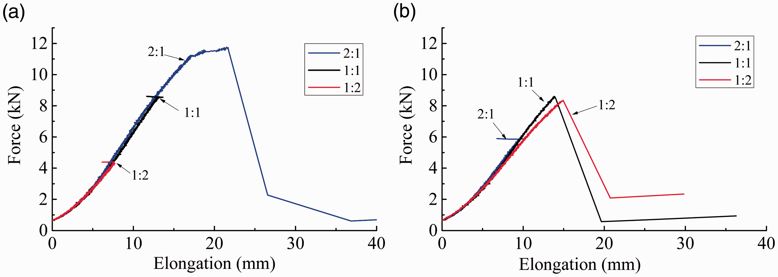
It can be seen from Figure 4(a) that when specimens are subjected in the 1:1 or 1:2 load ratio, the crack will propagate and rupture perpendicular to the weft yarns. Two reasons can have a legible explanation on such phenomenon. One is that the initial crack was introduced in the weft yarns. The other is because the ultimate tensile stress of the weft yarns is lower than that of the warp yarns for such new textile. Hence, the crack will propagate along their initial fragile direction, i.e. the weft direction. However, a catastrophic failure emerged on the warp branches before weft crack propagated for specimens under 2:1 load ratio, see Figure 4(b). Such phenomenon occurs because the warp yarns endure double load than the weft yarns during 2:1 load ratio. In the end, the warp yarns reached their maximum tensile force before the remaining weft yarns, and turned out to be ruptured on the warp arms.
From Figure 5 it can be seen that the slopes of force–elongation curves have good consistency, reproducibility and stability in both warp and weft loading directions. That is to say, the load ratio shows insignificant effects on the elastic modulus of the textile with identical initial crack. However, two types of graphic endings are observed in the force–elongation curves. One ends in a short horizontal line whereas the other emerges a sharp decline at the top point and then a slightly ascent in the end. Generally, the horizontal line demonstrates that yarns can sustain more force. However, the abruptly declined line indicates that catastrophic fracture occurred. For instance, the warp yarns of specimen in 1:2 load ratio can endure more force; however, the weft yarns of such specimen have reached to their peak value, see the red line in Figure 5. Hence, it can be deduced that the specimen ruptured in the weft yarns when sustained in load ratio 1:2 and 1:1, whereas failure occurred in the warp yarns when the specimen sustained in 2:1 load ratio.
It is generally known that an airship envelope can be approximated to a cylinder in the vicinity of the midsection [5]. Hence, the simplified load ratio between the longitudinal and hoop yarns of a specific airship capsule is 1:2. Figure 5 reveals that the rapture of the cruciform specimen under 1:2 load ratio occurred in the weft direction. Such phenomenon manifests that the weft yarns of GQ-6 exert their total mechanical property with a certain crack. In other words, the new envelope fabric is capable to be applied to no-rigid airships.
Additionally, the maximum forces of weft yarns for specimens in 1:1 load ratio are nearly approximate to that of specimens in the 1:2 load ratio. That is to say, the weft yarns have exerted their ultimate load during the above-mentioned load ratios. However, the force of warp yarns for specimen in the 1:2 load ratio manifests a lower force than that of specimen in 1:1 load ratio. In other words, the warp yarns of specimens in the 1:2 load ratio hardly express their mechanical properties. To study the mechanical properties of GQ-6 thoroughly, the load ratio of 1:1 is optimized to discuss the other two factors in the following sections.
Effect of initial crack length
Layout of the cruciform specimens with various initial crack lengths.

It is observed in the experimental process that all the cracks propagate along the initial crack orientation. Meanwhile, there is almost no tear propagation and all the catastrophic failure occurred suddenly. Such phenomenon is not similar to another plain-woven polyester fabric coated with a PVC matrix, whose fracture emerged in two types, i.e. one’s crack progressively propagated to the end whereas the other’s failure emerged suddenly. There is no exclusive rupture type for all the woven fabrics. The above-mentioned difference is due to the specimen sizes and the disparate yarns for various woven fabrics.
To detect the tear mechanical properties of such envelope, the force–elongation curves of a typical group of specimens with cracks in the weft yarns are selected and shown in Figure 6.
Initial crack length influence on cruciform specimens. (a) The warp direction curves and (b) the weft direction curves.
From Figure 6, apparently, the maximum forces of the specimens decrease rapidly as the initial crack length increases. The direct reason for such phenomenon is the number of ripped specimens of the residual yarns reduced with the increase of crack length. Similar testing results also emerged in Luo and Hu’s [11] multi-axial tearing test and Bigaud et al.’s [10] uniaxial and biaxial tearing tests. It is found that the slopes of the force–elongation curves present high reproducibility in the intact yarns (see Figure 6(a)), and the identical specimens rather demonstrate a reduction in the deficient yarns (see Figure 6(b)). Therefore, the initial crack length has an incredible influence on the mechanical properties of textiles.
Generally, as for the tearing tensile tests, the critical tear tensile stress of the woven fabric is always the foremost. To make a clear illustration on the tearing characteristics of such envelope, the critical tensile stresses between the uniaxial and biaxial tearing tests with identical initial crack lengths and oriented at 0° were plotted, see Figure 7. The critical stress of the textile under uniaxial tests is referenced to our previous paper.
Comparison of critical stresses between the uniaxial and biaxial tests. (a) The warp direction specimens and (b) the weft direction specimens.
As can be seen from Figure 7, many similarities were observed between the uniaxial and biaxial mechanisms. The initial crack of cruciform specimens also takes an elliptic shape during loading. The critical tensile stresses of specimens decline drastically with the increase of the initial crack length. However, the critical stress values of the ripped textile under biaxial tension are higher than that of textile under uniaxial loading. Nonlinear tear mechanical properties of the textile under biaxial tension are more obvious. Such phenomenon is due to the complex constraints on the warp and weft yarns under biaxial tension.
Effect of crack orientation
Layout of the cruciform specimens with various crack orientations.

After thoroughly observing the tested specimens, two fracture modes were distinguished for the textile during biaxial tensile load according to the crack orientation:
For a crack orientation lower than a certain threshold θ, this fracture mode is described as “warp yarns propagation” mode: after the first yarn in the vicinity of the crack tip ruptured, the crack propagates along the warp yarns until failure emerged abruptly, see Figure 8(a); For a larger crack orientation, the corresponding fracture mode is described as “weft yarns propagation” mode: the initial crack propagates along the weft yarns, see Figure 8(b). Typical fracture modes of the cruciform specimens with various crack orientations. (a) Crack propagation on the warp yarns and (b) crack propagation on the weft yarns.

The above-mentioned fracture modes are unlike the uniaxial tests, where crack propagation always occurred perpendicular to the loading direction.
Fracture modes of cruciform specimens in various initial crack orientation (30 mm, 1:1).

Form Table 5, apparently, the crack orientation limiting the above-mentioned two fracture modes is between 30° and 45° for the GQ-6 envelopes, when subjected to the load ratio 1:1.
However, other researchers have revealed different modes of crack propagation for various fabrics [5,10,18]. Some found that yarns will break on the warp or weft direction, no matter what the initial crack orientation is. But others found that the crack propagation will change the rupture direction which is similar to the GQ-6 textile. Theoretically, the above-mentioned difference correlates to the various fibers and weaving progress applied during operation. Specifically, yarn classifications, the amount of yarns in the warp and weft direction, respectively, the number of layers, the adhesives applied during splicing, etc. Therefore, there is no definite crack propagation for wide varieties of woven fabrics with identical crack orientation.
The evolution of the force for various crack orientations, with 30 mm initial crack length, is shown as Figure 8.
Form Figure 9, it is found that while the slopes of the force–elongation curves demonstrate homogeneity in the warp direction, the same fabric rather shows more fluctuations in the weft yarns. That is because the weft yarns are more sensitive owing to the weaving process. Hence, the weft yarns are hardly capable to collaborate very well and may represent more orthotropic and diversity. Further careful observation of force–elongation curves reveals that the maximum force enlarged but then decreased as the crack orientation increased.
Crack orientation influence on cruciform specimens. (a) The warp direction curves and (b) the weft direction curves.
To make a clear illustration on the maximum force fluctuation, the maximum forces of three specimens with identical crack orientation are averaged and given as Figure 10. The abscissa axis is defined by initial crack orientation, i.e. the intersection between the crack and the weft yarns. What should be noticed is that only the warp yarns’ maximum forces are plotted in Figure 10 since the cruciform specimens may own identical maximum forces subjected to a load ratio of 1:1.
Relationship of the maximum force and crack orientation of cruciform specimens.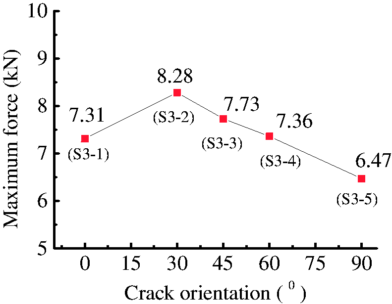
Form Figure 10, apparently, the maximum tear force of the new textile with 0° crack (only warp yarns cut) is higher than that of GQ-6 with 90° crack (only weft yarns cut). That is due to the structural uniformity of the yarns’ density and regularity. Another interesting phenomenon is that the maximum force will be enlarged as the crack orientation getting larger, no matter the fracture mode is the “weft yarns propagation crack” or the “warp yarns propagation crack”. Therefore, cracks inclined to the axis of the textile are less critical than those of equal length parallel to the natural axis for GQ-6.
Experimental determination
Three theoretical simulations
According to the researches of the Results and discussions section, the new textile with cracks paralleling to the natural axis exhibits the least critical tear stress. Therefore, the specimens with in-axial initial cracks, belonging to the mode I, were exclusively considered to determine the critical energy release rate and the toughness of GQ-6. The Thiele’s empirical theory has been proved to be acceptable for researching the tear propagation characteristics of the airship envelope fabrics [5], and therefore, the corresponding parameters of such empirical theory are also estimated below.
The critical energy release rate was determined by the Griffith theory, which based on the energy balance theory. Such theory is capable to be applied in the infinite flat. Considering the size of cruciform specimens is sufficiently large compared to the initial crack, therefore, it is appropriate to ignore the boundary effects. The critical energy release rate GIC is shown as follow
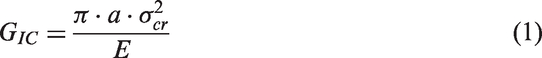
After substituting the experimental data to equation (1), the corresponding values of GIC are 29.15 and 22.22 for the cruciform specimens ruptured in the warp and weft directions, respectively.
The toughness KI can be deduced by the stress intensity factor theory. Such theory depends on linear elasticity fracture mechanicals, and KI is given as


After confirming the FT for each specimen by substituting the experimental data to equation (3), the toughness KI is calculated to be
The Thiele’s empirical theory has been successfully applied on the Zeppelin airship envelope materials [5]. The general form of such theory is shown as follow

For the flat specimen, the above equation can be simplified as

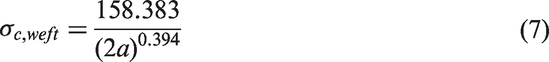
After substituting the experimental data to the above equation, the relevant functions for the specimens ruptured in the warp and weft direction are obtained

Crack equivalent length
According to Bigaud et al.’s [10] tearing tensile experimental results, the research on textile with off-axial cracks results in a study on fabric with in-axial cracks by introducing the concept of crack equivalent length. It has been testified that the crack equivalent length is capable to be applied to GQ-6 during uniaxial test in our previous paper [12]. However, it seems that the validity of the new concept on GQ-6 under biaxial load is more important for an airship, considering that an airship’s mechanical behavior of structure is approximated to be in the biaxial tension [5]. Therefore, the crack equivalent length was introduced to the biaxial tearing tests.
The crack equivalent length is obtained by projecting the initial crack length in an axis paralleled to the loading direction. When a specimen is subjected to uniaxial load, the crack equivalent length is shown as equation (8)

Layout of the complementary cruciform specimens ruptured in the warp yarns.

The relationship between the crack equivalent length and critical tear stress of specimens.

As can be seen from Table 7, apparently, the direction on which to be projected is of importance to analyze the tear propagation accurately. Meanwhile, the critical tear stresses of the warp yarns are still higher than the weft yarns on the defective envelopes.
Now the three theoretical simulations described in the Three theoretical simulations section are applied to detect how well they correlate with the experimental data, see Figure 11.
Comparison of the experimental data and theoretical simulations for various fracture modes. (a) Specimens of warp yarns propagation mode and (b) specimens of weft yarns propagation mode.
From Figure 11, obviously, all the experimental data are in good accordance with the above-mentioned three theoretical simulations. Therefore, the crack equivalent length is also proper to be applied for GQ-6 during biaxial tearing tensile condition. That is to say, by introducing such concept, the correlation between the critical stress and an arbitrary crack can be translated to the relationship between the critical stress and in-axial crack for GQ-6.
Allowable crack length
It is generally believed that an airship may generate a crack with arbitrary crack orientation due to complicated working conditions. According to FAA-P-8110-2 [19], Airship Design Criteria, the crack must not propagate under the limit load condition. The planned technology demonstrator of a stratospheric platform is 195 m long, and the maximum diameter is 33.75 m. If the limit stress of the GQ-6 envelope fabric is assumed to be 30 N/mm during working condition, the limit crack length above which the tear propagates is 57 mm, 52 mm and 50 mm obtained by the Griffith theory and the stress intensity factor theory, and the Thiele’s empirical theory, respectively. The graphical presentation is shown in Figure 12. Considering the safety factor, the technology demonstrator of crack length for GQ-6 material is determined as 50 mm. Such a threshold value is slightly higher than 48 mm, which we obtained from the uniaxial test [12]. That was because there is more tension homogeneity of the yarns during biaxial loading than that of under uniaxial tension. However, it is acceptable for projectors because the difference between the two threshold values is tiny. Comparing the threshold value of the Zylon envelope material [5], whose technology demonstrator can withstand around 40 mm, the tear mechanical properties of the new envelope fabric is excellent.
The allowable crack length for GQ-6.
As shown in Figure 13, the yarn direction will translate to be oblique due to the shear stress caused by the stress concentration near the crack tips. Meanwhile, the yarns of the envelope fabric in the vicinity of the crack will protrude due to lack of circumjacent restraint. Therefore, a crack in the airship envelope is detectable, and an initial crack smaller than 50 mm can also be detected.
Peripheral appearance of the crack.
Conclusions
In the present work, the tearing mechanical behaviors of a new envelope fabric for airships, GQ-6, are successfully identified by biaxial tensile tests. The following concluding remarks can be drawn:
The crack propagation direction changes under different load ratios. When the load ratio of warp to the weft is 1:1 or 1:2, the cracks will propagate along the weft yarns, while they propagate along the warp direction when subjected to load ratio of 2:1. The maximum forces of the textile decrease with increase of the initial crack length, especially when the crack length is larger than 30 mm. Meanwhile, the tear mechanical performance of the GQ-6 in the warp direction is better than that in the weft direction. Two fracture modes were observed, e.g. either along the warp or the weft yarns directions, which depends on the value of crack orientation. The threshold value distinguishing the two modes was found out to be at 30°–45°. Cracks inclined to the axis of the textile are less critical than those of equal length parallel to the natural axis. The critical energy release rate and the toughness for GQ-6 have been evaluated. The GIC is 29.15 and 22.22 in the warp and weft directions, respectively. The KIC is determined as The reduction in the tear strength of GQ-6 is capable to be characterized by the crack equivalent length during biaxial tensile condition. The allowable crack length for the GQ-6 is estimated to be up to 50 mm during the working condition.
Footnotes
Declaration of Conflicting Interests
The author(s) declared no potential conflicts of interest with respect to the research, authorship, and/or publication of this article.
Funding
The author(s) disclosed receipt of the following financial support for the research, authorship, and/or publication of this article: The authors would like to acknowledge the 46th Research Institute, 6th Academy of China Aerospace Science & Industry Corp. for the GQ-6 materials support of the research work.