
Abstract
The high-performance fibres are employed largely as reinforced polymer fabrics and composites in the flexible and stiff stab-resistant personal protection equipment. To simulate the knife attack on the human body, a new methodology named pre-deformed stabbing is developed to characterise the stab performance taking into account the fabric’s deformations. Three-dimensional warp interlock fabrics (3DWIFs) were manufactured using high-molecular-weight polyethylene (HMWPE) yarns. The forming was performed on the tested 3DWIFs before the stabbing. The stabbing results are influenced by the different mode deformations created during the forming. Based on the in-plane shearing map, three different stabbing locations were chosen. The effect of locations on the stab resistance of 3DWIFs was explored with the same impact energy level. The effect of stabbing localization on the deformed fabric is significant. The shear-locking angle in the location area is critical for the stab resistance of both [0°/90°]8 and [0°/90°, −45°/45°]4 deformed fabrics in the studied cases.
Introduction
In recent years, with strict controls over the use of guns, violent attacks using sharp weapons, such as knives, have become the most common instruments used to carry out terrorist attacks. 1 For knife and spike attack, additional or different packs are used which contain various ‘stiffer’ materials like laminated fabrics or metallic elements. A group of body armour materials for stab and spike protection have been reviewed recently. 2 To ensure effective protection from typical handguns and small, lower speed shrapnel fragments, soft body armour, commonly used by both police and military, must be adapted for the shape of the human body.3,4
Despite the growing trend of females joining the law enforcement police and military services across the world for the last few decades, they still use the body armour designed for males. The differences between the female body armour and male body armour lie in the curvaceous shape of the female body resulted in the problems in the manufacturing process. 5 The dangers from stab impact for females are particularly acute in the case of female breasts. Breast, or mammary, tissue is easily injured and heals slowly. Injury often results in necrosis or death of the mammary tissue, which is eventually replaced by lumpy scar tissue. 6 Beyond possible disfigurement, breast injuries can result in the loss of a breast and even hurt the heart. The current methods used in making female body armour include cut-and-sew techniques, overlapping, moulding, angle-interlock, and three-dimensional (3D) seamless knitting technologies,7–10 that some methods also have disadvantages. For example, cutting and sewing techniques can have negative consequences because seams can be created by the stitches needed for producing the contour of female breasts and overlapping seams may allow small projectiles to impact directly at the seam edge and penetrate the fabric. 10 Therefore, it is necessary to increase protection and improve comfort of female body armour. 11
In terms of soft body armour, woven fabrics are still very popular since they conform extremely well and provide maximum levels of comfort. 12 A soft body armour vest used today consists of multiple layers of fabric, that can be more than 30 layers to form the final body armour pack or vest based on the protection level required, to protect the upper torso for both male and female users. 13 Soft armour systems for military personnel are reported with the drive for lighter, and therefore smaller, 12 which are the challenges for armour designers. Advanced body armour technologies aim to reduce body armour vest weight.14,15 Li et al. 16 studied the dynamic stab resistance of multi-ply three-dimensional warp interlock fabrics (3DWIFs) for protective applications. Besides, they also studied the impact performance of 3DWIFs in double and multi-angle pass stabbing. 17 A recent review of soft body armours is highlighted by Arora and Ghosh 18 that adding shear thickening fluids has become popular. While Crouch 12 suggests in the review that any claimed benefits of shear-thickening fluids require deeper scrutiny. Besides, many protective clothing has only front and back pieces for protecting the breast and back, respectively, 19 which is relatively weak in protecting the human shoulder. Once the shoulder is injured, further injury is hard to prevent. These body parts, like the female breast and shoulder, have special and more complicated shapes that are particularly critical and important in protection.
Forming, as a commonly used technique, is helpful to achieve a required complex shape of dry fibre textile preforms, which is suitable for moulding the human shoulder or female breast in the application of body armour without applying any kind of cutting and stitching. There is great potential for some traditional textile methods to be properly utilized in modern soft body armour through new design and engineering methods. As shown in Figure 1, Teijin Aramid in collaboration with Triumph International claims the concept of manufacturing the women’s body armour via the moulding process with the aid of pressure and heat on the two-dimensional (2D) woven p-aramid (CT709) fabric to create the moulded panels.
20
Female body armour by the moulding process.
20

However, stab resistance of female body amour is rarely studied in the literature. Several studies have emphasized on ballistic female body amour. Hussein et al.
21
invented the functional materials of multi-layer woven laminated to substantially conform to the women’s frontal body morphology by the moulding process. Figure 2 shows a multi-layer woven laminate for ballistic and impact-resistant protective wear in sectional or component form. Chen et al.
5
showed that angle-interlock fabrics can be used for making ballistic female body armour after forming a dome shape. Abtew et al.
22
show that 3DWIF shows better shaping ability according to the female contour while designing the ballistic body armour than its counterpart 2D plain weave p-aramid fabric. Therefore, it is essential to provide fit, comfort and protection with stab resistance for women who engage in military, police and prison work. A multi-layer woven laminate for ballistic and impact-resistant protective wear in the sectional or component form.
21
The conventional single-pass stab resistance of different structures of 3DWIFs has been discussed in the study, 16 which proved that orthogonal-through-the-thickness (O-T) interlock structure has a good stab resistance under the same experimental conditions compared with other structures. In this study, a novel test has been proposed, named the pre-deformed stab-resistance test, which is conducted to simulate some parts of the human body wearing body armour, for example, female breast or shoulders, are attacked by stabbing. Besides, the comprehensive deformation behaviour of the single O-T interlock ply in different orientations ([0°/90°] and [−45°/45°]) is to be examined with hemispherical forming devices. The influence of the shear angle on the stab resistance of fabric panels is investigated at different target locations based on the forming test result. Furthermore, the pre-deformed stab-resistance tests of the aligned fabric panels (fabric plies are simply superposed) and the angled fabric panels (fabric plies exhibit different angled orientation) in three different locations are also carried out and the experimental results are compared.
Experimental
Fabric preparation
General definitions of the 3DWIF used in research work.

Note: In 1U5D-3U1D2U, ‘U’ is up and ‘D’ is down.

Fabric structure (a) Cross-section weft yarns view and (b) 3D view.
The parameters of the fabric.

The schematic description of the different fabric ply types by two cutting methods with a single [0°/90°] ply and a single [−45°/45°] ply, respectively, as shown in Figure 4(a) and (b). The hemispherical forming tests of these two fabric plies were studied before the stab stage. The size of samples was 210 × 210 mm2 with the average thickness of 1.7 ± 0.1 mm which was precisely got using an electromagnetic sensor thickness measuring apparatus based on the standard NF EN ISO 5084. The warp and weft density were tested by cloth counter. The areal density values were measured according to NF EN 12127. Schematic description of the different fabric ply types by two cutting methods. (a) [0°/90°] ply (b) [-45°/45°] ply.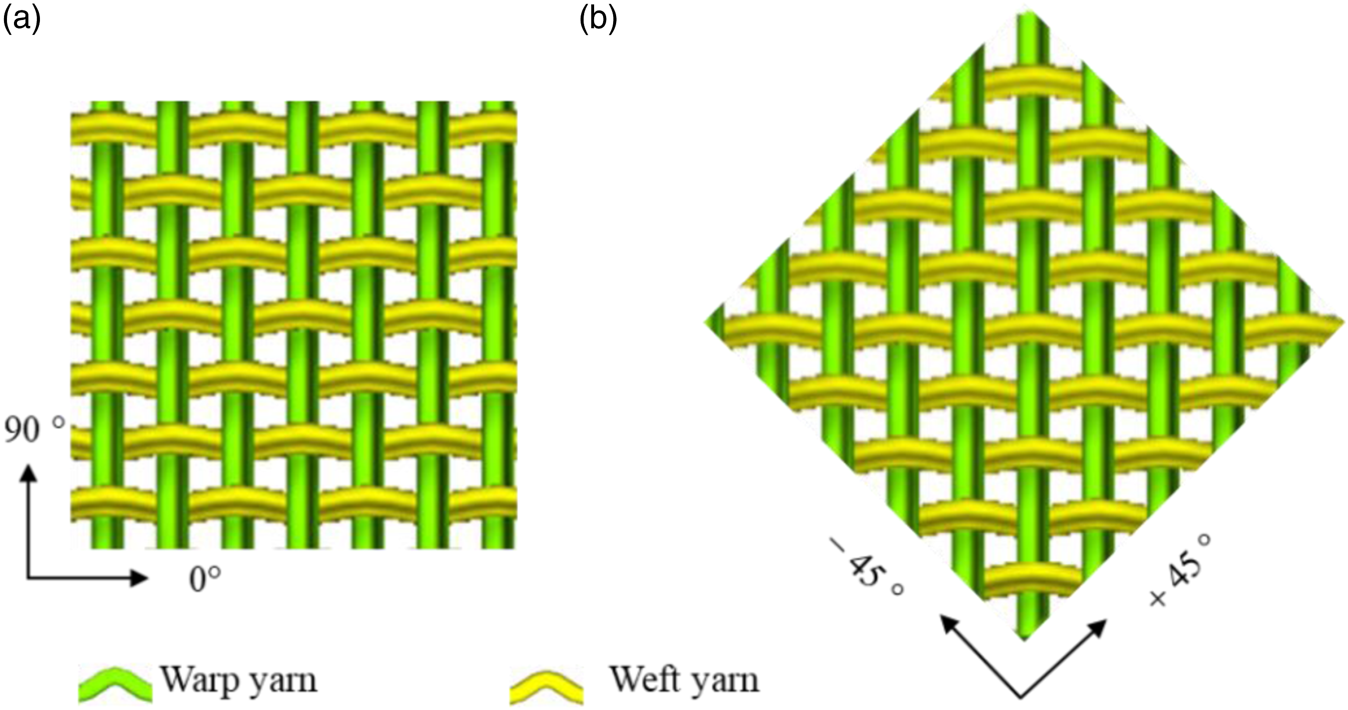
Two different types of sample panel systems have been prepared that each consisting of eight plies fabric with O-T structure, as shown in Figure 5(a) and (b), respectively. The aligned fabric panel was marked as [0°/90°]8. The fabrics of angled panel marked as [0°/90°, ±45°]4 were placed after rotating counter-clockwise direction from bottom to up. These different plies within the sample number of fabric panels were prepared without stitching yarns. Ply orientation in the specimens (a) aligned fabric panel and (b) angled fabric panel.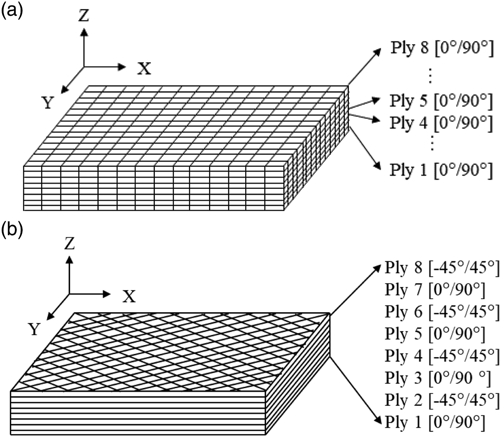
Testing
In-plane shear
The experimental bias-extension test was used to study the relationship between the shearing angle and load. The sample dimensions of the 3DWIFs must respect the geometric condition to achieve the measurement. Warp and weft yarn directions of 3DWIFs, (orthogonally fabrics) are orientated initially at 45° to the direction of the load. As shown in previous research,25,26 the initial length (H) (along the tensile direction) of the specimen must be more than twice the width (W) of the specimen. As illustrated in Figure 6, rectangular specimens of 210×70 mm2 were tested on MTS Criterion Testing Systems. The ratio of length (H) to width (W) is 3 in this study. Samples were clamped with a gauge length of 210 mm onto the machine that the warp and weft directions of the yarns are oriented initially at ±45° to the direction of the applied tensile force. These tests are performed at a constant speed of 50 mm/min until terminated at first sign of failure and repeated at least three times. The shear angle was measured directly by an optical measurement in the pure shear zone A during the test. Moreover, there is a limited shear angle, called ‘shear-locking angle’,
27
that the wrinkling will appear over this value.
26
The distance d between the two red points a and b from the same binding warp yarn is measured for determining the shear-locking angle. A rectangular specimen of fabric with a clamp area.
Stab resistance properties after deformation
Stab test apparatus
As shown in Figure 7, the test apparatus, which was adapted to the UK standard of HOSDB Body Armour Standard (2017),
28
was used for the stab resistance investigation. The stab experiments were carried out with the energy of 3.5 J (the drop height is 0.169 m and 2.11 kg in mass) by using HOSDB/P1/B sharpness blades with a total length of 100 mm, the cutting edge length of 33 mm, and the blade thickness of 2 mm.
29
The direction of the blade does not change during the test. Besides, Roma Plastiline® moulding clay was used as the backing material because it is cheap and readily available, and it attained higher deformation with time compared to other backing materials.
30
The container with Plastiline® clay was heated with 45°C in the oven for 5 h until the temperature reaches 37.5 ± 0.5°C before tests for imitating human body temperature. General view of schematic of a stab test device.
The stabbing depth was measured after the pre-deformed stab-resistance experiments. As presented in the study
16
and shown in Figure 8(b) and (c), the stabbing depth can be divided into two parts: the depth of penetration (DOP) and the depth of trauma (DOT) which shows the fabric depth of deformation. 3D scanning moulding is proposed by the 3D scanner in the present study to accurately measure and analyse the DOP and DOT (see Figure 8 (d)). Example of trauma shape and penetration depth of 6 plies F4 fabric stabbed by warp direction: (a) Preparation before stab test; (b) Figure to describe the DOP and DOT (b) Silicone mould; (c) 3D scanning moulding.
Testing procedures and methods
The pre-deformed stab-resistance tests are conducted to simulate the stabbing process of body armours, for example, female breasts or shoulders are attacked by stabbing. The experiments were tested on three different locations with the same energy level to study the effect of stab locations on the pre-deformed stab-resistance. Compared with the classical stab test, the pre-deformed stab-resistance tests were carried out with non-flat shape of the specimens on the same machine since many parts of the human body have certain radians rather than being completely flat, especially the part of female breasts.
As shown in Figure 9(a) and (b), the tested fabric panel prepared, with 0°/90° yarn orientation and the other with ±45° yarn orientation (Figure 4), was put in the centre between the upper transparent plate (with a round hole of 110 mm diameter in the centre) and the surface of the mould with a hemispherical groove. Then the fabric panel was stamped by the same punch with the same punching height (50 mm). For research purposes, to simulate the female breasts, we preferred to use a hemispherical shaped punch with a diameter of 100 mm to resemble the women’s body shape of average size ((90B) bra size). The forming process is finished by the mould directly. Then the pre-deformed fabric panel was stabbed with different locations, as shown in Figure 9 (c). As presented previously based on Figure 2, the locations will be selected based on the forming results for mimicking the injuries in different positions of the female breast by a knife blade. Each test was repeated three times. The steps of the experiment (a) Preparation of forming, (b) Forming (c) Pre-deformed stab resistance tests.
These testing procedures and methods were applied for the following reasons. The cloth on the human body is in a non-clamped state, to be consistent with the actual situation and simulate the real stab attack, the edge of test samples were un-clamped for the pre-deformed stab resistance tests. Then there is the material deformation recovery after the forming process and some parameters will recover from its initial dimension, for example, punching height, material drawing-in, and in-plane surface shear angle. 31 Besides, it is easy for the fabric panel to keep the deformation with a hemispherical groove. Moreover, the influence of gravity is small in this case due to that the fabric is embedded in the groove after deformation. It can also reduce the possibility of damage when the samples were removed from the stabbing machine after forming. Also, this method shows the advantage when the thickness of the fabric panel was quite larger than the space between the punch and blank holder of the forming machine.
Besides, the pre-deformed stab-resistance experiments were divided into two parts, the first part focused on describing the deformation of [0°/90°] and [−45°/45°] single-ply, respectively. Comparisons were made by observing the resulting draw-in of the fabric and shear angles developed in the fabric after stamping. The second part focused on the stab resistance of multi-ply fabric panels at different locations after hemispherical forming tests. The locations were chosen based on the shear angle distribution, including the area with no deformation and with maximum deformation, and the in-between area. The same impactor and the same energy were used for tests.
Results and discussion
Shear-locking angle measurement
The shear-locking angle can be graphically determined by using these shear compliance curves suggested by Scouter.
32
Figure 10 shows the non-linear curve shear force against the shear angle which can be divided into three main stages. In the first stage (placing zone), the shear load is relatively small with a low slope and increases linearly until 20°, with the fibre rotating and moving freely. In the second stage (transitional zone), the external load increase sharply, and the fibre yarns begin to be in contact. In the third stage (locking),
33
the limit of the shear angle is reached. In these tests, the average critical shear angle is 30°. In the stage of the shear-locking angle, the yarns are in contact with their neighbours. When the shear angle exceeds the shear-locking angle, the yarns are subjected to gradually increased lateral compression due to the contact with their neighbours, which leads to the occurrence of wrinkles.27,34,35 Besides, the yarns can slip till breaking occurrence out of plane and yarns become far from the adjacent yarns. Graphical determination of shear-locking angle resulting from bias-extension tests.
The distance ‘d’ between the two red points is used for determining whether there is slippage before the shear-locking angle zone. Figure 11 shows the distance d of two red points at the macro-scale of the bias-extension test at the displacement of 0 mm and 31 mm, respectively. The distance d between the two red points has been measured by Image J software. It shows that the distance d remains the same during the period of 0–31 mm displacement. The shear angle is 30° at this moment that is not exceeded, which proved the shear-locking angle shown in Figure 10. The distance d of two red points at macro-scale of the bias-extension test at the displacement of (a) 0 mm and (b) 31 mm.
Deformation of the fabric panel
The material draw-in is a global characteristic exclusively for fabric deformability. It can be defined as the amount of material flow, along the contour, from the undeformed position to the deformed one during the draping process.
36
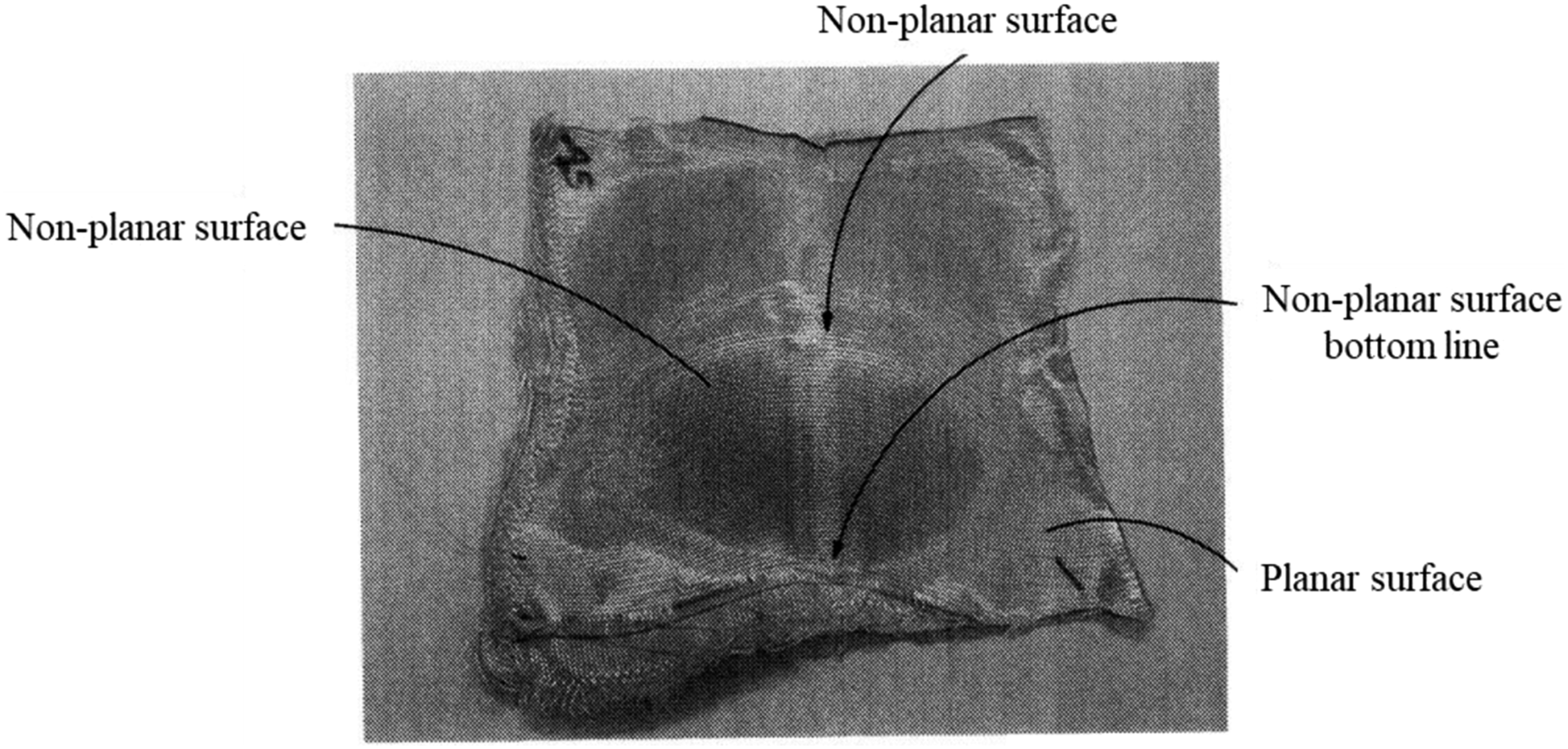
3DWIFs with [0°/90°] and [−45°/45°] ply orientation (Figure 4) were formed by a hemispherical punch with the same experimental conditions. The deformed 3DWIFs after the hemispherical forming test has been shown in Figure 12. Comparing Figure 12 (a) and (b), the two cases have quite different deformed profiles and local shear angle distribution, which proved that fibre orientations have a significant effect on 3DWIF reinforcements forming. The edges of [−45°/45°] yarn orientation samples expand outward, while for [0°/90°] yarn orientation samples, their edges contract inward. To quantify the formability, the material draw-in and surface shear angles by optical measurement were used to be the indicator of the extent of global deformation. Two types of deformed single-ply after hemispherical forming test (a) single [0°/90°] ply and (b) single [−45°/45°] ply.
In this section, as the pre-deformed fabric was approximately symmetric, the measurement data was obtained as the mean values of two diagonal sides and, for better accuracy, the same tests were repeated three times. Material draw-in of single [0°/90°] ply in the warp and weft directions are shown in Figure 13(a). The maximum value is slightly higher in the warp direction for a single [0°/90°] ply. Material draw-in of single [−45°/45°] ply in the warp and weft directions are shown in Figure 13(b), which has a completely different draw-in distribution in ¼ zone B compared with single [0°/90°] ply. Material draw-in in warp and weft directions of (a) single [0°/90°] ply and (b) single [−45°/45°] ply forming. (a) single [0°/90°] ply (distribution in ¼ zone A of the deformed ply). (b) single [−45°/45°] ply (distribution in ¼ zone B of the deformed ply).
Furthermore, the global shear angle distribution is compared. Shear angle, defined as the variation of the fibre intersection angle between warp and weft yarns, is one of the most important properties that determine how a fabric will behave when subjected to a wide variety of complex deformations. In particular, large in-plane shear could be necessary to obtain the required shape.
37
In this study, the data visualization was conducted using Matplotlib,
38
which is a 2D graphics package used by Python for application development, interactive scripting, and publication-quality image generation across user interfaces and operating systems. The distributions of shear angle are significantly affected during forming test and affect each other within zones of interest, as well as on a global scale. With the help of the data visualization method, the shear angle distributions after forming test of single [0°/90°] ply and [−45°/45°] ply, respectively, are obtained, as illustrated in the Figure 14(a) and (b). Woven fabric relies on shearing between weft and warp yarns to accommodate the large deformation needed in the forming process. It can be noticed that these shear angles are large along the diagonal line for [0°/90°] ply and the median line for [−45°/45°] ply. But along the median lines of 0°/90° and the diagonal lines of ±45°, the angular distortions are very small <8.5° and 5.7°, respectively. Comparison of the shear angle distribution of single-ply fabric after deformation: (a) [0°/90°] ply; (b) [−45°/45°] ply.
Wrinkles were found in none of the fabrics during the forming test. Nevertheless, the onset of wrinkling is related to achieving a critical shear angle. 39 In Figure 14 (a), the distributions of the shear angle on the symmetry line of the cross centre (weft and warp yarn directions) are minimum (less than 10°) and very smooth. Besides, the centre position is almost zero. Shear angles reach their maximums in directions of diagonal directions (±45° directions). There is no wrinkling within the main deformation zone C which has the largest shear angle distribution area compared with zone A and zone B. This is due to wrinkling that will occur when the shear angle exceeds the shear-locking angles 40 (around 30°), as shown in Figure 10. The maximum shear angle for the [0°/90°] ply is about 30.1° and 36.4° for the [−45°/45°] ply. Large gradients exist in the region of four corners for the shear angle distribution in Figure 14 (a). In Figure 14 (b), although the maximum shear angle is a little larger than the shear-locking angle, the wrinkles have not been found in the area with the largest shear angle. Because the wrinkle onset does not depend solely on the shear angle, the other strain energies also play a role 41 . Besides, the blank holders are shown in Figure 9 create tensions that decrease or suppress wrinkling in the useful part.
Stab resistance properties after deformation
Definition of stab location
As described in the Experimental section, the pre-deformed stab-resistance tests of 3DWIF panels are tested to resemble the stab of frontal female body contour. When a 3D female body armour fabric is stabbed by a knife blade, it may vary in results depending on the exact location of the stab. Each location corresponds to a particular yarn structure. The stab location, therefore, poses questions about the fabric behaviour in the 3DWIF stab impact. Based on the results of a hemispherical forming test of single [0°/90°] and [−45°/45°] plies, the pre-deformed stab-resistance test was conducted at three different locations on the deformed fabric panels with eight layers plies as shown in Figure 15. The shear angle of the vertex in the area of location A is around 2.2° of [0°/90°] ply and 0° of [−45°/45°] ply (see Figure 14). It means that, when the fabric panel in this area is stabbed, it is similar to the fabric panel stabbed on the flat fabric before deformation. As for location C (Figure 15(c)), it was determined because of, the largest shear angle (around 30°) of [0°/90°] ply and the location of the middle area B (see Figure 15 (b)) were determined because the distance is the midpoint place between the central location and locking angle area. In this section, the stab resistance of targets made of 3DWIFs with different target systems and target location conditions will be enlightened. The influence of the shear angle on the stab resistance of fabric panels will also be investigated. Schematic: (a) In the centre location, (b) In the middle area, and (c) In the locking area (dimensions in mm).
Pre-deformed stab resistance
In the stabbing experiment, the impact energy as mentioned earlier is lower than the required energy in the standards of personal protection analysis. To find out differences between the different structures fabrics, tests were performed under the energy of 3.5 J in this paper. The processes of aligned fabric panel of the pre-deformed stab-resistance tests from the top view are shown in Figure 16. To study the influence of fabric stacks on deformed 3DWIF panels, two different fabric patterns as shown in Figure 4, that is, [0°/90°] and [−45°/45°] plies, were chosen to form aligned fabric panel and angled fabric panel. The transparent glass, in Figure 16 (a), is used to assist the fabric panel to be deformed. For each panel, the pre-deformed stab-resistance tests of three stab locations, as shown in Figure 15, that is, in the centre location A, in the middle area B and the locking area C were employed. Example of the pre-deformed stab-resistance tests (a) Preparation, (b) Preforming of the fabric panel, (c) Stabbing on the deformed fabric panel, (d) Bottom of fabric panel after the pre-deformed stab-resistance tests.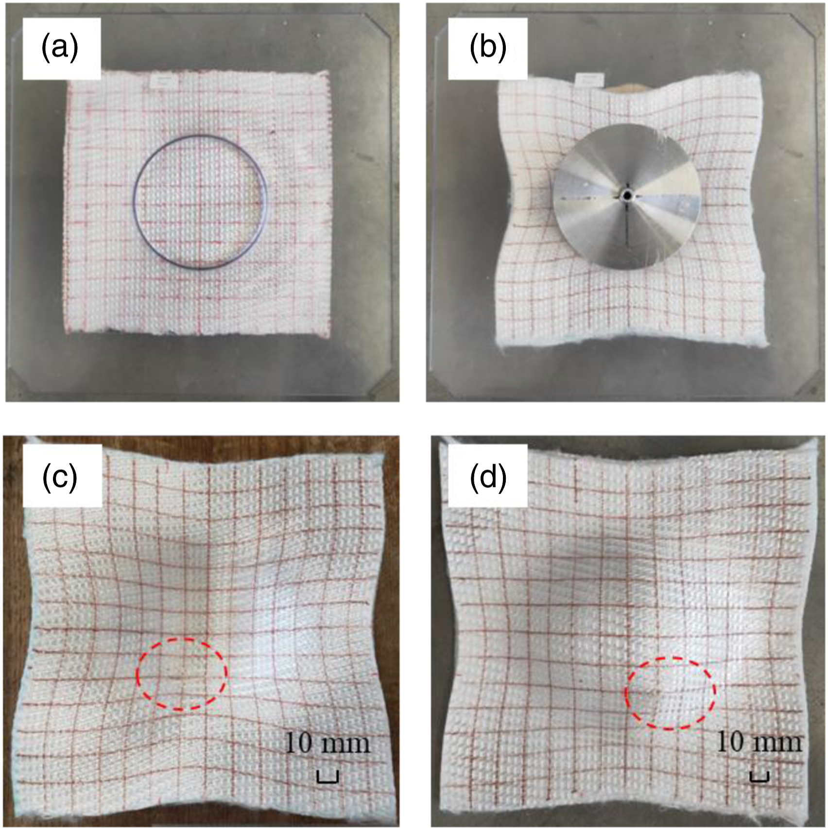
Influence of ply orientation
Average DOP value (mm) of aligned and angled fabric panels at different locations.


Depth of penetration (DOP) of aligned and angled fabric panels at different locations.
In the case of [0°/90°]8 aligned fabric panels, the DOP was decreased with the increase of shear angles in different locations, as shown in Figure 17. These results show that the centre location of aligned fabric panels is the most vulnerable position against stab. This may be because the increase of shear angle, to some extent, is helpful for the increase of fabric density, which can make more yarns more efficient for preventing the blade penetrate the fabric during the stabbing process.
In the case of [0°/90°, −45°/45°]4 angled fabric panels, although the shear angle in the location of C is small and near to 0° for single [−45°/45°] ply, it can be observed that the fabric which is stabbed in location C also has the minimum DOP value compared with other stab locations, as shown in Figure 17. It may due to that the weft yarn density is larger than warp yarn density. When the angle of fabric panels changed, more weft yarns will be cut by the blade. Besides, the angled fabric panels added the additional yarns in two directions (−45°/45°), which can reduce the possibility that the blade penetrated through the gap of the yarns. Moreover, concerning locations A and B of angled fabric panels, the former DOP value is smaller than the latter. It indicated that the stab resistance of the fabric in the middle location is less significant than that corresponding part in the fabric centre. Because the impact location of the fabric is near the edges, the extension of the deformed part along the tip of the knife is limited in the warp direction, and weft yarns are easily pulled out in its direction.
Influence of stab location
Figure 18 compares the damage morphologies of fabric specimen of [0°/90°]8 aligned fabric panels after the experimental stab test in different locations. Considering the partially enlarged view (Figure 18 (b)), the primary yarns (both weft and warp) in the back face of the fabric are cut by the sharp blade edges. All the fabric targets have been penetrated primarily due to fibre failure and all fabric panels show little or no evidence of windowing from the side view (see Figure 18 (c)). Besides, it is obvious that the stab damaged area of the fabric specimen stabbed in location C is much larger than that in locations A and B (see Figure 18 (b)). The improvement of the stab strength is mainly due to the shear-locking angle which is helpful to reduce the gap between yarns
27
in location C. As the fabric is deformed, the density of warp and weft yarns per unit area increases that prevent the knife from continuing to penetrate the fabric panel. Thus, the depth of penetration is the smallest. Besides, as shown in the side view in Figure 18 (c), it is clear to see that the yarns in location C are completely cut off by the sharp edge of the knife. The sample stabbed in location C appears to show a permanent, residual hole in the fabric layer that persisted when the knife was removed. By contrast, the sample stabbed in locations A and B shows no residual hole. While some of the secondary direction yarns in location A are pulled out and pushed as the knife penetrates.
42
It can be noted from the fabric specimen stabbed in location A and B that the deformation of fabric panels are smaller than the fabric specimen stabbed in location C (see Figure 18 (c)). Damage morphologies of [0°/90°]8 aligned fabric panels after the experimental stab test: (a) Overview; (b) Partially enlarged view; (c) Side view.
As shown in Figure 18 (c), the DOT value (26.3 mm) in location C is larger than the DOT value in location A and B which is almost zero. It indicates that the knife causes greater fabric deformation in location C compared with the cases in location A and B via stabbing with the same stab energy. Besides, it shows that most of the energy is absorbed by the fabric panel and, therefore, the DOP is smaller stabbing in location C. The reason is that the shear-locking angle appears in location C, which results in a tighter fabric panel and the yarns in this area can lock the knife and prevent the knife blade from perforating further during the penetration process.
Figure 19 displays the damage morphologies of fabric specimen of [0°/90°, −45°/45°]4 angled fabric panels after the stab test. During the stab tests, whether it was aligned or angled fabric panels, all the fabric panels were perforated, as shown in Figures 18 and 19. The local tearing strength of fibres is exceeded by the impact force, and therefore, the fibres are cut.
42
The fibres are not dishevelled and the cut is clear in locations B and C, see Figure 19(b). Besides, the samples stabbed by the knife in three locations appear to show a permanent, residual hole in the fabric layer after the knife was removed. The longitudinal fibres are mainly cut and transversal yarns are not completely damaged. It shows that the penetrator pushes the fibres aside without cutting them which was defined as a windowing mechanism by Mayo et al.
44
The fabric specimen stabbed in locations A and B has smaller deformation of the fabric panels than the fabric specimen stabbed in location C which is similar to the results shown in aligned fabric panels. Damage morphologies of [0°/90°, −45°/45°]4 angled fabric panels after the experimental stab test: (a) Overview; (b) Partially enlarged view; (c) Side view.
In Figure 19 (b), the trauma width in location A is smaller than the corresponding in location B. The first reason is that the yarns are highly symmetrical and evenly distributed in four directions (0°/90°/±45°) in angled fabric panels which can absorb more impact energy compared with the aligned fabric panel, which showed good agreement with the study of Wang et al. 33 The second reason is that the knife penetrated in the centre which is the point of intersection of yarn from four directions of the fabric panel. As shown in Figure 19 (c), in [0°/90°, −45°/45°]4 angled fabric panels, it is similar with the [0°/90°]8 aligned fabric panels that the DOT (18.5 mm) of fabric panel stabbing in location C is larger than the DOT stabbing in location A and B which is also around 0. It shows that the locking-shear angle is indeed, to a large extent, conducive to improving stab resistance.
Conclusion
An important research effort has been devoted to the understanding of the pre-deformed stab-resistance property of the 3D warp interlock fabric with O-T interlock structure after the hemispherical forming process to resemble the female body shape of 90B bust size. In-plane shear is the most important mechanical property for the forming behaviour of the fabric. Based on the analysis and discussion on the pre-deformed stab-resistance property of the 3D warp interlock fabric, the following conclusions can be drawn. (1) Two different initial orientations ([0°/90°] ply and [−45°/45°] ply) of fabric yarns were selected. Wrinkles were found in none of the fabrics during the forming test. It shows that the two cases showed quite different deformed profiles and local shear angles distributions. (2) Three different stab impacts locations were chosen based on the results of shear angles distributions. The pre-deformed stab-resistance property of aligned and angled fabric panels in three different locations was investigated and compared. The results show that the effect of stab localization on the fabric behaviour is significant. The pre-deformed stab-resistance of deformed fabric stacks [0°/90°]8 in the location with higher shear angle is better than in the corresponding part with lower shear angle for in the studied cases. (3) With regard to the deformed fabric stacks [0°/90°, −45°/45°]4, the result indicated that the stab resistance of the fabric in the middle location is less significant than that corresponding part in the fabric centre.
In the future work, analyses of the test results suggest that the pre-deformed stab-resistance property is the combination of several deformations, including formability, shear property and stab resistance property. The new test method can help explore better female body armour with comfort, flexibility, fitness and good stab resistance.
Footnotes
Declaration of conflicting interests
The author(s) declared no potential conflicts of interest with respect to the research, authorship, and/or publication of this article.
Funding
The author(s) disclosed receipt of the following financial support for the research, authorship, and/or publication of this article: The authors would like to acknowledge the China Scholarship Council (Project no. 201708420167) and the Philosophy and Social Science Planning Project of Guangdong Province (No. GD20CYS14) for supporting this research.