
Abstract
Fabrics constructed from 3 D warp interlock fabrics (3DWIFs) structures provide varying flexibility and durability and are promising structures for protective applications. However, its performance toward stab resistance from knife attack should be investigated before applying. In this work, the influences of fabric architectures, ply orientation of stacking sequences, and the number of fabric plies on the dynamic stab resistance are comparatively studied on high-molecular-weight polyethylene (HMWPE) 3DWIFs. It indicates that 3DWIF with orthogonal and through-the-thickness interlock structure reveals a helpful influence on stab resistance. Further investigation on the influence of different ply orientation of stacking sequences, based on the combination of fabrics placed at different angles, is analyzed showing a certain influence of stab resistance. Dynamic stab resistance reveals the linear correlation with a low number of fabric plies (less than 6 plies), but shows a parabolic relationship with the increase of fabric plies (more than 16 plies) until there is no penetration.
Introduction
Flexible, comfortable materials are required for a range of applications, including protecting law enforcement and security personnel against stab attacks. These soft materials that will help make the protective clothing functional by improving the range of motion and reducing fatigue. Due to the restrictions imposed by firearms control legislation and more commonly used of knives in street fights and muggings [1], stabbings are still a persistent and worrying concern and growing life-threatening assaults to the policemen and security forces are of particular concern in European and Asian countries [2,3]. Recent trends have led to an increase in the number of applications, such as protective gloves, law enforcement, and security personnel body armor, firefighter protective suits, and inflatable structures, which require stab-resistant property [4,5]. Many researchers have mainly attached importance to studies about stab resistance of soft body armor, ranging from an experimental investigation of stab resistance property [6–9], analytical model finite element method (FEM) [10] and the shear thickening fluid (STF) treatment [11]. Research on stab-resistant personal protective equipment (PPE) has been highly concentrated on flexible PPE based on the STF and fabric laminates, including numerical simulation [10,12] and experimental analysis [10,13–21].
In all these studies, the materials selected to manufacture the fabrics or preforms are almost high strength and high modulus fibers which promotes the development and innovation of the manufacture of soft body armor. There are some commercial fibers, characterized by their stiffness and strength-to-weight ratios, has been widely used for stab resistance fabrics, including aramids such as Twaron® (Teijin), Kevlar® (DuPont), and ultra-high-molecular-weight polyethylene (UHMWPE) such as Spectra® (Honeywell) or Dyneema® [22,23]. High molecular weight polyethylene (HMWPE) fibers are known for their low density (0.97 g/cm3), high fracture strain (3%) and excellent energy absorption capacity, which makes them one of the top choices for body armor [24,25].
These high-performance yarns can be used to produce high-strength textile fabrics, includes two-dimensional (2 D) and three-dimensional (3 D) fabrics [23], with good stab resistance and flexible geometry which can make them be favorable materials for both military and Personal Protective Equipment (PPE), such as body armor or helmets. Conventional stab-resistant vests are made of 20–50 sheets of multiple layers of p-aramid or UHMWPE fiber fabrics [26] because, in general, a single layer of high-performance fabric is incapable to protect the victims from knife attacks. Hence, it is inevitable to bind multiple fabric layers together by adhesion or stitching for structural integrity to prevent delamination. This extra adhesion or stitching process increases the stiffness of the fabric assembly which reduces the mobility of wearer [25]. Besides, the process of stitching deteriorates the yarns (i.e., needle piercing through the yarns) [27]. While, in 3 D warp interlock fabrics (3DWIFs), layers are connected together by a binding yarn to ensure greater cohesion [28], preserving the integrity of the entire structure. Besides, 3DWIFs revealed good mouldability and fewer wrinkle formations as well as other good mechanical properties [29], which can also be used as female body amour [30].
Stab resistance of the fabrics is generally attributed to various factors, including its structures, yarn crimp, and several mechanisms of energy absorption and dissipation of the fabric [23]. Weaving design has been identified as one of the major factors which influence the mechanical properties and stab resistance of fabrics. Arora and Ghosh [31] collectively summarized the various parameters which contribute to the impact performance of soft armor panel. These parameters have been classified into four categories: material parameters, structural parameters, projectile parameters, and testing parameters. However, few kinds of researches have been carried out on the influences of weaving design (structural parameters) of stab resistance, especially for 3 D structures fabrics [29]. In other words, most of the research still emphasizes the structure influence of stab resistance based on 2 D fabrics. For example, Wang et al. [32] indicated that the structure affected the quasi-static puncture resistance property of the fabrics, the plain fabrics had better puncture resistance property than twill and satin fabrics. There are four main categories, Angle-Through-the-thickness interlock (A-T), Angle-Layer-to-layer interlock (A-L), Orthogonal-Through-the-thickness interlock (O-T), Orthogonal-Layer-to-layer interlock (O-L), of the structure of 3DWIFs as mentioned in Boussu et al. [28]. Besides, there is less research about the effect of ply orientation on the stab resistance. An experiment, for instance, was conducted by Messiry and Eltahan [7] to study the effect of the weave construction (tri-axial and 2 D plain-woven fabrics) on the puncture resistance of the fabric. There was a marked difference in performance between the 2 D plain-woven and tri-axial woven fabrics, which proved the advantage of tri-axial weave fabrics over the other types of weave. Moreover, most research studied the relationship between numbers of fabric plies and the dynamic stab resistance in the case of penetration [7].
This research aims to investigate the dynamic stab resistances of 3DWIFs structure with high-performance HMWPE yarns for protective applications. Experimental studies on the stab resistance of 3DWIFs are performed to provide evidence regarding the damage on the fabrics. Five different structures were fabricated according to the four main categories of the structure as mentioned above. The present study focused on investigating the effect of 3DWIFs architectures, ply orientation of stacking sequences, and the number of fabric plies on dynamic stab resistances of the fabrics that are prepared with HMWPE yarns.
Materials and methods
Materials
Five woven samples of 3DWIFs with different design structures were manufactured with HMWPE yarns which are described as follows; 1350 dTex, “Z” type twist, and 50 twists per meter. A-L 3-2 4 Binding {Twill 4 effect left}-Stuffer (F1 fabric) O-L 3-2 4 Binding {Twill 4 effect left}-Stuffer (F2 fabric) A-L 5-3 4 Binding {Twill 6 effect left}-Stuffer (F3 fabric) O-T 5-4 4 Binding {Twill 6 effect left}-Stuffer (F4 fabric) A-T 5-4 4 Binding {Twill 6 effect left}-Stuffer (F5 fabric).
where A-T is Angle-Through-the-thickness interlock, A-L is Angle-Layer-to-layer interlock, O-T is Orthogonal-Through-the-thickness interlock and O-L is Orthogonal-Layer-to-layer interlock. The weaving was carried out on a Dornier dobby loom at a speed of 75 picks/min. For all the fabrics, the thickness test and the mass per unit area have been measured according to the standard NF EN ISO 5084 [33] and NF EN 12127 [34] respectively. The geometrical structure parameters of five tested fabrics are shown in Table 1.
The structure parameters and specifications of five 3DWIFs.

Dynamic stab resistance test
The stab resistance test of the 3DWIFs specimens was conducted by a drop tower impact test machine (Figure 1) according to the UK standard: HOSDB Body Armor Standard (2017) [35]. A series of stab experiments with the energy of 2.5 J, the drop height 0.121 m and 2.11 kg in mass were carried out, with HOSDB/P1/B sharpness blades which have a total length of 100 mm, the cutting edge length of 33 mm, and the blade thickness of 2 mm [16]. Note that this energy is lower than that considered in the standards of personal protection analysis; this is because, in this work, the multiple plies of 3DWIFs are analyzed under low-velocity stab test and not a real vest. Likewise, 100 × 100 mm2 samples were unclamped on the backing materials of Plastiline® container with a 140 mm diameter. Three times of stab tests were carried out for each specimen.
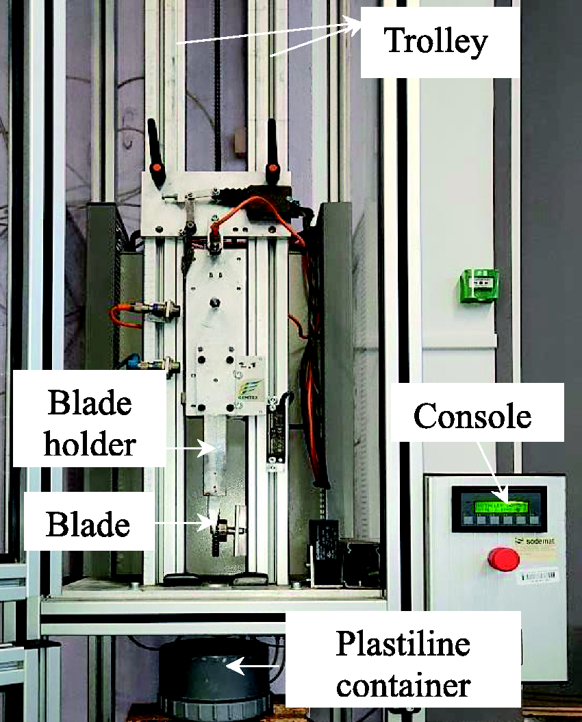
Stab test device.
The unclamped specimens were stabbed in the center of the sheets, as the schematic shown in Figure 2. The ply orientation of the fabric panels (angle α) can be described by X (0°), Y (90°), Z orthogonal coordinate system, which depends on the angle α formed by the fabric rotating counter-clockwise and X-axis (weft yarn direction), (Figure 2(a) and (b)). Wang et al. defined that [36], when all the plies (all warp yarns in the fabric panel) are in the same direction, the panel is defined as aligned fabric panels. When the panels are oriented in different directions, the panel is defined as an angled fabric panel. As shown in Figure 2(a) as an example, the schematic of four-ply fabric panel was made up of four single-ply 3DWIFs. When the blade is parallel to the weft yarn in four plies aligned fabric panels, the stab angle is 0° and it was marked as [0]4 as shown in Figure 2(a); on the contrary, when the blade is parallel to the warp yarn, the stab angle is 90° and it was marked as [90]4. The panels are oriented in different directions like [0/22.5/45/67.5], as shown in Figure 2(b). For aligned fabric panels, the fabrics are stacked counterclockwise from the bottom to up with incensement of the number of plies. In this study, single and multi-plies of 3DWIFs are prepared and laminated as aligned stacked fabric panels and angled stacked fabric panels.

Schematic of the coordinate system of the ply orientations panels for the stab test: (a) aligned panels [0]4; (b) angled panels [0/22.5/45/67.5].
The measurement of the depth of penetration
The depth of penetration (DOP) caused by the stab can be measured by the compound of silicone and catalyst at the ratio of 20:1 [37]. The RTV 181 poly-condensation silicone with a density of 1.25 g/cm3, which is a very resistant elastomer, was used to recover prints of the complex shapes of the blade into the Plastiline®. The silicone compound was filled into the Plastiline® container to obtain the silicone prints of fabric deformation. The DOP, defined as the distance between the top tip and the surface of the fabric print mark in the silicone mould, can be measured based on the obtained prints (see Figure 3(a)). The surface damaged area, as shown in Figure 3(b), can be measured and compared based on the silicone prints directly. Moreover, the stab resistance was determined by the DOP of the blade impactor beyond the 3DWIFs. A lower penetration depth represented a better stab resistance [16].

Examples of silicone print. (a) Definition of DOP; (b) Surface damaged area of silicone print.
Results and discussion
Effect of fabric design on stab resistance
Figure 4 shows differences of the DOP among the five architectures and different laminated plies against the knife (P1) impactor with impact energy of 2.5 J and the stab angle is at 0°. In terms of the one-ply [0] fabric stab tests, the DOP are almost equal to each other and approximately equal to the length of the exposed blade. Because the blade completely penetrated the 1-ply fabrics until it was stopped by the handle, which showed that the stab resistance of single-ply fabric is not enough under this impact energy. Moreover, in terms of stab tests of three-ply [0]3 and 6 plies [0]6 fabric panels, there is little difference of the DOP for F1, F2 and F3 fabrics within the error range. The reason could also be that the blade was stopped by the handle in stab test of 6 plies of aligned stacked panels [0]6, which can be proved by the imprints of the knife handle shown at the top layer (shown in Figure 5(a)). For F4 and F5 fabrics, the DOP of F5 fabric is a little higher than F4 fabric but lower than F1, F2 and F3 fabrics. It means that the F4 and F5 fabrics have a relatively better stab resistance for 3 and 6 plies fabrics compared to other types of 3DWIFs. It can be seen from these structures that, for layer-to-layer interlock (F1, F2 and F3 fabrics), the binding warp yarns link at least two layers of weft yarns and, for the through-the-thickness interlock (F4 and F5 fabrics), the binding warp yarns go through the whole thickness across more than two columns, as shown in weft cross-section view of Table 1. Since these fabrics were manufactured under same condition, the layer-to-layer interlock fabrics have relatively loose sturcture that it is easier for the tip of knife blade to stab in the gap of fabrics rather than on the yarns of fabrics. Compared F4 and F5 fabric structures, the F4 fabric with orthogonal interlock structure where the binding warp yarns are perpendicular to the weaving plane and go through the whole thickness only between two columns of weft yarns. The yarn crimps and crimp angles of orthogonal interlock are larger than the angle interlock structure [38], which can improve the yarn friction and make it be effectively cut rather than be pulled out during the stab process. Therefore, the F4 fabric with O-T structure exhibits higher stab resistance against penetration when compared to the other fabric structures under the same condition.

DOP of different aligned panels: 1 ply [0], 3 plies [0]3, 6 plies [0]6.
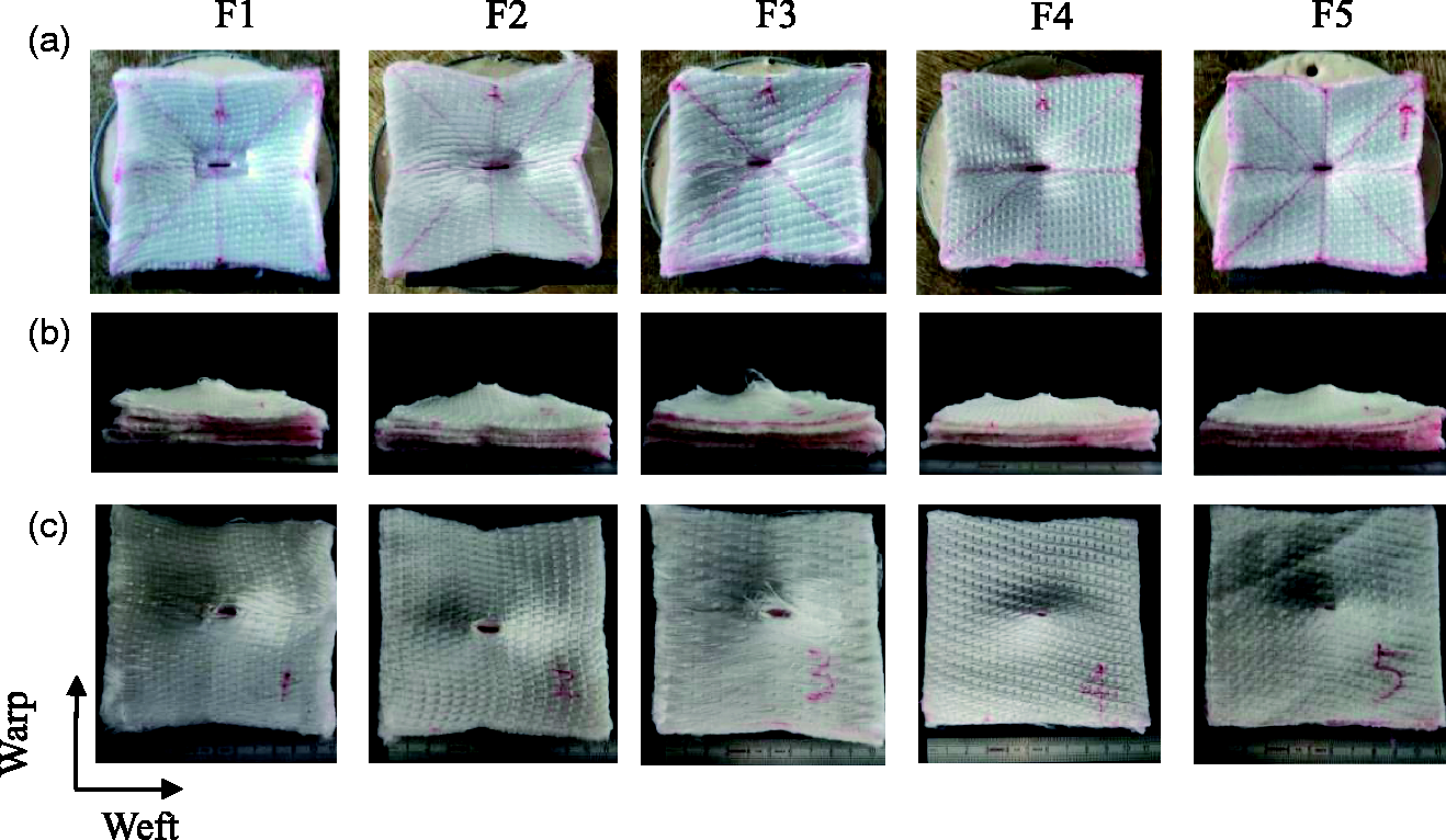
Fabric deformations images of 6 plies of aligned stacked panels [0]6 after stab resistance test, (a) top view of the first impacted ply; (b) front view of the 6 impacted plies of 3DWIFS; (c) top view of the last and sixth impacted ply.
Figure 5 shows the deformation images of the top view of the first impacted ply of 3DWIFs, front view of all the 6 plies of 3DWIFs, and the top view of the last and sixth ply of the impacted ply of 3DWIFs after the stab resistance tests with the angular orientation value of 0°. It is observed fom the top surface of these fabrics that the fabrics were finely cut along the blade, as shown in Figure 5(a). The first tested fabric panel has been subjected to compression through the thickness (Z-direction) at the initial stage of the blade penetration and simultaneously submitted to be cut by the blade cutting edge, referring to the mechanism of the blade penetration through the fiber-reinforced polymer composites [16]. The F1, F2 and F3 fabrics showed a wide damaged area (Figure 5(a)) for the neat target and the blade impactor penetrates the 3DWIFs by cutting the HMWPE fiber with the cutting edge of the blade. Then the broken fibers were pushed by the blade and protruded back to the bottom surface, as shown in Figure 5(b). The F4 and F5 fabrics showed a similar failure mode compared to the other three types of fabrics, but they had a narrower damage area (Figure 5(a)). It can be observed that the fabrics were compressed and bumped and grooves were formed that radiates from the center to the edge (Figure 5(b)). In Figure 5(c), the last impacted plies were cut and penetrated along the blade. All the structures of fabrics show a permanent hole in the center of fabric panels that persisted when the knife blade was removed and some fibers and yarns thoroughly fractured. The yarns at the center were cut and broke, while the surrounding yarns had a clearly bent and some yarns were huddled together and maintain the shape. It can be clearly shown that the F1, F2 and F3 fabrics were perforated with larger rectangular holes, while the F4 and F5 fabrics were perforated with smaller rectangular holes. Especially, some fibers of the weft yarn were pulled out from F1 and F3 fabrics (Figure 5(b)). By comparison, on the one hand, the HMWPE fibers were permanently broken by the cutting in F2 (O-L), F4 (O-T) and F5 (A-T) fabrics. On the other hand, some fibers were pulled out instead of being broken for F1 (A-L) and F3 (A-L) fabrics.
Furthermore, Figure 6 compares the DOP of 6 plies laminates for all architectures after stabbing from different structures in aligned panels [0]6 and [90]6 stabs respectively. The DOP values of the aligned panels [0]6 for all the 3DWIFs structures are higher compared with the aligned panels [90]6 stabs. It indicates that the stab resistance in weft direction is better than the corresponding in warp direction since the weft yarn density is larger than the warp yarn density. In addition, the DOP values are significantly lower for F4 and F5 fabrics, no matter in the stab angle of 0° or 90°, owing to their relatively tight fabric structures like the multi-layers of densely woven fabrics or closely-spaced laminated layers can dissipate the impact energy [39]. The F4 fabric exhibits the lowest DOP value against penetration when compared to the other panels both in warp and weft stabbing directions. Viewed from the results obtained so far, because of the tighter fabric structure, F4 fabric with O-T structure exhibited the most desirable stab resistance performance which is the most effective and suitable for the anti-stabbing.

Comparison of DOP of 6 plies laminates from different fabrics in aligned panels [0]6 and [90]6 respectively submitted to stabbing tests.
Figure 7 shows the silicone prints of aligned panels [0]6 and [90]6 stabs respectively, which illustrates the stab impact-induced fabric deformation from the impact center to the boundaries. The blade is resisted by the strained warp and weft yarns which constitute two directions. In previous studies, three stages of a knife attack have been identified, like indentation, perforation, and further penetration [40,41]. It means that in the initial indentation and perforation step, the fabrics occur with different deformations. In general, compared the surface damaged area between aligned panels [0]6 and [90]6, the value of them are close to each other as shown in Figure 8. The surface damaged area of F4 fabric panels [0]6 and [90]6 are smallest. But, as shown in Figure 7(a), it can be seen that the fabric deformation of all the fabrics in warp yarn direction is smaller than in weft yarn direction and the shape of surface damaged area is close to be rhomboid after aligned panels [0]6 stab. The differences between the F1 and F3 fabrics with A-L structure versus other architectures can also be seen from the deformation prints, where the deformations distribute from the stab impact center along with weft yarns direction compared to the other architectures. As for other structures, the deformations distribute from the stab impact center along with both warp and weft yarns directions. In Figure 7(b), when the aligned fabric panels [90]6 were penetrated, the shape of surface damaged area close to elliptical. But, overall, the deformation of all the fabrics in warp yarn direction is smaller than in weft yarn direction when aligned fabric panels were penetrated by aligned panels [90]6. By comparing with other architectures, although the warp yarn density is lower than weft yarn density, the F4 fabric has the smallest deformation difference between warp and weft yarns directions, which may due to the dense fabric architecture and less yarn slippage before penetration. As a result, the F4 fabric with O-T structure had a better stab resistance and can distribute the stab force evenly with a less damaged area due to the relatively compact fabric structure.
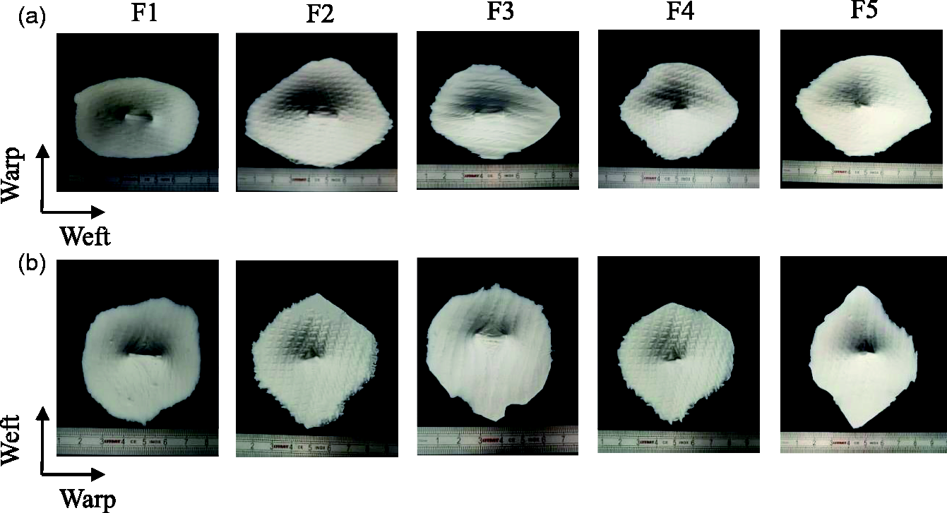
Silicone prints of 6 plies aligned fabric panels after stab tests: (a) aligned panels [0]6 and (b) aligned panels [90]6.

Surface damaged area of 6 plies aligned fabric panels after stab tests of aligned panels [0]6 and [90]6.
Effect of ply orientation on stab resistance
As discussed in the previous section, multiple plies of high-performance fabric are required to get enough protection against high-velocity impact. The stacking of multiple plies fabrics to make a single panel can be done in different ways. According to the research of Javaid et al. [42], the differences between the stab resistance at different penetration angles can be linked to the orientation and availability of yarns under the knife edge. In Figure 9(a), the knife-edge traveling for cutting yarns (T) at different penetration angles is shown with colorful dotted lines. In this study, the 3DWIFs are unbalanced due to the weft density which is about 4 times higher than the warp density. In Figure 9(b) and (c), four layers of weft yarns can be seen from the 3 D structure, which means that the weft densities in each layer are 10 picks/cm the same as the warp yarn density (10 ends/cm). Only the yarns cut by the knife are considered and the width of the blade is assumed as same for each panel at each ply. There are five possibilities concerning the knife travel (T) for each consecutive yarn cutting, as shown in equations:


(a) Illustration of the path, knife-edge travels at different penetrating angles; (b) cross-section weft yarns view of F4 fabric, and (c) 3 D view of F4 fabric.
Therefore, when the penetration angles are 0°, warp yarns resist to knife cutting; when the penetration angles are 90°, weft yarns resist to knife cutting; when the penetration angles are 22.5°, 45°, and 67.5°, both warp and weft yarns offer the resistance simultaneously, although more resistance is offered by a yarn that is cut near to its transverse direction.
Figure 10 shows the DOP of the 6 plies panels in different ply orientations via the stab resistance test with the same impact energy. In the case of the aligned multi-ply fabric panels, the panel construction with ply orientation of [90]6 shows the lower DOP value by comparing with the ply orientation of [0]6, which is same as the result shown in Figure 6. As shown in equations (1) to (7) above, the knife travel distance T[90]6 has the largest value, which means that more yarns are cut under the penetration angle of 90° at the same plies of panel. Although the knife travel distance T[0]6 has the lowest value, the DOP values are not the largest compared with other ply orientations. The main reason is that the warp yarns have larger yarn crimps than weft yarns. It perhaps is helpful to improve the inter yarn friction during stab test. In the case of the angled multi-ply fabric panels, the panel construction with the layering sequence of [0/22.5/45/67.5/0/22.5] generally shows lower DOP values than the layering sequence of [0/22.5/45/67.5/0/0] which has the highest DOP value. It is supported by the above conclusion from Figure 8 that both warp and weft yarns offer stab resistance simultaneously and the layering sequence of [0/22.5/45/67.5/0/22.5] provides more resistance because of the larger knife travel distance T22.5 at the penetration angle of 22.5° for the last ply of fabric panel. Besides, no matter the ply orientation of fabric panels is aligned or angled, the structure of F4 fabric still shows the lowest DOP value, which confirms again the above results that F4 fabric architecture has the best stab resistance. In general, the angled fabric panels have higher DOP value under stab impact, while there is no obvious benefit of angled fabric panels in stab resistance properties for 6 plies panels fabrics. Therefore, the DOP does not decrease when the fabric panel is constructed with angled plies which demonstrate that stab resistance may not only be related to the knife travel distance T of different ply orientation but also be relevant to the yarn crimps difference.
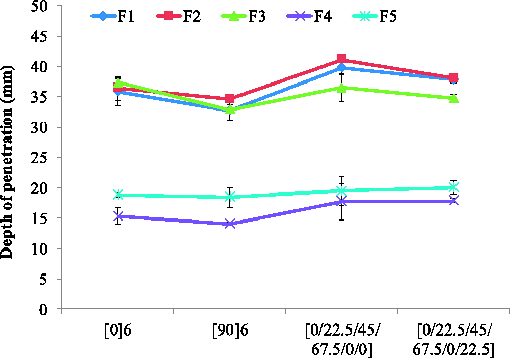
Comparison of DOP of 6 plies panels in different ply orientations from different fabrics.
To further verify the above results, the relatively symmetrical stacking sequences [0/22.5/45/67.5]2 were proposed in eight plies panels of F4 fabric according to the Ref. [36]. In Figure 11, it reveals again that the panel construction with an aligned panel [90]6 ply orientation shows the lowest DOP value. The result indicates again that the DOP does not decrease when the fabric panel is constructed with angled plies. It shows a different conclusion in Wang et al. [36] that the panel [0/22.5/45/67.5]2 shows the best impact performance of the panels compared that plain woven fabrics almost always show an orthotropic material behavior arising from the structural arrangement. The mean reason is that the warp density and weft density of the unbalanced fabric has a big difference in this study. Even though the knife travel distance T[0]8 is lower than T[0/22.5/45/67.5]2, the DOP values are close to each other for these two different ply orientation panels. Thus it is hard to make the conclusion which ply orientation has a better advantage to stab resistance between [0]8 and [0/22.5/45/67.5]2. Aligned panels [90]8 have the best stab resistance among these three different ply orientation panels and there is a small tiny difference of stab resistance between aligned panels [0]8 and angled panels [0/22.5/45/67.5]2 when it has increased to 8 plies panels.
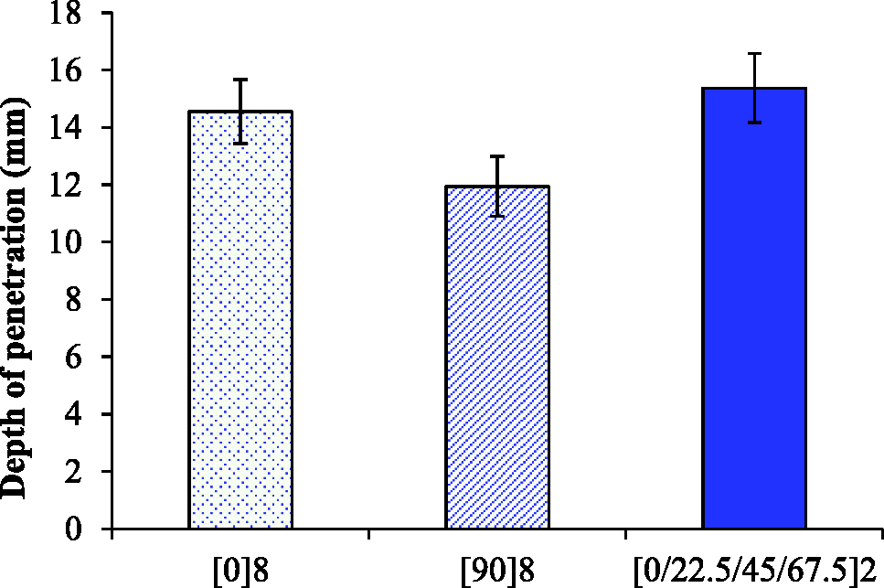
DOP of 8 plies panels in different ply orientations of F4 fabric.
By comparison, the surface damaged areas of 8 plies F4 fabric panels are about the same size, as shown in Figure 12. However, the surface damaged areas of 8 plies F4 fabric panels after stab impact show difference shapes among three stacking sequences, as shown in Figure 13. The stab impactor is resisted by the strained warp and weft yarns, which constitute only two directions in aligned [0]8 and [90]8. The shapes of surface damaged areas are close to be rhomboid. In the [0/22.5/45/67.5]2 targets, additional directions contribute to the stab resistance, which is the same as Gürgen et al. [17] stated that the impact energy is distributed through different straining paths and thereby increasing the energy absorption resistance. From the surface damaged area point of view, it trends to be central symmetrical and is roughly circular of angled fabric panels [0/22.5/45/67.5]2 compared to other panels, as shown in Figure 13(c). This is because as the different fabric layers are oriented along different axes, the assembly approaches isotropy. Post stab impact, the pyramid formed has a quadrilateral base because of the two principal axes along which the diagonals of the base align. Hence, if there are more than two sets of perpendicular axes, as in the case of a multi-layered fabric with angle ply orientation, the base may tend to be circular, so that the pyramid approximately becomes a cone and hence, the energy absorption increases [36].

Damaged area of 8 plies fabric panels of F4 fabric after stab tests of [0]8, [90]8, and [0/22.5/45/67.5]2.

Silicone prints of 8 plies fabric panels of F4 fabric after stab tests: (a) [0]8; (b) [90]8, and (c) [0/22.5/45/67.5]2.
In order to perform a further comparison of different ply orientation of stacking sequences of stab resistance differences among aligned panels [0]16, [90]16 and angled panels [0/22.5/45/67.5]4, 16 plies panels in different ply orientations of F4 fabric were tested. Figure 14 shows the results of the DOP for each panel. According to the results, aligned panels [0]16 differ from aligned panels [90]16 and [0/22.5/45/67.5]4. It shows that aligned panels [90]16 and [0/22.5/45/67.5]4 do not be penetrated when the panels increase into 16 plies. The ply orientation of stacking sequences panel [0/22.5/45/67.5]4 has better stab resistance than panel [0]16 of F4 fabric with O-T structure. Concerning the knife travel (T) for each consecutive yarn cutting, as shown in equations (3) to (6), the knife travel distance T[0]16 is much lower than T[0/22.5/45/67.5]4 that less yarns were cut by the knife blade in the fabric stacking sequences panel. In general, when the number of plies is more, the the main influence factor is the knife travel (T). Besides, the change of ply orientation in fabric stacking sequences panel of T[0/22.5/45/67.5]4 is not conducive for the blade to penetrate into the gaps of the fabric which means that more yarns are effectively cut. Therefore, both the knife travel distance and yarn crimp differences may be the impact factors on the final stab resistance of different ply orientations panels.
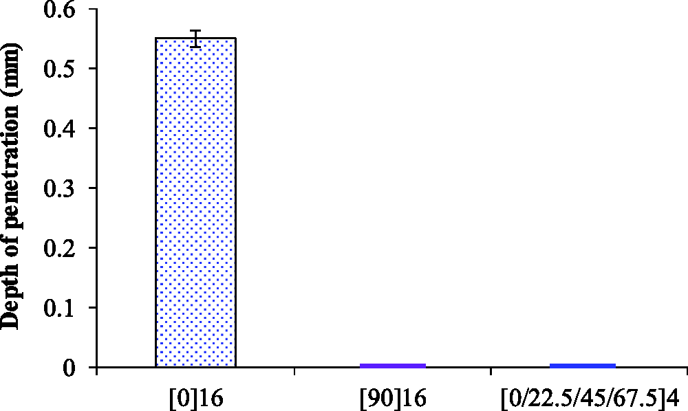
DOP of 16 plies panels in different ply orientations of F4 fabric.
Effect of number of fabric plies
As shown in Figure 15, the relationship between the DOP value and the number of fabric plies from different structures fabrics is found which can be obtained by curve-fitting the measured data. The change of fabric plies is significantly related to the dynamic stab resistance As mentioned above. It can be seen that, the DOP of the impact knife into the backing material tends to linearly decrease with the increase of plies number. It reveals similar results as the study of El Messiry et al. [7] that when the number of plies increases, the impact energy is more absorbed by the cumulative amount of the layers, so that the DOP of the impact knife into the backing material decreases. By contrast, in the case of less number of fabric plies, the DOP values of F1, F2, and F3 fabrics have a similar trend and decline relatively slow with the increase of fabric plies number, while the DOP values of F4 and F5 fabrics have a similar trend and decline relatively rapidly with the increase of fabric plies number. The result indicated that, within a certain number of fabric plies, the stab resistance increases with an increasing number of fabric plies.

DOP of different fabrics stabbed with the 0° angle configuration as related to the number of plies.
Moreover, the relationship between DOP and number of fabric plies is further discussed with the increase of more number of fabric plies. As can be seen in Figure 16, there is an obvious non-linear relation between DOP and the number of layers of F4 fabric structures. As the number of fabric plies increases, the DOP starts to drop suddenly, while the decline gradually becomes less noticeable as the number of layers increases to the zero value of DOP. It indicates that the increase of the number of fabric plies can significantly enhance its stab resistance performance, but when it reaches a certain number of layers, the effect of the number of fabric plies is limited and cannot improve stab resistance performance. Dynamic stab resistance had linear relation to the number of fabric plies with fewer fabric plies, but dynamic stab resistance showed a parabolic relationship generally with the increase of much more fabric plies until it reaches its limits.
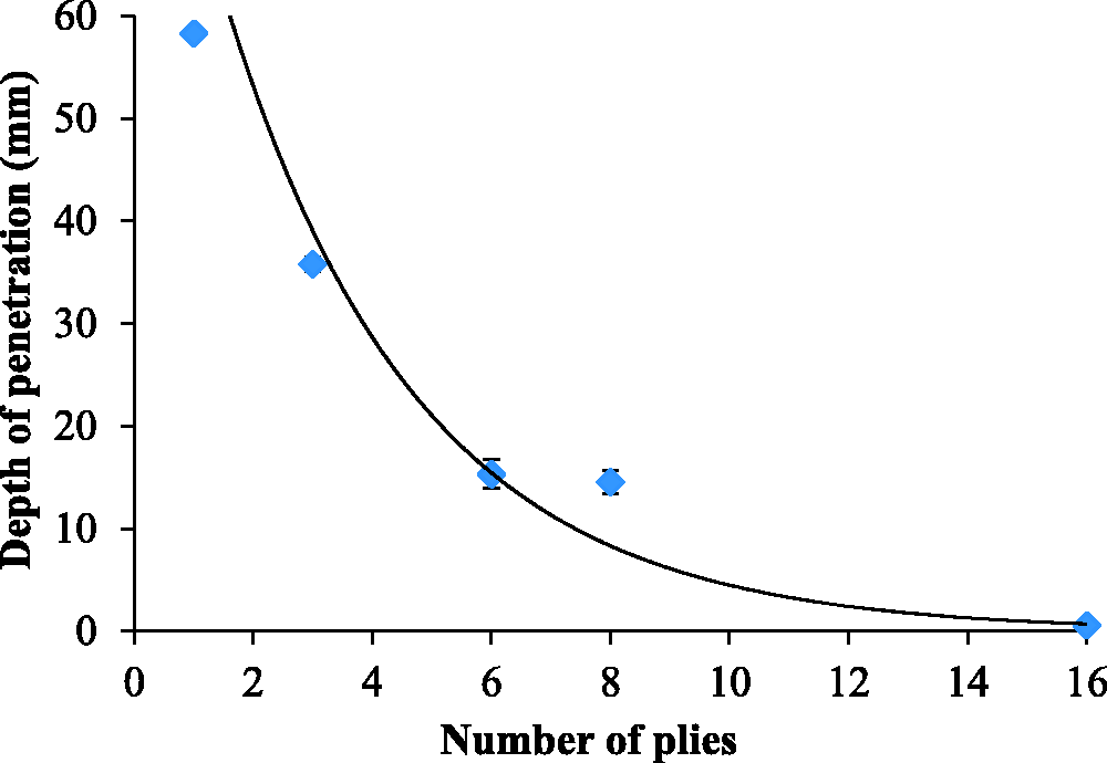
DOP of F4 fabrics stabbed in the angle of 0° as related to the number of plies.
Conclusions
This study successfully prepared a systematic comparison of 3 D warp interlock fabrics for resisting against dynamic stab attacks. Five representative types of 3 D warp interlock fabrics were chosen for this study, including Angle-Through-the-thickness interlock, Angle-Layer-to-layer interlock, Orthogonal-Through-the-thickness interlock, Orthogonal-Layer-to-layer interlock. The stab resistance experiment was performed with HOSDB/P1/B sharpness blades on the HMWPE fabrics, with the same impact energy at the same location, to measure the depth of penetration and print fabric deformation by the silicone print. As a result, multi-ply of 3 D warp interlock woven design affects dynamic stab resistances. It was observed that F4 fabric with Orthogonal-Through-the-thickness interlock structure reveals the most favorable stab resistance compared to other structures and the stab resistance in weft direction is higher than that in the warp direction. It can be highlighted that the main structural parameters of the 3 D warp interlock fabric as the binding warp yarns architecture have revealed the orthogonal-through-the-thickness as the best candidate for stabbing protection. Besides, the orientation of plies significantly affects the stab resistance of the multi-ply fabric panels after stab impact. The distance that cutting knife travelled for cutting consecutive yarns was different from the change in knife penetration angle that, to some extent, affected the stab resistance. It indicated that the angled panels do not always increase the stab resistance of 3 D warp interlock fabric compared with the aligned panel since the warp and weft density are not same. When the number of plies reached a certain limit, the ply orientation is conducive to improving the stab resistance performance of the fabric panel. It can be concluded that the increase in fabric plies has effects on decreasing the trauma and perforation values. To satisfy protection level 1 of the HOSDB standard (penetration depth < 7 mm), the 3DWIF should be with much more plies of the fabric panel. But there are limited benefits to improve stab resistance performance after over a certain number of fabric plies.
Footnotes
Declaration of conflicting interests
The author(s) declared no potential conflicts of interest with respect to the research, authorship, and/or publication of this article.
Funding
The author(s) disclosed receipt of the following financial support for the research, authorship, and/or publication of this article: The authors would like to acknowledge the China Scholarship Council (Project no. 201708420167) for supporting this research.